EP0230403B1 - Hebevorrichtung für die Mastteile eines zusammengebauten Mastes, insbesondere eines beweglichen Antennenmastes der Fachwerkart - Google Patents
Hebevorrichtung für die Mastteile eines zusammengebauten Mastes, insbesondere eines beweglichen Antennenmastes der Fachwerkart Download PDFInfo
- Publication number
- EP0230403B1 EP0230403B1 EP19870850011 EP87850011A EP0230403B1 EP 0230403 B1 EP0230403 B1 EP 0230403B1 EP 19870850011 EP19870850011 EP 19870850011 EP 87850011 A EP87850011 A EP 87850011A EP 0230403 B1 EP0230403 B1 EP 0230403B1
- Authority
- EP
- European Patent Office
- Prior art keywords
- mast
- jacket
- sections
- transport screw
- screw
- Prior art date
- Legal status (The legal status is an assumption and is not a legal conclusion. Google has not performed a legal analysis and makes no representation as to the accuracy of the status listed.)
- Expired
Links
- 230000003028 elevating effect Effects 0.000 title claims description 9
- 230000007246 mechanism Effects 0.000 claims description 11
- 230000002093 peripheral effect Effects 0.000 claims description 4
- 238000010168 coupling process Methods 0.000 description 4
- 238000005859 coupling reaction Methods 0.000 description 4
- 230000008878 coupling Effects 0.000 description 2
- 229910000906 Bronze Inorganic materials 0.000 description 1
- 239000010974 bronze Substances 0.000 description 1
- 230000008094 contradictory effect Effects 0.000 description 1
- KUNSUQLRTQLHQQ-UHFFFAOYSA-N copper tin Chemical compound [Cu].[Sn] KUNSUQLRTQLHQQ-UHFFFAOYSA-N 0.000 description 1
- 238000003780 insertion Methods 0.000 description 1
- 230000037431 insertion Effects 0.000 description 1
- 239000000463 material Substances 0.000 description 1
- 230000000087 stabilizing effect Effects 0.000 description 1
Images

Classifications
-
- E—FIXED CONSTRUCTIONS
- E04—BUILDING
- E04H—BUILDINGS OR LIKE STRUCTURES FOR PARTICULAR PURPOSES; SWIMMING OR SPLASH BATHS OR POOLS; MASTS; FENCING; TENTS OR CANOPIES, IN GENERAL
- E04H12/00—Towers; Masts or poles; Chimney stacks; Water-towers; Methods of erecting such structures
- E04H12/34—Arrangements for erecting or lowering towers, masts, poles, chimney stacks, or the like
Definitions
- the present invention refers to and elevating device for lifting the mast by the lowermost mast sections a sectional mast, especially a movable aerial mast of framework type, comprising a foot portion with a mast support and guide jacket, said elevating device including a power-operated screw mechanism, the elongated transport screw of which extends vertically along one side of the guide jocket.
- Such a mast and lifting device is known from BE-A 449 601.
- Movable aerial masts have to fill a plurality of partly contradictory requirements. Thus, they have to be strong and rigid but still relatively light and easily mountable and dismountable.
- Conventional mast structures usually are of framework type and the masts are put together from a number of sections. The mast is erected by arranging at a desired place a foot portion of the mast having a support and guide jacket therefor and introducing into said jacket the sections one by one, coupling them together with the nearest preceding section and raising them by means of any suitable raising and lowering mechanism a sufficient distance for allowing the introduction of the subsequent mast section into the jacket.
- the conventional raising and lowering mechanisms have been rope blocks or chain winches having a hook which is connected with the lower end of each mast section after the same has been inserted into the guide jacket after which raising is made, the mast is locked, the hook released and the raising and lowering mechanism returned to the initial position for again connecting the hook to the lower end of the subsequent mast section.
- the object of the present invention now is to suggest such a device and the invention comprises mast and device of the aforementioned type which is characterized in that the screw contacts externally with its periphery the peripheral contour of a mast section housed parallel therewith within the jacket and in that each mast section in its lower portion at the point of contact on the peripheral contour is provided with a mechanical component serving as an open-sided nut segment meshing with the threads of the transport screw.
- the transport screw certainly operates intermittently but permanently in the same direction during the erection of the mast and in the opposite direction during the lowering of said mast.
- the respective mast sections only need to be inserted into the support and guide jacket of the foot portion in order to be brought directly into meshing with the transport screw with its nut segment, after which the screw is rotated and the mast section together with the preceding sections is raised a distance substantially corresponding to the length of one section, after which the subsequent mast section is introduced into the guide jacket, coupled to the preceding mast section and thereafter raised by means of the transport screw in cooperation with the nut segment of the last-mentioned section.
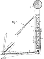
- Fig 1 is a side elevational view of a mast with an elevating device according to the invention with a support and guide jacket in a foot portion of the mast and Fig 2 is a plan view from above of said guide jacket.
- a movable aerial mast of framework type comprises a foot portion 1 and a plurality of mutually equal mast sections 2 of framework type and in the present case having triangular cross section.
- the uppermost section carries in its upper end an aerial element such as a pa- raboloidal aerial 3.
- the sections 2 are provided with suitable mountings for some suitable kind of coupling means such as a bolt connection of easy-coupling type.
- the mast In its erected position the mast rests with its lowermost sections in a support and guide jacket 4 having an elevating device 5.
- the jacket has the same general cross sectional shape as the mast sections 2, in the present case thus triangular shape, and surrounds the lowermost mast sections 2 with moderate clearance.
- the height of the jacket substantially corresponds to the total length of two mast sections 2 and for stabilizing the mast the jacket 4 is provided with support legs 6 and side struts 7 protruding from the corners of the triangular cross section. From the top as well as from other levels of height of the mast, if desired, usually also extend span wires 8.
- the jacket which suitably also is of framework type, is provided in the lower portion of one of its sides with an opening 10 in said side wall.
- the mast sections 2 are guided by means of suitable guide members 11, preferably in the form of guide rollers cooperating with the corner edges of said mast sections 2.
- the elevating or raising and lowering mechanism 5 may comprise an elongated vertical transport screw 12 which is along another side of the guide jacket 4 also provided with a suitable opening.
- the screw 12 has a length which at least corresponds to the length of each mast section 2 and extends from a bottom of the guide jacket 4 and upwardly to a position above the level of a mast section 2 standing on the bottom of the jacket 4 or, in other words above the open portion of the framework at the insertion and removal side of the jacket 4.
- the transport screw 12 is connected with some suitable kind of drive mechanism 13 not further illustrated, such as a worm drive driven by an electric motor for 12 or 24 volts.
- the device also is provided with a connection for mounting of a hand crank for allowing manual operation of the transport screw in case of lack of electric current.
- the transport screw 12 may be arranged in a plane coinciding with the center line of the adjacent jacket side such that the screw with its periphery approximately contacts externally one of the sides of a mast section 2 located in the jacket 4 and oriented parallelly thereto along an axis extending in said side, said axis preferably being the longitudinal center line of said side.
- each mast section 2 according to the invention may be provided at the lower end of said center line with a nut segment 14 adapted for meshing with the threads of said transport screw 12.
- the nut segment may be constituted by a slide block of suitable material such as bronze or by a roller.
- the mast provided with the elevating device according to the invention may be erected in the following way. Firstly, the support and guide jacket 4 is arranged and levelled at the desired place and thereafter a first mast section 2 is inserted into the guide jacket 4 through the opening in one of the sides thereof, said section 2 of course being oriented in such a way that a side provided with a nut segment 14 is turned towards the side of the jacket 4 at which transport screw 12 is located. After that the rotation of the transport screw 12 is started and owing to the movement of the nut segment 14 along the threads of the screw 12 a raising of the mast section 2 through the jacket 4 is obtained.
Landscapes
- Engineering & Computer Science (AREA)
- Architecture (AREA)
- Civil Engineering (AREA)
- Structural Engineering (AREA)
- Forklifts And Lifting Vehicles (AREA)
Claims (2)
Applications Claiming Priority (2)
| Application Number | Priority Date | Filing Date | Title |
|---|---|---|---|
| SE8600213A SE451376B (sv) | 1986-01-17 | 1986-01-17 | Hoj- och senkanordning for mastsektioner vid en sektionsvis sammansettbar mast, serskilt en flyttbar antennmast av fackverkstyp |
| SE8600213 | 1986-01-17 |
Publications (2)
| Publication Number | Publication Date |
|---|---|
| EP0230403A1 EP0230403A1 (de) | 1987-07-29 |
| EP0230403B1 true EP0230403B1 (de) | 1989-08-09 |
Family
ID=20363133
Family Applications (1)
| Application Number | Title | Priority Date | Filing Date |
|---|---|---|---|
| EP19870850011 Expired EP0230403B1 (de) | 1986-01-17 | 1987-01-16 | Hebevorrichtung für die Mastteile eines zusammengebauten Mastes, insbesondere eines beweglichen Antennenmastes der Fachwerkart |
Country Status (3)
| Country | Link |
|---|---|
| EP (1) | EP0230403B1 (de) |
| DE (1) | DE3760412D1 (de) |
| SE (1) | SE451376B (de) |
Family Cites Families (10)
| Publication number | Priority date | Publication date | Assignee | Title |
|---|---|---|---|---|
| DE1066720B (de) * | 1959-10-08 | |||
| BE449601A (de) * | ||||
| DE119095C (de) * | ||||
| FR1256677A (fr) * | 1960-02-12 | 1961-03-24 | Dispositif pour le montage de grues à mât formé d'éléments superposés | |
| DE1228040B (de) * | 1961-09-19 | 1966-11-03 | Markus Schmidt Tychsen Derrick | Kran, dessen Saeule aus einer Mehrzahl von Mastelementen aufgebaut ist |
| FR1325120A (fr) * | 1962-03-23 | 1963-04-26 | Installation de mât de support extensible | |
| AT292966B (de) * | 1966-10-12 | 1971-09-27 | Friedrich Freimueller | Aus Schüssen aufgebauter Gittermast |
| FR1543012A (fr) * | 1967-10-24 | 1968-10-18 | Dispositif de transformation d'un mouvement rotatif en une translation rectiligne, particulièrement pour le déplacement d'une charge | |
| FR1585396A (de) * | 1968-11-26 | 1970-01-16 | ||
| FR2247913A6 (en) * | 1971-07-22 | 1975-05-09 | Comabi | Elevator formed of scaffolding frames - has ladder elements enclosing vert. operating screws |
-
1986
- 1986-01-17 SE SE8600213A patent/SE451376B/sv not_active IP Right Cessation
-
1987
- 1987-01-16 EP EP19870850011 patent/EP0230403B1/de not_active Expired
- 1987-01-16 DE DE8787850011T patent/DE3760412D1/de not_active Expired
Also Published As
| Publication number | Publication date |
|---|---|
| DE3760412D1 (en) | 1989-09-14 |
| SE451376B (sv) | 1987-10-05 |
| SE8600213D0 (sv) | 1986-01-17 |
| SE8600213L (sv) | 1987-07-18 |
| EP0230403A1 (de) | 1987-07-29 |
Similar Documents
| Publication | Publication Date | Title |
|---|---|---|
| US3751863A (en) | Extensible structural members | |
| US4497591A (en) | Advancing mechanism and system utilizing same for raising and lowering a work platform | |
| US3679174A (en) | Jack or lift mechanism and drive therefor | |
| KR20180035717A (ko) | 무거운 하중을 들어올리기 위한 장치 | |
| US4655640A (en) | Advancing mechanism and system utilizing same for raising and lowering a work platform | |
| EP0230403B1 (de) | Hebevorrichtung für die Mastteile eines zusammengebauten Mastes, insbesondere eines beweglichen Antennenmastes der Fachwerkart | |
| US4125193A (en) | Climbing device for climbing crane | |
| CN109650226A (zh) | 一种液压顶升钢平台防坠落支撑梁柱系统及其使用方法 | |
| EP0026543B1 (de) | Ohne Hilfsmittel montierbare Teleskopstruktur | |
| US5131628A (en) | Mechanical jack | |
| CN112814474A (zh) | 一种警示围栏装置 | |
| CN107246138A (zh) | 一种可循环送料的建筑施工升降平台 | |
| US3493129A (en) | Vehicle garage | |
| KR960002897Y1 (ko) | 차량 정비용 리프트 장치 | |
| CN115259029B (zh) | 一种新型建筑施工现场升降装置 | |
| KR102761807B1 (ko) | 타워크레인의 마스트 조립 및 해체 장치 | |
| RU2793508C2 (ru) | Подъемный механизм для рельсовой подъемной системы | |
| SU853058A1 (ru) | Силова скольз ща стойка,пРЕиМущЕСТВЕННО дл СКОльз щиХОпАлубОК | |
| KR100197299B1 (ko) | 주차장치 | |
| EP1153878A2 (de) | Bedieneinrichtung für eine Hebebühne | |
| GB2323073A (en) | A collapsible tower | |
| RU2066673C1 (ru) | Передвижной подъемник | |
| CN2142528Y (zh) | 升降式高杆灯具 | |
| KR950007711Y1 (ko) | 에스컬레이터의 지지구 | |
| DE10157795B4 (de) | Überladebrücke mit Absturzsicherung |
Legal Events
| Date | Code | Title | Description |
|---|---|---|---|
| PUAI | Public reference made under article 153(3) epc to a published international application that has entered the european phase |
Free format text: ORIGINAL CODE: 0009012 |
|
| AK | Designated contracting states |
Kind code of ref document: A1 Designated state(s): CH DE FR GB IT LI |
|
| 17P | Request for examination filed |
Effective date: 19871212 |
|
| 17Q | First examination report despatched |
Effective date: 19881111 |
|
| GRAA | (expected) grant |
Free format text: ORIGINAL CODE: 0009210 |
|
| AK | Designated contracting states |
Kind code of ref document: B1 Designated state(s): CH DE FR GB IT LI |
|
| ITF | It: translation for a ep patent filed | ||
| ET | Fr: translation filed | ||
| REF | Corresponds to: |
Ref document number: 3760412 Country of ref document: DE Date of ref document: 19890914 |
|
| PLBE | No opposition filed within time limit |
Free format text: ORIGINAL CODE: 0009261 |
|
| STAA | Information on the status of an ep patent application or granted ep patent |
Free format text: STATUS: NO OPPOSITION FILED WITHIN TIME LIMIT |
|
| 26N | No opposition filed | ||
| PGFP | Annual fee paid to national office [announced via postgrant information from national office to epo] |
Ref country code: GB Payment date: 19920114 Year of fee payment: 6 Ref country code: FR Payment date: 19920114 Year of fee payment: 6 |
|
| PGFP | Annual fee paid to national office [announced via postgrant information from national office to epo] |
Ref country code: DE Payment date: 19920127 Year of fee payment: 6 |
|
| PGFP | Annual fee paid to national office [announced via postgrant information from national office to epo] |
Ref country code: CH Payment date: 19920128 Year of fee payment: 6 |
|
| ITTA | It: last paid annual fee | ||
| PG25 | Lapsed in a contracting state [announced via postgrant information from national office to epo] |
Ref country code: GB Effective date: 19930116 |
|
| PG25 | Lapsed in a contracting state [announced via postgrant information from national office to epo] |
Ref country code: LI Effective date: 19930131 Ref country code: CH Effective date: 19930131 |
|
| GBPC | Gb: european patent ceased through non-payment of renewal fee |
Effective date: 19930116 |
|
| PG25 | Lapsed in a contracting state [announced via postgrant information from national office to epo] |
Ref country code: FR Effective date: 19930930 |
|
| REG | Reference to a national code |
Ref country code: CH Ref legal event code: PL |
|
| PG25 | Lapsed in a contracting state [announced via postgrant information from national office to epo] |
Ref country code: DE Effective date: 19931001 |
|
| REG | Reference to a national code |
Ref country code: FR Ref legal event code: ST |
|
| PG25 | Lapsed in a contracting state [announced via postgrant information from national office to epo] |
Ref country code: IT Free format text: LAPSE BECAUSE OF NON-PAYMENT OF DUE FEES;WARNING: LAPSES OF ITALIAN PATENTS WITH EFFECTIVE DATE BEFORE 2007 MAY HAVE OCCURRED AT ANY TIME BEFORE 2007. THE CORRECT EFFECTIVE DATE MAY BE DIFFERENT FROM THE ONE RECORDED. Effective date: 20050116 |