EP0230341B1 - Buse de pulvérisation électrostatique - Google Patents
Buse de pulvérisation électrostatique Download PDFInfo
- Publication number
- EP0230341B1 EP0230341B1 EP87300008A EP87300008A EP0230341B1 EP 0230341 B1 EP0230341 B1 EP 0230341B1 EP 87300008 A EP87300008 A EP 87300008A EP 87300008 A EP87300008 A EP 87300008A EP 0230341 B1 EP0230341 B1 EP 0230341B1
- Authority
- EP
- European Patent Office
- Prior art keywords
- nozzle
- air
- stream
- passageway
- electrostatic
- Prior art date
- Legal status (The legal status is an assumption and is not a legal conclusion. Google has not performed a legal analysis and makes no representation as to the accuracy of the status listed.)
- Expired
Links
Images
Classifications
-
- B—PERFORMING OPERATIONS; TRANSPORTING
- B05—SPRAYING OR ATOMISING IN GENERAL; APPLYING FLUENT MATERIALS TO SURFACES, IN GENERAL
- B05B—SPRAYING APPARATUS; ATOMISING APPARATUS; NOZZLES
- B05B5/00—Electrostatic spraying apparatus; Spraying apparatus with means for charging the spray electrically; Apparatus for spraying liquids or other fluent materials by other electric means
- B05B5/025—Discharge apparatus, e.g. electrostatic spray guns
- B05B5/043—Discharge apparatus, e.g. electrostatic spray guns using induction-charging
Definitions
- the invention relates to an electrostatic nozzle assembly.
- electrostatic spray coating a stream of coating material is atomized into finely divided particles which are electrostatically charged. The charged particles are then directed at a surface to be coated which is held at a different electrical potential to that of the particles. Due to the electrostatic attraction and the proximity of the charged particles to the surface to be coated electrostatic forces move the particles onto the surface where they are deposited to form a coating or layer.
- electrostatic coating devices employ high voltages, e.g., 50 kilovolts or more, to create a corona discharge through which the particles pass to become electrostatically charged.
- high voltages e.g., 50 kilovolts or more
- waterborne pesticides are highly conductive and the charge applied thereto is transferred back through the pesticide stream to its holding tank.
- the tank must therefore be electrically isolated from earth. When isolated, the tank becomes charged with the same high voltage as the electrical field, and must be electrically insulated and isolated from persons spraying the pesticide to avoid serious electrical hazards.
- Special insulation and mounting of the holding tank of a pesticide sprayer adds substantially to its costs, and therefore the use of corona electrostatic charging of waterborne pesticides has been traditionally cost prohibitive and dangerous.
- Electrostatic spraying device for agricultural applications which employs low voltage inductively to charge a stream of waterborne pesticides or similar treatment chemicals is shown, for example, in Patent Specification US-A 4 004 733 to Law.
- Electrostatic spray nozzles of this general kind comprise a nozzle body formed with a fluid passageway in which a stream of waterborne pesticide is atomized into finely divided droplets or particles.
- An electrode is mounted in the nozzle body, in axial alignment with the fluid passageway, and is operable electrostatically to charge the particles forming the atomized stream before they exit the nozzle body.
- the electrostatic charge is applied to the fluid stream at the point of atomization by induction using a voltage on about 2 kilovolts, as opposed to ionized field systems which typically employ voltages of 50 kilovolts to 100 kilovolts or higher.
- the charged particles which are entrained in the stream of air are then expelled through the fluid passageways the nozzle body, which propels the charged particles onto the trees, grapevines or row crops to be coated.
- Patent Specification FR-A 2 317 016 discloses an electrostatic spray nozzle including a body with a central passageway through which a liquid is passed and a plurality of passageways surrounding the central liquid passageway and through which air is passed to break up the liquid emerging from the central passageway into a stream of droplets.
- the stream of droplets is directed into and through the aperture of an annular inductor ring which is charged with high voltage, thereby to apply an electrostatic charge to the droplets of the stream of droplets discharged from the body.
- an electrostatic nozzle assembly for coating objects comprising:
- Such a nozzle assembly can provide a wide spray pattern of electrostatically charged particles for deposition of pesticides onto trees or other crops to be coated, and can avoid earthing of the electrode which imparts the electrostatic charge to the pesticide to maintain high charging efficiency.
- the swirling, substantially spiral motion of the air stream, and the charged particles entrained therein, can produce a wide spray pattern since the electrostatically charged particles tend to continue to rotate after they exit the discharge orifice and thus quickly fan radially outwardly in a wide pattern toward the objects to be coated.
- the outer surface of the nozzle assembly near the discharge orifice is formed with an irregular shape to lengthen the electrical path between electrostatically charged particles ejected from the discharge orifice, and the position at which the nozzle body of the spray device is connected to earth.
- the nozzle assembly can be a multiple component assembly wherein the components are releasably secured together and can be easily disassembled for maintenance and repair, or replacement of key components.
- a stream of waterborne pesticide held at or near earth potential, can be directed into the aperture of the inductor ring where it is atomized into finely divided particles by a swirling, substantially spirally moving stream of air.
- a flow path of the stream of waterborne pesticide to the inductor ring, and atomization of the stream thereat, is provided by a swirl plate which is disposed between the inductor ring and nozzle body.
- the swirl plate is formed with a tapered central bore communicating with the liquid passageway formed in the nozzle body.
- the tapered central bore terminates at a nozzle tip having an outlet disposed approximately midway into the aperture of the inductor ring. Waterborne pesticide can thus be directed from the liquid passageway, to the tapered central bore and through the outlet in the nozzle tip into the aperture of the inductor ring.
- the swirl plate is also formed with a plurality of atomizing air channels which communicate with the air passageway and atomize the stream of waterborne pesticide discharged into the aperture of the inductor ring by the nozzle tip.
- the channels each extend radially outwardly from the nozzle tip of the central bore, substantially tangentially thereto, and terminate at an annular groove formed in the swirl plate which communicates with the air passageway.
- the channels preferably are tapered and decrease in cross section from the annular groove to the nozzle tip. Air introduced into the annular groove through the air passageway is directed by the channels along flow paths which are substantially tangential to the nozzle tip of the central bore and the stream of waterborne pesticide discharged therefrom.
- a swirling, spirally moving air stream is therefore created by the channels at the outlet of the nozzle tip which is accelerated by the tapered channels towards the nozzle tip and contacts the stream of waterborne pesticide at its highest velocity thereat to form finely divided droplets or particles.
- the nozzle tip of the central bore is disposed within the aperture of the inductor ring so that the waterborne pesticide stream is atomized by the swirling air stream in the presence of the electrostatic field created by the inductor ring.
- An induced electrostatic charge is imparted to each particle by the inductor ring for deposition upon the article to be coated.
- the electrostatically charged particles become entrained within the swirling, spirally moving air stream which imparts that same motion to the charged particles. Once expelled from the discharge orifice of the air nozzle, the charged particles tend to continue to move with the same swirling, spiral motion and therefore fan radially outwardly from the discharge orifice to form a wide angle spray pattern for deposition onto trees, vines or row crops to be coated. It is contemplated that in some applications, fewer electrostatic nozzle assemblies according to the invention would be needed to achieve the same coverage of pesticide on the target trees or crops, as compared to prior art spray nozzles.
- the air stream produced by the swirl plate can create an air barrier between the inductor ring and the waterborne pesticide. If the inductor ring became wetted with a film of the waterborne pesticide, a conductive path from the inductor ring to earth via the pesticide stream could be created which would cause the inductor ring to become earthed and ineffective in charging the atomized particle stream.
- the air barrier created by the swirling stream of air from the swirl plate is therefore important in maintaining the inductor ring and adjacent housing dry.
- An electrical standoff can be provided between the discharge orifice of the air nozzle and an earthed bracket which mounts the nozzle body by providing the air nozzle with an annular wall which extends outwardly from the discharge orifice forming a cavity into which the charged particle stream is discharged.
- the exterior of the annular wall includes grooves which form an irregular-shaped outer surface having a plurality of ridges and recesses.
- the wall of the air nozzle is also formed with an inner surface having a taper which increases in cross section as it extends outwardly from the discharge orifice. It has been found that such a tapered surface tends to collect charged particles emitted from the discharge orifice and causes them to drip off the air nozzle before the charged particles can migrate to the outer surface of the air nozzle wall. It is believed that this occurs because of the shape of the electric field lines produced by the charged particles emitted from the discharge orifice.
- an electrostatic nozzle assembly for coating objects comprising:
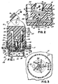
- an electrostatic nozzle assembly 10 includes a nozzle body 12 having a yoke 14 at its upper end which receives a mounting bracket 16 connected thereto by a pin 18.
- the bracket 16 is earthed as indicated at 20.
- the nozzle body 12 can be pivoted with respect to the bracket 16 due to the pin 18 and yoke 14 connection.
- the nozzle body 12 is formed of dielectric material and includes an air passageway 22, a liquid passageway 24 and an electrical passageway 26 all of which extend longitudinally, that is to say in the direction from the base 13 of nozzle body 12 towards the yoke 14.
- Suitable hoses (not shown) connect sources of air, and liquid in the form of waterborne pesticide, to the air and liquid passageways 22, 24, respectively.
- An electrical cable 25 from a source of relatively low voltage 27 is connected to the nozzle body 12 at the electrical passageway 26.
- an air nozzle 28 mounted at the base 13 of the nozzle body 12 is an air nozzle 28 formed of dielectric material.
- the air nozzle 28 is secured in place by a nozzle nut 30, also formed of dielectric material, having a radial flange 31 and internal threads which engage external threads formed on the outer surface 15 of the nozzle body 12.
- the air nozzle 28 is formed with a conical-shaped discharge orifice 32 which terminates within a cavity 34 defined by an annular wall 36.
- the annular wall 36 has an inner surface 38 formed in a generally frusto-conical shape which increases in cross section from the discharge orifice 32 outwardly relative to the axis of the discharge orifice 32.
- the exterior of the annular wall 36 is formed with grooves 40 forming an outer surface 42 of irregular shape having a plurality of recesses and ridges.
- An electrode in the form of an inductor ring 48 having a central aperture 50 rests atop the air nozzle 28 so that the aperture 50 is axially aligned with the discharge orifice 32 in the air nozzle 28.
- the inductor ring 48 is preferably formed of an electrically conductive material which does not corrode in the presence of liquid pesticide or similar chemicals.
- a relatively low voltage, preferably of about 1,000 volts, is applied to the inductor ring 48 to create an electrostatic field across its aperture 50.
- the inductor plate 48 Electrical potential is applied to the inductor plate 48 through the electrical passageway 26 which contains a pin 52 disposed at the base of the electrical passageway 26 and having a tip 54 mounted to the inductor plate 48.
- the upper end of the pin 52 is formed with contact 58 which engages a spring-biased plunger 60 within the passageway 26 and commercially available from Jurgens, Inc. of Cleveland, Ohio under Part No. 27 226.
- the plunger 60 is disposed between the pin 52 and a slug 62 mounted within the uppermost portion of the electrical passageway 26.
- the slug 62 is a section of electrically conductive material which is connected directly to the electrical cable 25 from the source 27 of electrical potential.
- the slug 62, the plunger 60 and the pin 52 together provide an electrical path from the source 27 to the inductor plate 48.
- the spring-biased plunger 60 maintains the elements in electrical contact with one another to ensure that the inductor plate 48 is constantly charged.
- the electrostatic nozzle assembly 10 is operable to atomize a stream of waterborne pesticide into finely divided particles, electrostatically charge the particles and propel the charged particles onto plants or crops to be coated through the discharge orifice 32 of the air nozzle 28.
- the liquid stream is directed to the inductor ring 48, charged, atomized and then carried away by a stream of swirling air formed by a swirl plate 64.
- the swirl plate 64 is made of dielectric material and is positioned directly atop the inductor plate 48 and is separated from the base 13 of the nozzle body 12 by a gasket 66 formed of a flexible, dielectric material. Both the swirl plate 64 and the gasket 66 are formed with a throughbore to receive the pin 52 connected to the inductor plate 48.
- a central bore 68 is formed in the swirl plate 64 in axial alignment with the liquid passageway 24 which tapers radially inwardly from a top surface 70 of the swirl plate 64 to a bottom surface 72 thereof.
- the central bore 68 terminates at a nozzle tip 74 having an outlet 75 which extends outwardly from the bottom surface 72 of the swirl plate 64 and approximately midway into the depth of the aperture 50 of the inductor plate 48 beneath.
- Waterborne pesticide introduced into the liquid passageway 24 flows through a strainer 76 having a check valve (not shown), into the central bore 68 of the swirl plate 64 and then through the outlet 75 in the nozzle tip 74 into the aperture 50 of the inductor plate 48.
- the strainer 76 is commercially available from Spraying Systems Company of Wheaton, Illinois under Part No. 4193A.
- an orifice plate 78 having a metering orifice 80 is positioned between the strainer 76 and the nozzle tip 74 atop an annular shoulder 82 formed in the central bore 68.
- the orifice plate 78 functions to meter the flow of waterborne pesticide from the liquid passageway 24, and directs a stream of waterborne pesticide toward the nozzle tip 74.
- a turbulence pin 84 is mounted to the walls of the swirl plate 64 within the central bore 68, substantially transverse to the orifice 80 in the orifice plate 78, to deflect the waterborne pesticide stream emitted through the orifice 80.
- the pin 84 helps reduce the velocity of the stream and induces turbulence in the stream so that it can be properly atomized and electrostatically charged as described in detail below.
- the orifice plate 78 is commercially available from Spraying Systems Company under Part No. 4916-16.
- the atomization takes place within the aperture 50 of the inductor plate 48 where the stream is discharged from the outlet 75 of the nozzle tip 74.
- atomization of the waterborne pesticide stream is achieved by a plurality of channels 86 formed in the swirl plate 64.
- the channels 86 extend along the bottom surface 72 of the swirl plate 64 and taper downwardly from an annular groove 88 formed in the upper portion 70 of the swirl plate 64 to the central bore 68.
- the annular groove 88 communicates with the air passageway 22.
- Each tapered channel 86 decreases in cross section from the annular groove 88 to the central bore 68.
- the channels 86 have longitudinal axes which are substantially tangential to the central bore 68 and the outlet 75 of the nozzle tip 74.
- Each of the channels 86 therefore defines a flow path for the air supplied by the air passageway 22 which is substantially tangential to the outlet 75 of the nozzle tip 74.
- the channels 86 thus produce a swirling, essentially spiral-shaped flow of air which is accelerated from the annular groove 88 toward the nozzle tip 74, due to the tapered shape of the channels 86. This accelerating flow of air reaches the point of maximum geometric constriction, and therefore maximum velocity in the space between the nozzle tip 74 and the wall of the aperture 50 of inductor ring 48.
- Charging of the waterborne pesticide stream occurs within the aperture 50 of the inductor ring 48. It is believed that the leading end of the waterborne pesticide stream ejected from the nozzle tip 74 is subjected to the electrostatic field created by the inductor ring 48 which has a sufficiently intense negative charge to drive the electrons in the stream back through the stream to earth. This process is enabled by the fact that the pesticide stream is conductive and is itself earthed through the pesticide column leading back to the earthed supply tank (not shown). With the free electrons driven back towards earth and away from the terminal end of the pesticide stream in the nozzle tip 74, the leading end of the stream has an overall positive charge.
- the leading end of the waterborne pesticide stream is then atomized by the swirling air stream from the channels 86 forming finely divided particles having a positive charge, or, of a polarity opposite to that of the inductor ring 48.
- the charged particles are then discharged through the discharge orifice 32 of the air nozzle 28 for deposition upon row crop or other plants to be coated with pesticide. Because the charged particle stream of pesticide is entrained within a swirling stream of air, it tends to continue the spiral or swirling motion after discharge from the discharge orifice 32. This swirling motion causes the particle stream quickly to fan radially outwardly from the discharge orifice 32 to form a wide spray pattern 90 which ensures coverage of the plants to be coated.
- the air stream produced by the channels 86 of the swirl plate 64 forms a high velocity air barrier between the inductor plate 48 and the stream of waterborne pesticide. This is important, because the inductor ring 48 must be maintained at its full electrical potential efficiently to impart an electrostatic charge to the particles. If the stream of waterborne pesticide, which is held at earth potential, was permitted to wet the surface of the inductor ring 48, a conductive path from the inductor ring 48 to earth through the pesticide stream and earthed supply tank could be created which would earth the inductor ring 48 and render it ineffective in charging the atomized particle stream.
- the barrier of air created by the channels 86 of the swirl plate 64 effectively prevents the waterborne pesticide from wetting the surface of the inductor plate 48 and therefore greatly enhances its charging efficiency.
- the charged particles emitted from the discharge orifice 32 of the air nozzle 28 are propelled toward a target plant by the air stream supplied from the air passageway 22.
- the air stream supplied from the air passageway 22 it is possible that at least a portion of the charged particles will collect upon the inner surface 38 and the outer surface 42 of the annular wall 36 of the air nozzle 28.
- the charged particles will tend to migrate along the wall 36 and the outer wall 15 of the nozzle body 12 toward the earthed support bracket 16 due to the electrostatic attraction therebetween.
- the inner surface 38 of the annular wall 36 is formed in a generally conical shape. It has been found that such shape tends to collect charged particles due to the lines of the electric field produced by the charged particles as they are emitted from the discharge orifice 32. The charged particles collected on the inner surface 38 of the annular wall 36 simply drip away instead of migrating to the outer surface 42 of the wall 36.
- an electrical standoff is provided by the irregular-shaped outer surface 42 of the annular wall 36 and the nozzle nut 30 between the inductor ring 48 and the earthed bracket 16.
- the recesses and ridges formed by the grooves 40, and the radial flange 31 of the nozzle nut 30, tend to disrupt the flow of particles along the electric field produced by the charged particles emitted from the discharge orifice 32 which lengthens the electrical path between the discharge orifice 32 and the earthed bracket 16.
- the grooves 40 and radial flange 31 lengthen the physical and electrical path along which charged particles would have to move in order to migrate along the outer surface 42 of the air nozzle 28 toward the earthed bracket 16.
- the electrical and physical paths created by the grooves 40 and the radial flange 31 is effectively electrically lengthened without physically increasing the length of the air nozzle 28. This substantially eliminates the possibility of earthing the inductor ring 48 which would greatly reduce its efficiency charging the waterborne pesticide stream.
- the spray nozzle structure comprises a multiple component assembly which is easily assembled and disassembled for maintenance and repair, or replacement of worn or defective parts.
- the nut 30 is threadedly secured to the nozzle body 12 and engages the air nozzle 28 compressibly to retain it against the nozzle body 15 through the compression of the interposed resilient sealing gasket 66.
- the inductor ring 48 and the swirl plate 64 are housed within the air nozzle 28 and these two components are thereby also compressibly retained against the sealing gasket 66 and the nozzle body 15 as shown in Fig. 1.
- the swirl plate 64 supports the turbulence pin 89 and the orifice plate 78, and the strain- er/check valve 76 is supported on the orifice plate 78 as previously described.
- the assembly can thus easily be assembled and can be easily disassembled for cleaning, replacement or repair of any of the components.
Claims (19)
Applications Claiming Priority (2)
| Application Number | Priority Date | Filing Date | Title |
|---|---|---|---|
| US06/819,238 US4664315A (en) | 1986-01-15 | 1986-01-15 | Electrostatic spray nozzle |
| US819238 | 1986-01-15 |
Publications (3)
| Publication Number | Publication Date |
|---|---|
| EP0230341A2 EP0230341A2 (fr) | 1987-07-29 |
| EP0230341A3 EP0230341A3 (en) | 1988-01-07 |
| EP0230341B1 true EP0230341B1 (fr) | 1990-04-11 |
Family
ID=25227579
Family Applications (1)
| Application Number | Title | Priority Date | Filing Date |
|---|---|---|---|
| EP87300008A Expired EP0230341B1 (fr) | 1986-01-15 | 1987-01-02 | Buse de pulvérisation électrostatique |
Country Status (5)
| Country | Link |
|---|---|
| US (1) | US4664315A (fr) |
| EP (1) | EP0230341B1 (fr) |
| CA (1) | CA1293372C (fr) |
| DE (1) | DE3762187D1 (fr) |
| DK (1) | DK170502B1 (fr) |
Families Citing this family (27)
| Publication number | Priority date | Publication date | Assignee | Title |
|---|---|---|---|---|
| GB8801602D0 (en) * | 1988-01-25 | 1988-02-24 | Novatech Energy Systems | Apparatus for electrically charging liquid droplets for use in stimulation of plant growth/control of insects |
| US5456596A (en) * | 1989-08-24 | 1995-10-10 | Energy Innovations, Inc. | Method and apparatus for producing multivortex fluid flow |
| JP3208190B2 (ja) * | 1992-09-14 | 2001-09-10 | 静岡県 | 薬液の煙霧防除方法 |
| US5400975A (en) * | 1993-11-04 | 1995-03-28 | S. C. Johnson & Son, Inc. | Actuators for electrostatically charged aerosol spray systems |
| US5765761A (en) * | 1995-07-26 | 1998-06-16 | Universtiy Of Georgia Research Foundation, Inc. | Electrostatic-induction spray-charging nozzle system |
| US5704554A (en) * | 1996-03-21 | 1998-01-06 | University Of Georgia Reseach Foundation, Inc. | Electrostatic spray nozzles for abrasive and conductive liquids in harsh environments |
| US5869832A (en) * | 1997-10-14 | 1999-02-09 | University Of Washington | Device and method for forming ions |
| US6107626A (en) * | 1997-10-14 | 2000-08-22 | The University Of Washington | Device and method for forming ions |
| US6739518B1 (en) * | 1999-12-21 | 2004-05-25 | E. I. Du Pont De Nemours And Company | Spray applicator |
| DE10049204A1 (de) * | 2000-10-05 | 2002-04-11 | Alstom Switzerland Ltd | Vorrichtung und Verfahren zur elektrostatischen Zerstäubung eines flüssigen Mediums |
| US20070194157A1 (en) * | 2002-08-06 | 2007-08-23 | Clean Earth Technologies, Llc | Method and apparatus for high transfer efficiency electrostatic spray |
| US7150412B2 (en) * | 2002-08-06 | 2006-12-19 | Clean Earth Technologies Llc | Method and apparatus for electrostatic spray |
| US7297211B2 (en) * | 2003-05-09 | 2007-11-20 | Mystic Tan, Inc. | Single-dose spray system for application of liquids onto the human body |
| US7462242B2 (en) * | 2004-06-21 | 2008-12-09 | Mystic Tan, Inc. | Misting apparatus for electrostatic application of coating materials to body surfaces |
| US20060118039A1 (en) * | 2004-11-03 | 2006-06-08 | Cooper Steven C | Spray device with touchless controls |
| US7913938B2 (en) * | 2004-11-12 | 2011-03-29 | Mystic Tan, Inc. | Electrostatic spray nozzle with adjustable fluid tip and interchangeable components |
| US20060124779A1 (en) * | 2004-11-12 | 2006-06-15 | Cooper Steven C | Panel-mounted electrostatic spray nozzle system |
| PL1879831T3 (pl) * | 2005-04-29 | 2012-10-31 | Sunless Inc | Wieża nośna z systemem rozpylania i z zespołem wkład/odbieralnik |
| US8763936B2 (en) * | 2006-06-23 | 2014-07-01 | Terronics Development Company | Nozzle assembly and methods related thereto |
| GB2443431B (en) * | 2006-11-02 | 2008-12-03 | Siemens Ag | Fuel-injector nozzle |
| US20100252646A1 (en) * | 2009-04-02 | 2010-10-07 | Mccammack & Lenhardt, Llc | System and method for magnetizing agricultural spray |
| US9032565B2 (en) | 2009-12-16 | 2015-05-19 | Kohler Co. | Touchless faucet assembly and method of operation |
| PE20121059A1 (es) | 2010-10-07 | 2012-08-09 | Alamos Vasquez Adolfo | Nebulizadora electrostatica de alto caudal, capaz de imprimir una alta carga electrostatica en la boquilla a la gota a nebulizar, de gran simpleza de construccion |
| US9138760B2 (en) | 2012-10-22 | 2015-09-22 | Steven C. Cooper | Electrostatic liquid spray nozzle having an internal dielectric shroud |
| CA2966129C (fr) | 2014-10-27 | 2022-08-02 | Council Of Scientific & Industrial Research | Pistolet electrostatique haut de gamme a couverture variable et commande manuelle |
| JP6631080B2 (ja) * | 2015-08-11 | 2020-01-15 | セイコーエプソン株式会社 | 焼結体の製造方法および加熱炉 |
| US10370177B2 (en) * | 2016-11-22 | 2019-08-06 | Summit Packaging Systems, Inc. | Dual component insert with uniform discharge orifice for fine mist spray |
Family Cites Families (30)
| Publication number | Priority date | Publication date | Assignee | Title |
|---|---|---|---|---|
| US1219642A (en) * | 1916-06-29 | 1917-03-20 | Joel L Isaacs | Sprayer. |
| US2302289A (en) * | 1938-12-06 | 1942-11-17 | Union Oil Co | Electrified spray method and apparatus |
| US2302185A (en) * | 1940-07-27 | 1942-11-17 | Union Oil Co | Electrified spray apparatus |
| US2784351A (en) * | 1952-09-15 | 1957-03-05 | Licentia Gmbh | Electrostatic high voltage generators |
| US2984420A (en) * | 1959-11-20 | 1961-05-16 | Jr John W Hession | Aerosol devices |
| NL286279A (fr) * | 1961-12-08 | |||
| US3212211A (en) * | 1963-06-21 | 1965-10-19 | Martha W Chapman | Insecticidal application device |
| US3217986A (en) * | 1964-03-20 | 1965-11-16 | Gulf Research Development Co | Nozzle |
| US3195264A (en) * | 1963-10-01 | 1965-07-20 | Robert P Bennett | Nozzle for electrostatic dusting devices |
| FR1401990A (fr) * | 1964-03-23 | 1965-06-11 | Sames Mach Electrostat | Perfectionnements aux procédés de traitement par projection à partir d'un véhicule en mouvement, notamment pour le poudrage des cultures, et appareils pour leur mise en oeuvre |
| DE1577859B2 (de) * | 1965-08-26 | 1978-05-03 | Ernst Mueller Kg, 7151 Hoefen | Spritzpistole |
| US3398893A (en) * | 1966-01-24 | 1968-08-27 | Missimers Inc | Device for dispensing spray from a moving vehicle |
| US3335943A (en) * | 1966-02-07 | 1967-08-15 | Sandy S Sorrenti | Centrifugal blowers for agricultural sprayers |
| FR1510504A (fr) * | 1967-02-06 | 1968-01-19 | Sames Mach Electrostat | Perfectionnements au recouvrement électrostatique, en particulier à l'humidification du papier |
| ES352182A1 (es) * | 1967-04-26 | 1969-07-01 | Mitterer | Grifo acodado con tobera nebulizadora de salida para maqui-nas regadoras agricolas. |
| US3489351A (en) * | 1967-10-13 | 1970-01-13 | Fmc Corp | High concentrate sprayer |
| US3516608A (en) * | 1968-07-10 | 1970-06-23 | Henry D Bowen | Electrostatic nozzle |
| US3670963A (en) * | 1970-09-04 | 1972-06-20 | Maurice G Stroebel | Liquid fertilizer applying apparatus |
| US3698635A (en) * | 1971-02-22 | 1972-10-17 | Ransburg Electro Coating Corp | Spray charging device |
| BE791343A (fr) * | 1971-11-16 | 1973-03-01 | Nordson Corp | Pulverisateur electrostatique |
| US3802625A (en) * | 1973-01-08 | 1974-04-09 | Us Army | Device for electrostatic charging or discharging |
| US3917168A (en) * | 1974-04-25 | 1975-11-04 | William L Tenney | Dispensing apparatus and method |
| US4004733A (en) * | 1975-07-09 | 1977-01-25 | Research Corporation | Electrostatic spray nozzle system |
| US4343433A (en) * | 1977-09-29 | 1982-08-10 | Ppg Industries, Inc. | Internal-atomizing spray head with secondary annulus suitable for use with induction charging electrode |
| US4401274A (en) * | 1980-03-20 | 1983-08-30 | Imperial Chemical Industries Plc | Containers for use in electrostatic spraying |
| US4341347A (en) * | 1980-05-05 | 1982-07-27 | S. C. Johnson & Son, Inc. | Electrostatic spraying of liquids |
| JPS6057907B2 (ja) * | 1981-06-18 | 1985-12-17 | 工業技術院長 | 液体の混合噴霧化方法 |
| US4433003A (en) * | 1981-10-13 | 1984-02-21 | Energy Innovations, Inc. | Electrogasdynamic coating system |
| US4527745A (en) * | 1982-05-28 | 1985-07-09 | Spraying Systems Co. | Quick disconnect fluid transfer system |
| US4509694A (en) * | 1983-06-01 | 1985-04-09 | Canadian Patents & Development Limited | Cross-current airfoil electrostatic nozzle |
-
1986
- 1986-01-15 US US06/819,238 patent/US4664315A/en not_active Expired - Fee Related
-
1987
- 1987-01-02 EP EP87300008A patent/EP0230341B1/fr not_active Expired
- 1987-01-02 DE DE8787300008T patent/DE3762187D1/de not_active Expired - Lifetime
- 1987-01-14 CA CA000527345A patent/CA1293372C/fr not_active Expired - Lifetime
- 1987-01-14 DK DK017987A patent/DK170502B1/da not_active IP Right Cessation
Also Published As
| Publication number | Publication date |
|---|---|
| EP0230341A2 (fr) | 1987-07-29 |
| DK17987A (da) | 1987-07-16 |
| DK170502B1 (da) | 1995-10-02 |
| DK17987D0 (da) | 1987-01-14 |
| EP0230341A3 (en) | 1988-01-07 |
| US4664315A (en) | 1987-05-12 |
| DE3762187D1 (de) | 1990-05-17 |
| CA1293372C (fr) | 1991-12-24 |
Similar Documents
| Publication | Publication Date | Title |
|---|---|---|
| EP0230341B1 (fr) | Buse de pulvérisation électrostatique | |
| US5685482A (en) | Induction spray charging apparatus | |
| US4765539A (en) | Electrostatic spraying apparatus | |
| US4215818A (en) | Induction charging electrostatic spraying device and method | |
| AU643192B2 (en) | Electrostatic rotary atomizing liquid spray coating apparatus | |
| US4545536A (en) | Apparatus for electrostatic paint spraying | |
| EP0107324B1 (fr) | Installation de pulvérisation électrostatique | |
| US4004733A (en) | Electrostatic spray nozzle system | |
| US4171100A (en) | Electrostatic paint spraying apparatus | |
| US4343433A (en) | Internal-atomizing spray head with secondary annulus suitable for use with induction charging electrode | |
| EP0059045A1 (fr) | Ajutage de pistolet pour la pulvérisation électrostatique de poudre | |
| WO1985001455A1 (fr) | Spray de peinture a atomiseur rotatif | |
| US5622313A (en) | Triboelectric powder spray gun with internal discharge electrode and method of powder coating | |
| JPS63200855A (ja) | 粉体用静電噴霧器 | |
| US5647543A (en) | Electrostatic ionizing system | |
| US4761299A (en) | Method and apparatus for electrostatic spray coating | |
| US4762274A (en) | Inductor nozzle assembly for crop sprayers | |
| KR19990035946A (ko) | 연마 및 전도성 액체용 정전 노즐 | |
| US4398672A (en) | Electrostatic spraying | |
| JP2527437B2 (ja) | 回転式霧化液体の静電噴霧塗布装置 | |
| JPH0673642B2 (ja) | 導電性被覆液用吹付け被覆装置 | |
| EP0222622B1 (fr) | Buse de pulvérisation électrostatique par induction pour pulvérisateur agricole | |
| US3446183A (en) | Coating system | |
| GB2073053A (en) | Electrostatic spraying |
Legal Events
| Date | Code | Title | Description |
|---|---|---|---|
| PUAI | Public reference made under article 153(3) epc to a published international application that has entered the european phase |
Free format text: ORIGINAL CODE: 0009012 |
|
| AK | Designated contracting states |
Kind code of ref document: A2 Designated state(s): DE GB IT |
|
| PUAL | Search report despatched |
Free format text: ORIGINAL CODE: 0009013 |
|
| AK | Designated contracting states |
Kind code of ref document: A3 Designated state(s): DE GB IT |
|
| 17P | Request for examination filed |
Effective date: 19880618 |
|
| 17Q | First examination report despatched |
Effective date: 19890130 |
|
| ITF | It: translation for a ep patent filed |
Owner name: STUDIO D'ORIO |
|
| GRAA | (expected) grant |
Free format text: ORIGINAL CODE: 0009210 |
|
| AK | Designated contracting states |
Kind code of ref document: B1 Designated state(s): DE GB IT |
|
| REF | Corresponds to: |
Ref document number: 3762187 Country of ref document: DE Date of ref document: 19900517 |
|
| PLBE | No opposition filed within time limit |
Free format text: ORIGINAL CODE: 0009261 |
|
| STAA | Information on the status of an ep patent application or granted ep patent |
Free format text: STATUS: NO OPPOSITION FILED WITHIN TIME LIMIT |
|
| 26N | No opposition filed | ||
| ITTA | It: last paid annual fee | ||
| PGFP | Annual fee paid to national office [announced via postgrant information from national office to epo] |
Ref country code: GB Payment date: 19951219 Year of fee payment: 10 |
|
| PGFP | Annual fee paid to national office [announced via postgrant information from national office to epo] |
Ref country code: DE Payment date: 19951220 Year of fee payment: 10 |
|
| PG25 | Lapsed in a contracting state [announced via postgrant information from national office to epo] |
Ref country code: GB Effective date: 19970102 |
|
| GBPC | Gb: european patent ceased through non-payment of renewal fee |
Effective date: 19970102 |
|
| PG25 | Lapsed in a contracting state [announced via postgrant information from national office to epo] |
Ref country code: DE Effective date: 19971001 |
|
| PG25 | Lapsed in a contracting state [announced via postgrant information from national office to epo] |
Ref country code: IT Free format text: LAPSE BECAUSE OF NON-PAYMENT OF DUE FEES;WARNING: LAPSES OF ITALIAN PATENTS WITH EFFECTIVE DATE BEFORE 2007 MAY HAVE OCCURRED AT ANY TIME BEFORE 2007. THE CORRECT EFFECTIVE DATE MAY BE DIFFERENT FROM THE ONE RECORDED. Effective date: 20050102 |