EP0230205A1 - Continuously operating centrifuge for mingling and centrifuging masse cuites - Google Patents
Continuously operating centrifuge for mingling and centrifuging masse cuites Download PDFInfo
- Publication number
- EP0230205A1 EP0230205A1 EP86710003A EP86710003A EP0230205A1 EP 0230205 A1 EP0230205 A1 EP 0230205A1 EP 86710003 A EP86710003 A EP 86710003A EP 86710003 A EP86710003 A EP 86710003A EP 0230205 A1 EP0230205 A1 EP 0230205A1
- Authority
- EP
- European Patent Office
- Prior art keywords
- mashing
- ring
- basket
- liquid
- mash
- Prior art date
- Legal status (The legal status is an assumption and is not a legal conclusion. Google has not performed a legal analysis and makes no representation as to the accuracy of the status listed.)
- Granted
Links
- 238000005360 mashing Methods 0.000 claims abstract description 106
- 239000007788 liquid Substances 0.000 claims abstract description 50
- 238000009826 distribution Methods 0.000 claims abstract description 11
- 239000000463 material Substances 0.000 claims abstract description 5
- 239000013078 crystal Substances 0.000 claims description 38
- 238000009987 spinning Methods 0.000 claims description 10
- 230000001133 acceleration Effects 0.000 claims description 9
- 238000000034 method Methods 0.000 claims description 6
- 229920006395 saturated elastomer Polymers 0.000 claims description 3
- 238000007142 ring opening reaction Methods 0.000 claims description 2
- 238000000926 separation method Methods 0.000 claims description 2
- 239000006188 syrup Substances 0.000 claims description 2
- 235000020357 syrup Nutrition 0.000 claims description 2
- 238000012546 transfer Methods 0.000 claims description 2
- 150000001875 compounds Chemical class 0.000 description 8
- 238000002156 mixing Methods 0.000 description 6
- 230000000694 effects Effects 0.000 description 4
- 239000007787 solid Substances 0.000 description 4
- 239000000945 filler Substances 0.000 description 3
- 239000000203 mixture Substances 0.000 description 3
- 230000002093 peripheral effect Effects 0.000 description 3
- 239000003795 chemical substances by application Substances 0.000 description 2
- 230000002349 favourable effect Effects 0.000 description 2
- 239000000314 lubricant Substances 0.000 description 2
- 230000008569 process Effects 0.000 description 2
- 230000035508 accumulation Effects 0.000 description 1
- 238000009825 accumulation Methods 0.000 description 1
- 230000009471 action Effects 0.000 description 1
- 230000008901 benefit Effects 0.000 description 1
- 230000015572 biosynthetic process Effects 0.000 description 1
- 239000011248 coating agent Substances 0.000 description 1
- 238000000576 coating method Methods 0.000 description 1
- 238000010276 construction Methods 0.000 description 1
- 230000005484 gravity Effects 0.000 description 1
- 238000000265 homogenisation Methods 0.000 description 1
- 230000006872 improvement Effects 0.000 description 1
- 230000003993 interaction Effects 0.000 description 1
- 239000007791 liquid phase Substances 0.000 description 1
- 238000012545 processing Methods 0.000 description 1
- 230000000630 rising effect Effects 0.000 description 1
- 238000012216 screening Methods 0.000 description 1
- 238000003756 stirring Methods 0.000 description 1
- 238000009827 uniform distribution Methods 0.000 description 1
- 238000005406 washing Methods 0.000 description 1
- XLYOFNOQVPJJNP-UHFFFAOYSA-N water Substances O XLYOFNOQVPJJNP-UHFFFAOYSA-N 0.000 description 1
Images

Classifications
-
- C—CHEMISTRY; METALLURGY
- C13—SUGAR INDUSTRY
- C13B—PRODUCTION OF SUCROSE; APPARATUS SPECIALLY ADAPTED THEREFOR
- C13B30/00—Crystallisation; Crystallising apparatus; Separating crystals from mother liquors ; Evaporating or boiling sugar juice
- C13B30/04—Separating crystals from mother liquor
- C13B30/06—Separating crystals from mother liquor by centrifugal force
-
- B—PERFORMING OPERATIONS; TRANSPORTING
- B04—CENTRIFUGAL APPARATUS OR MACHINES FOR CARRYING-OUT PHYSICAL OR CHEMICAL PROCESSES
- B04B—CENTRIFUGES
- B04B3/00—Centrifuges with rotary bowls in which solid particles or bodies become separated by centrifugal force and simultaneous sifting or filtering
Definitions
- the invention relates to a continuously operating centrifuge for mashing and centrifuging sugar filling masses with a sieve basket which is conically widened upwards and which rotates around a vertical axis and which has a feed and distribution pot on a hub projecting upwards into the basket interior and one from the distribution pot to the bottom area of the screen basket protruding downwardly flared acceleration bell, which is designed as a pre-centrifugal drum, and the throwing edge of which is enclosed by a mashing device which surrounds the throwing edge with play and a mashing ring opening out in the area of the ring for the supply of Has mash liquid.
- Centrifuges of the aforementioned type are known (DE-GM 79 34 091), in which a mashing ring is provided which is driven or is stationary at a lower speed than the pre-spinner and which is approximately C-shaped and open towards the discharge edge of the pre-spinner Cross section forms.
- the channels in the area of the mashing ring for the supply of the mashing liquid are formed in the known solution as supply channels rotating with the centrifuge, so that the mashing liquid is thrown into the mashing ring by centrifugal force.
- centrifuges mentioned at the outset have proven themselves in practice for the treatment of fillers of medium purity, in which a single washing process after the preliminary spin is not sufficient to achieve a sufficient separation of the liquid phase from the crystals.
- the invention has for its object to develop a centrifuge of the type described in the introduction so that a safe and uniform promotion the filling mass is reached along the sieve surface of the pre-centrifugal drum and a gentle treatment of the crystal mass during mashing is achieved while maintaining favorable mashing conditions and thereby an improvement in the crystal yield is achieved, namely without a noticeable increase in the energy expenditure for driving the centrifuge.
- the pre-centrifugal drum has a larger opening angle than the strainer basket
- the mashing ring is designed as a co-rotating conically downwardly widened ring with a greater steepness than the strainer basket and the pre-centrifugal drum
- the channels for the mashing liquid are stationary Channels are formed with outflow openings that are provided above the impact zone of the material thrown onto the mashing ring and point in the direction of the mashing ring.
- the filling mass is reliably conveyed along the screen surface of the pre-spinning drum if it has an opening angle between 3 and 14 ° larger than the screen basket.
- the liquid film which forms on the mashing ring also serves as a lubricant when the crystal mass strikes this ring, so that damage caused by the friction of the crystals on the mashing ring is largely prevented and at the same time mixing of these crystals with the different circumferential speeds of the liquid and the crystals the mashing liquid.
- a complete coating of all crystals by the mashing liquid is achieved in a very short way, so that a short residence time of the crystal mass on the mashing ring is sufficient to achieve the desired mashing effect.
- the mashing ring projects beyond the discharge edge of the pre-centrifugal drum towards the basket only over a small part of its height, at most up to half its height. Due to the described steepness of the conical, widening mashing ring, it is sufficient in practice if the mashing ring only protrudes from the throwing edge of the centrifugal drum towards the basket bottom by about one, at most a few cm.
- a preferred embodiment of the invention provides that the mashing ring is enclosed by an accelerating device from at least two further rings arranged coaxially at a distance, one have opposite conicity, form edges at their edges of larger diameter and are axially offset from each other so that they overlap in height.
- the crystalline mass which is obtained during pre-spinning by separating the green runoff, when striking the mashing ring with a film of a mashing liquid continuously applied to the mashing ring sugar-saturated or supersaturated solution of higher purity than the syrup adhering to the crystals is brought into contact and accelerated in the circumferential direction during mashing.
- a mashing liquid of the aforementioned type has the great advantage that the dissolving or dissolving of crystals from the crystal mass brought together with the mashing liquid is prevented.
- the centrifuge described is particularly suitable for the treatment of fillers of medium and higher purity.
- the drawing shows an embodiment of the invention.
- the centrifuge shown only partially in section in FIG. 1 can be driven to rotate about the vertical axis 1. It has a sieve basket, which is denoted overall by 2 and widens upwards, which consists of a solid wall 2a and a sieve 2b held thereon at a distance and which is fixedly connected, for example welded, to the basket base 2c, which is relatively strong in the example shown.
- the screen basket 2 is closed at the top by a relatively solid rim 2d, which is also firmly connected to the basket wall 2a in the example shown.
- the drive shaft 3 connected to a drive, not shown, is held in a stationary position
- Support plate 4 is mounted and carries a hub 5 projecting into the basket interior or, in the example shown, over the basket 2, which carries at its upper end a feed and distribution pot 6, in which the filling compound to be treated is placed in the direction of arrow 7.
- the feed and distribution pot 6 is enclosed by a pre-centrifugal drum 8, which extends conically into the area of the basket base 2c and, like the strainer basket 2, consists of a solid wall 8a and a sieve 8b held thereon, one firmly connected to the wall Bottom 8c with a passage opening for the filling compound and at its extended end facing the basket bottom 2c a solid annular edge 8d.
- the annular edge 8d of the pre-centrifugal drum 8 is enclosed by a mashing ring 9, which in turn is surrounded by two coaxially spaced further rings 10 and 11, which have an opposite conicity and are axially offset from each other so that their height cover up.
- a ring line 12 is arranged which is held stationary and is connected to a supply line 13 for the mashing liquid.
- the In the direction of arrow 7 in the feed and distribution pot 6 transferred filling compound accelerated, with intensive mixing and homogenization taking place at the same time. This effect is promoted by the distributor and drive pins 6a shown in the feed and distributor pot.
- the filling compound emerging via the upper edge of the feed and distribution pot 6 reaches the screen 8b of the pre-spinning drum 8 and migrates from the bottom 8c of the pre-spinning drum in the direction of the annular edge 8d.
- the liquid separated from the filling compound in this centrifuging process enters an annular space 15 of the annular rim 8d and leaves it via drain pipes 16, which are distributed over the circumference of the bottom 2c of the strainer basket.
- the centrifuged liquid, which forms the green drain arrives in a collecting space 25, shown schematically in FIG. 2, from which this green drain is removed.
- the crystalline mass remaining on the sieve 8b of the pre-centrifugal drum 8 passes over the ejection edge 17 formed by the annular edge 8d with an umbrella-like or veil-like distribution in the direction of arrow 18 onto the mashing ring 9 and is carried along by the mashing ring and further accelerated in the circumferential direction.
- the outflow openings of the tubular channels 14 are designed pointing in the direction of the mashing ring 9, that is to say they are arranged in such a way that the escaping liquid immediately after its out occurs with the mashing ring 9 and is accelerated by the mashing ring d by appropriate entrainment in the circumferential direction.
- the mashing liquid is distributed in a film-like manner over the lower region of the mashing ring 9 and at the same time flows due to the conicity of the mashing ring 9 in the direction of its lower edge 9a.
- tubular channels 14 for supplying the mash liquid which is shown in solid lines in the direction of the mashing ring 9
- these can also be designed as angled channels which open out almost at a right angle onto the mashing ring 9 according to the dashed illustration 14a in FIG. 2 . It is important that the mashing liquid is applied just above the impact zone of the crystalline filling compound in such a way that a film-like distribution in the direction of the lower edge 9a of the mashing ring 9 is achieved.
- the mashed-in crystalline mass arrives in the bottom edge 9a reproduced example on the acceleration ring 10 rising from the bottom 2c of the screen basket 2, is again thrown off screen-like from the upper edge of this ring and transferred to the further acceleration ring 11, from which the mashed-in crystal mass is again screen-like thrown off and reaches the inside of the screening drum 9.
- the mashed-in crystal mass is thrown out in cooperation with the sieve drum 2 in a known manner, a covering agent in the form of water and / or steam being added to the mass in the lower region of the sieve drum 2.
- the liquid thrown off by the crystal mass, including the opacifying agent, passes through the through openings 19 and 20 of the wall 2a of the strainer basket 2 into a collecting space 21 which is shown schematically in FIG. 2 and which is separated from the collecting space 17 for the green drain.
- the pre-centrifugal drum 8 has a larger opening angle compared to the screen basket 2, which results in a higher speed of movement of the filling material applied in the direction of the lower annular edge 8d. As a result, the conveyed filling mass is reliably conveyed by the pre-spinning drum 8, which cannot be seen during operation.
- the mashing ring 9 is designed to be steeply conical in comparison to the pre-centrifugal drum 8 and the screen basket 2.
- the crystal mass impinging on the mashing ring and the lubricant effect of the crystal mass become different mixing film of the mash liquid reaches a sufficient residence time of the crystalline mass and the mash liquid.
- the short axial path of the mixture of the crystal mass and the mashing liquid prevents the crystals from building up to clumps that are fixed in place on the mashing ring.
- the mashing ring 9 has an L-shaped cross section and is fixedly connected to the bottom 2c of the strainer basket 2 in the region of its lower edge 9a via struts 23 arranged in a radially distributed manner.
- struts 23 arranged in a radially distributed manner.
- the acceleration ring 10 projecting from the bottom 2c of the strainer basket 2 is likewise firmly connected to the bottom 2c, while the further acceleration ring 11 on the outside is fastened, preferably welded, to the outside of the mashing ring 9 via radially arranged struts or a disk 24 formed with openings.
- a largely sugar-saturated or supersaturated solution is expediently used as the mashing liquid so that the dissolving or dissolving of the crystals is avoided as far as possible.
- the amount of the mash liquid suitably corresponds to the amount that was previously separated from the filling compound by the green drain, since the dry matter content of the green drain generally corresponds to that of the mash liquid. If the dry matter contents of the green runoff and the mashing liquid differ very much, the necessary fluidity of the mashed-in crystal mass must be adjusted or generated by changing the ratio of the green runoff to the mashing liquid.
Landscapes
- Chemical & Material Sciences (AREA)
- Crystallography & Structural Chemistry (AREA)
- Life Sciences & Earth Sciences (AREA)
- Biochemistry (AREA)
- Organic Chemistry (AREA)
- Centrifugal Separators (AREA)
Abstract
Die kontinuierlich arbeitende Zentrifuge zum Einmaischen und Abschleudern von Zuckerfüllmassen ist mit einem um eine lotrechte Achse (1) rotierenden nach oben konisch erweiterten Siebkorb (2) ausgerüstet, der auf einer in das Korbinnere ragenden Nabe (5) einen Aufgabe- und Verteilertopf (6) und eine den Verteilertopf umschließende bis in den Bodenbereich des Siebkorbes ragende nach unten konisch erweiterte Vorschleudertrommel (8) trägt. Der Abwurfrand (17) der Vorschleudertrommel (8) ist von einem Einmaischring (9) umschlossen, der als mitrotierender konisch nach unten erweiterter Ring großer Steilheit ausgebildet ist. Für die Zufuhr der Einmaischflüssigkeit sind ortsfest angeordnete Kanäle (14) vorgesehen, die oberhalb der Auftreffzone des auf den Einmaischring auftreffenden Gutes in Richtung auf den Einmaischring ausmünden.The continuously operating centrifuge for mashing and centrifuging sugar filling masses is equipped with a sieve basket (2) which rotates upwards and flares conically around a vertical axis (1) and which has a feed and distribution pot (6) on a hub (5) projecting into the basket interior. and carries a pre-centrifugal drum (8), which surrounds the distributor pot and extends conically downward into the bottom region of the strainer basket. The discharge edge (17) of the pre-centrifugal drum (8) is enclosed by a mashing ring (9), which is designed as a co-rotating, conically extending ring of great steepness. For the supply of the mashing liquid, fixed channels (14) are provided, which open out in the direction of the mashing ring above the impact zone of the material hitting the mashing ring.
Description
Die Erfindung betrifft eine kontinuierlich arbeitende Zentrifuge zum Einmaischen und Abschleudern von Zuckerfüllmassen mit einem um eine lotrechte Achse rotierenden nach oben konisch erweiterten Siebkorb, der auf einer nach oben in das Korbinnere ragenden Nabe einen Aufgabe- und Verteilertopf und eine von dem Verteilertopf bis in den Bodenbereich des Siebkorbes ragende nach unten konisch erweiterte Beschleunigungsglocke trägt, welche als Vorschleudertrommel ausgebildet ist, und deren Abwurfrand von einer Einmaischeinrichtung umschlossen ist, die einen den Abwurfrand mit Spiel umschließenden Einmaischring und im Bereich des Ringes ausmündende Kanäle für die Zuführung von Maischflüssigkeit aufweist.The invention relates to a continuously operating centrifuge for mashing and centrifuging sugar filling masses with a sieve basket which is conically widened upwards and which rotates around a vertical axis and which has a feed and distribution pot on a hub projecting upwards into the basket interior and one from the distribution pot to the bottom area of the screen basket protruding downwardly flared acceleration bell, which is designed as a pre-centrifugal drum, and the throwing edge of which is enclosed by a mashing device which surrounds the throwing edge with play and a mashing ring opening out in the area of the ring for the supply of Has mash liquid.
Es sind Zentrifugen der vorgenannten Art bekannt (DE-GM 79 34 091), bei denen ein Einmaischring vorgesehen ist, welcher gegenüber der Vorschleudertrommel mit einer geringeren Drehzahl angetrieben ist oder feststeht, und welcher einen etwa C-förmigen, zum Abwurfrand der Vorschleudertrommel hin offenen Querschnitt bildet. Die im Bereich des Einmaischringes ausmündenden Kanäle für die Zuführung der Maischflüssigkeit sind bei der bekannten Lösung als mit der Zentrifuge umlaufende Zuführkanäle ausgebildet, so daß die Einmaischflüssigkeit durch die Fliehkraft in den Einmaischring geschleudert wird.Centrifuges of the aforementioned type are known (DE-GM 79 34 091), in which a mashing ring is provided which is driven or is stationary at a lower speed than the pre-spinner and which is approximately C-shaped and open towards the discharge edge of the pre-spinner Cross section forms. The channels in the area of the mashing ring for the supply of the mashing liquid are formed in the known solution as supply channels rotating with the centrifuge, so that the mashing liquid is thrown into the mashing ring by centrifugal force.
Dadurch, daß die vorgeschleuderte kristalline Masse, die über den Abwurfrand die Schleudertrommel verläßt, beim Auftreffen auf den feststehenden oder mit langsamer Drehzahl umlaufenden Einmaischring in ihrer Umfangsgeschwindigkeit gebremst wird, während andererseits die Einmaischflüssigkeit mit der Rotationsgeschwindigkeit der Vorschleudertrommel in den Einmaischring gelangt, soll eine intensive Durchmischung der kristallinen Masse mit der Einmaischflüssigkeit erreicht werden. Dabei wird eine allmähliche Füllung des C-förmigen Querschnittes des Einmaischringes angestrebt, ehe die eingemaischte kristalline Masse durch Schwerkraft auf den Boden des Siebkorbes der Zentrifuge gelangt und von dort durch Fliehkraft auf den sich konisch erweiternden Teil des Siebkorbes der Zentrifuge überführt wird.The fact that the pre-flung crystalline mass, which leaves the centrifugal drum via the discharge edge, is braked in its peripheral speed when it hits the fixed or rotating mashing ring, while on the other hand the mashing liquid gets into the mashing ring at the rotational speed of the pre-spinning drum Mixing of the crystalline mass with the mashing liquid can be achieved. A gradual filling of the C-shaped cross section of the mashing ring is aimed at before the mashed-in crystalline mass reaches the bottom of the sieve basket of the centrifuge by gravity and is transferred from there to the conically widening part of the sieve basket of the centrifuge by centrifugal force.
Um die angestrebte Wirkung der Mischung der kristallinen Masse mit der Einmaischflüssigkeit in dem C-förmigen Einmaischring zu erzielen und die Überführung der eingemaischten kristallinen Masse auf den Trommel boden zu erreichen, ist es bei den bekannten Vorrichtungen notwendig, den Einmaischring allenfalls mit einer im Verhältnis zur Drehzahl der Zentrifuge sehr geringen Drehzahl umlaufen zu lassen. Zur Vermeidung aufwendiger Konstruktionen wurden daher in der Praxis die bekannten Zentrifugen mit einem ortsfest gehaltenen, also nicht mitrotierenden Einmaischring ausgebildet.In order to achieve the desired effect of the mixture of the crystalline mass with the mash liquid in the C-shaped mash ring and the transfer of the mashed crystalline mass onto the drum To reach the bottom, it is necessary in the known devices to run the mashing ring at most at a very low speed in relation to the speed of the centrifuge. To avoid complex constructions, the known centrifuges were therefore designed in practice with a stationary, that is, non-rotating, mashing ring.
Die eingangs genannten bekannten Zentrifugen haben sich in der Praxis bewährt für die Behandlung von Füllmassen mittlerer Reinheit, bei denen ein alleiniger Waschvorgang nach dem Vorschleudern nicht genügt, um eine ausreichende Trennung der flüssigen Phase von den Kristallen zu erreichen.The known centrifuges mentioned at the outset have proven themselves in practice for the treatment of fillers of medium purity, in which a single washing process after the preliminary spin is not sufficient to achieve a sufficient separation of the liquid phase from the crystals.
In der Praxis hat sich jedoch herausgestellt, daß die bekannten Zentrifugen der einleitend beschriebenen Art zu einer ungünstigen Kristallausbeute führen. Durch die Abbremsung der über den Abwurfwand der Vorschleudertrommel in den Einmaischring gelangenden kristallinen Masse und durch die nachfolgende Wiederbeschleunigung werden viele Kristalle der Masse zerkleinert und gelangen bei der nachfolgenden Behandlung durch das Sieb des Siebkorbes der Zentrifuge in den Ablauf.In practice, however, it has been found that the known centrifuges of the type described in the introduction lead to an unfavorable crystal yield. Due to the deceleration of the crystalline mass entering the mashing ring via the discharge wall of the pre-centrifugal drum and the subsequent re-acceleration, many crystals of the mass are crushed and get into the outlet during the subsequent treatment through the sieve of the centrifuge sieve basket.
Ferner können bei der bekannten Zentrifuge Probleme dadurch auftreten, daß Störungen in der Förderung der Füllmasse entlang des Siebes der nicht einsehbaren Vorschleudertrommel auftreten.Furthermore, problems can arise with the known centrifuge in that disturbances in the conveyance of the filling compound occur along the sieve of the non-visible pre-spinning drum.
Der Erfindung liegt die Aufgabe zugrunde, eine Zentrifuge der einleitend beschriebenen Art so weiterzubilden, daß eine sichere und gleichmäßige Förderung der Füllmasse entlang der Siebfläche der Vorschleudertrommel erreicht und eine schonende Behandlung der Kristallmasse beim Einmaischen unter Aufrechterhaltung günstiger Einmaischbedingungen erzielt und hierdurch eine Verbesserung der Kristallausbeute erreicht wird, und zwar ohne merkbare Erhöhung des Energieaufwandes für den Antrieb der Zentrifuge.The invention has for its object to develop a centrifuge of the type described in the introduction so that a safe and uniform promotion the filling mass is reached along the sieve surface of the pre-centrifugal drum and a gentle treatment of the crystal mass during mashing is achieved while maintaining favorable mashing conditions and thereby an improvement in the crystal yield is achieved, namely without a noticeable increase in the energy expenditure for driving the centrifuge.
Die Lösung vorstehender Aufgabe wird dadurch erreicht, daß die Vorschleudertrommel einen größeren Öffnungswinkel als der Siebkorb aufweist, daß der Einmaischring als mitrotierender konisch nach unten erweiterter Ring mit gegenüber dem Siebkorb und der Vorschleudertrommel größerer Steilheit ausgebildet ist, und daß die Kanäle für die Maischflüssigkeit als ortsfeste Kanäle mit oberhalb der Auftreffzone des auf den Einmaischring abgeschleuderten Gutes vorgesehenen in Richtung auf den Einmaischring weisenden Ausströmöffnungen ausgebildet sind.The solution to the above object is achieved in that the pre-centrifugal drum has a larger opening angle than the strainer basket, that the mashing ring is designed as a co-rotating conically downwardly widened ring with a greater steepness than the strainer basket and the pre-centrifugal drum, and that the channels for the mashing liquid are stationary Channels are formed with outflow openings that are provided above the impact zone of the material thrown onto the mashing ring and point in the direction of the mashing ring.
In der Praxis hat sich gezeigt, daß eine sichere Förderung der Füllmasse entlang der Siebfläche der Vorschleudertrommel erzielt wird, wenn diese einen zwischen 3 und 14° größeren Öffnungswinkel aufweist als der Siebkorb.In practice, it has been shown that the filling mass is reliably conveyed along the screen surface of the pre-spinning drum if it has an opening angle between 3 and 14 ° larger than the screen basket.
Durch den mitrotierenden, konisch nach unten erweiterten Einmaischring erfolgt gegenüber der bekannten Ausführung keine Abbremsung der von der Vorschleudertrommel nach Art eines Schleiers auf den Einmaischring gelangenden Kristallmasse, sondern diese wird aufgrund des größeren Durchmessers des Einmaischringes von dem Ring durch Reibkräfte mitgenommen und auf eine höhere Umfangsgeschwindigkeit beschleunigt, wobei die aus den ortsfesten Kanälen oberhalb der Auftreffzone des abgeschleuderten Gutes auf den Einmaischring aufgebrachte Einmaischflüssigkeit einen Film bildet, auf welchen die abgeschleuderte kristalline Masse auftrifft. Bei nur geringer unterschiedlicher Umfangsgeschwindigkeit des Flüssigkeitsfilmes und der auf diesen auftreffenden Kristalle wird im Zuge der Mitnahme und weiteren Beschleunigung der beiden genannten Medien durch den rotierenden Einmaischring eine intensive Durchmischung erzielt. Dabei wandern die sich durchmischenden Medien gleichzeitig in Richtung der Unterkante des Einmaischringes, die sie unter schleierartiger Ausbreitung infolge der Fliehkraft in Richtung zu dem Siebkorb der Zentrifuge verlassen.Due to the co-rotating, conically widening mashing ring, there is no braking of the crystal mass reaching the mashing ring from the pre-spinning drum in the manner of a veil, as compared to the known version, but due to the larger diameter of the mashing ring, this is carried along by the ring by frictional forces and to a higher peripheral speed accelerated, which from the fixed channels above the Impact zone of the spun-off material applied to the mashing-in mash liquid forms a film on which the spun off crystalline mass strikes. If the circumferential speed of the liquid film and the crystals impinging on it differ only slightly, intensive stirring is achieved by the rotating mashing ring in the course of entrainment and further acceleration of the two media mentioned. The mixing media migrate simultaneously in the direction of the lower edge of the mashing ring, which they leave with a veil-like spread due to the centrifugal force in the direction of the screen basket of the centrifuge.
Der sich auf den Einmaischring ausbildende Flüssigkeitsfilm dient beim Auftreffen der Kristallmasse auf diesen Ring gleichzeitig als Gleitmittel, so daß durch die Reibung der Kristalle auf dem Einmaischring entstehende Beschädigungen weitgehend verhindert werden und gleichzeitig infolge der unterschiedlichen Umfangsgeschwindigkeit der Flüssigkeit und der Kristalle eine Vermischung dieser Kristalle mit der Einmaischflüssigkeit erfolgt. Es wird eine vollständige Umhüllung aller Kristalle durch die Einmaischflüssigkeit auf sehr kurzem Wege erreicht, so daß eine geringe Aufenthaltszeit der Kristallmasse auf dem Einmaischring ausreicht, um den gewünschten Einmaischeffekt zu erzielen.The liquid film which forms on the mashing ring also serves as a lubricant when the crystal mass strikes this ring, so that damage caused by the friction of the crystals on the mashing ring is largely prevented and at the same time mixing of these crystals with the different circumferential speeds of the liquid and the crystals the mashing liquid. A complete coating of all crystals by the mashing liquid is achieved in a very short way, so that a short residence time of the crystal mass on the mashing ring is sufficient to achieve the desired mashing effect.
Aus dem vorgenannten Grunde ist es zweckmäßig, wenn der Einmaischring den Abwurfrand der Vorschleudertrommel zum Korb hin nur über einen geringen Teil seiner Höhe, höchstens bis zur Hälfte seiner Höhe, überragt. Durch die beschriebene größere Steilheit des konisch sich nach unten erweiternden Einmaischringes reicht es in der Praxis aus, wenn der Einmaischring den Abwurfrand der Schleudertrommel zum Korbboden hin nur um etwa einen, höchstens einige cm überragt.For the above-mentioned reason, it is expedient if the mashing ring projects beyond the discharge edge of the pre-centrifugal drum towards the basket only over a small part of its height, at most up to half its height. Due to the described steepness of the conical, widening mashing ring, it is sufficient in practice if the mashing ring only protrudes from the throwing edge of the centrifugal drum towards the basket bottom by about one, at most a few cm.
Da die Kristallmasse auf dem Einmaischring nur eine kurze Strecke in axialer Richtung bis zu dem unteren Abwurfrand des Einmaischringes zurückzulegen hat, wird die Gefahr eines Staues der Kristallmasse bzw. die Gefahr eines örtlichen Aufbaues der Kristalle erheblich vermindert. Örtlich ggf. auftretende Kristallansammlungen können sich nach den praktischen Erfahrungen infolge des Zusammenwirkens mit der Einmaischflüssigkeit nicht als ortsfest auf dem Einmaischring haftende Anhäufungen ausbilden, sondern werden, wenn sie überhaupt auftreten, unmittelbar nach ihrem Entstehen von der Einmaischflüssigkeit mitgenommen und in Richtung zu der unteren Abschleuderkante des Einmaischringes befördert.Since the crystal mass on the mashing ring has to travel only a short distance in the axial direction up to the lower discharge edge of the mashing ring, the risk of a build-up of the crystal mass or the risk of local build-up of the crystals is considerably reduced. Based on practical experience as a result of the interaction with the mashing liquid, any accumulations of crystals that may occur locally cannot form as clumps adhering to the mashing ring in a stationary manner, but, if they occur at all, are carried away by the mashing liquid immediately after their formation and in the direction of the lower centrifugal edge of the mashing ring.
Um die bei der Einmaischung erzielte schonende Behandlung der Kristallmasse auch bei der Weiterförderung dieser mit der Maischflüssigkeit versetzten Kristallmasse sicherzustellen, sieht eine bevorzugte Ausführung der Erfindung vor, daß der Maischring von einer Beschleunigungseinrichtung aus wenigstens zwei koaxial im Abstand angeordneten weiteren Ringen umschlossen ist, die eine gegensinnige Konizität aufweisen, an ihren Rändern größeren Durchmessers Anbwurfkanten bilden und axial gegeneinander versetzt so angeordnet sind, daß sie sich in der Höhe überdecken.In order to ensure the gentle treatment of the crystal mass achieved during the mashing-in, also in the further conveyance of this crystal mass mixed with the mashing liquid, a preferred embodiment of the invention provides that the mashing ring is enclosed by an accelerating device from at least two further rings arranged coaxially at a distance, one have opposite conicity, form edges at their edges of larger diameter and are axially offset from each other so that they overlap in height.
Derartige Beschleunigungseinrichtungen sind bei Zentrifugen für die Behandlung hochviskoser Füllmassen an sich bekannt, ohne daß ihre Verwendung jedoch bisher in Verbindung mit Zentrifugen der im Gattungsbegriff beschriebenen Art erfolgte.Accelerators of this type are known per se in centrifuges for the treatment of highly viscous fillers without their use however, has so far been carried out in connection with centrifuges of the type described in the generic term.
Weitere besonders günstige konstruktive Ausbildungen ergeben sich nach den Merkmalen der Ansprüche 5 und 6.Further particularly favorable structural designs result from the features of
Bei dem nach Anspruch 7 genannten Verfahren zum Betrieb einer Zentrifuge der erfindungsgemäß ausgebildeten Art ist vorgesehen, daß die kristalline Masse, welche beim Vorschleudern durch Abtrennen des Grünablaufes gewonnen wird, beim Auftreffen auf den Einmaischring mit einem kontinuierlich auf den Einmaischring aufgebrachten Film einer Einmaischflüssigkeit aus einer zuckergesättigten oder übersättigten Lösung höherer Reinheit als der an den Kristallen anhaftende Sirup in Berührung gebracht und während des Einmaischens in Umfangsrichtung beschleunigt wird.In the method according to
Die Verwendung einer Einmaischflüssigkeit vorgenannter Art hat den großen Vorteil, daß das An- bzw. Auflösen von Kristallen aus der mit der Maischflüssigkeit zusammengebrachten Kristallmasse verhindert wird.The use of a mashing liquid of the aforementioned type has the great advantage that the dissolving or dissolving of crystals from the crystal mass brought together with the mashing liquid is prevented.
Es hat sich gezeigt, daß es in den meisten Fällen zweckmäßig ist, die Einmaischflüssigkeit der Kristallmasse etwa in einer solchen Menge zuzuführen, wie sie der Menge des zuvor abgetrennten Grünablaufes entspricht. Dies gilt unter der in der Praxis durchweg erfüllten Voraussetzung, daß der Trockensubstanzgehalt des Grünablaufes etwa dem Trockensubstanzgehalt der Einmaischflüssigkeit entspricht.It has been shown that in most cases it is expedient to add the mashing liquid to the crystal mass in such an amount that it corresponds to the amount of the previously separated green runoff. This applies under the assumption that the dry matter content of the green drain corresponds approximately to the dry matter content of the mashing liquid.
Durch eine Trennung des Grünablaufes von dem Ablauf aus dem Siebkorb der Zentrifuge, die erfindungsgemäß ermöglicht wird und vorgesehen ist, ergibt sich eine erhebliche Vereinfachung bei der Weiterverarbeitung der unterschiedlich zusammengesetzten Abläufe.By separating the green drain from the drain from the screen basket of the centrifuge, which is made possible and provided according to the invention, there is a considerable simplification in the further processing of the differently composed processes.
Die beschriebene Zentrifuge ist wie die einleitend beschriebene Ausführung insbesondere für die Behandlung von Füllmassen mittlerer und höherer Reinheit geeignet.The centrifuge described, like the version described in the introduction, is particularly suitable for the treatment of fillers of medium and higher purity.
Die Zeichnung gibt ein Ausführungsbeispiel der Erfindung wieder.The drawing shows an embodiment of the invention.
Es zeigen:
- Fig. 1 einen axialen Längsschnitt durch eine Hälfte der erfindungsgemäß ausgebildeten Zentrifuge, wobei die für die Erfindung unmaßgeblichen Teile nur schematisch und z.T. gestrichelt wiedergegeben sind.
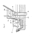
- Fig. 2 einen vergrößerten Ausschnitt aus der Anordnung nach Fig. 1.
- Fig. 1 shows an axial longitudinal section through half of the centrifuge designed according to the invention, the parts which are not important for the invention being shown only schematically and partly with dashed lines.
- FIG. 2 shows an enlarged detail from the arrangement according to FIG. 1.
Die in der Fig. 1 nur zum Teil im Schnitt dargestellte Zentrifuge ist um die lotrechte Achse 1 rotierend antreibbar. Sie weist einen insgesamt mit 2 bezeichneten sich nach oben erweiternden Siebkorb auf, welcher aus einer massiven Wandung 2a und einem darauf im Abstand gehaltenen Sieb 2b besteht und der mit dem in dem dargestellten Beispiel relativ stark ausgebildeten Korbboden 2c fest verbunden, beispielsweise verschweißt ist. Der Siebkorb 2 ist nach oben hin durch einen relativ massiv ausgebildeten Rand 2d abgeschlossen, der ebenfalls mit der Korbwandung 2a in dem dargestellten Beispiel fest verbunden ist.The centrifuge shown only partially in section in FIG. 1 can be driven to rotate about the vertical axis 1. It has a sieve basket, which is denoted overall by 2 and widens upwards, which consists of a
Die mit einem nicht dargestellten Antrieb verbundene Antriebsachse 3 ist in einer ortsfest gehaltenen Stützplatte 4 gelagert und trägt eine in das Korbinnere bzw. in dem dargestellten Beispiel über den Korb 2 hinausragende Nabe 5, welche an ihrem oberen Ende einen Aufgabe- und Verteilertopf 6 trägt, in welchen die zu behandelnde Füllmasse in Richtung des Pfeiles 7 aufgegeben wird. Der Aufgabe- und Verteilertopf 6 ist umschlossen von einer bis in den Bereich des Korbbodens 2c ragenden nach unten konisch erweiterten Vorschleudertrommel 8. Diese besteht ähnlich wie der Siebkorb 2 aus einer massiven Wandung 8a und einem darauf gehaltenen Sieb 8b, einem mit der Wandung fest verbundenen Boden 8c mit einer Durchtrittsöffnung für die Füllmasse und an ihrem erweiterten, dem Korbboden 2c zugewandten Ende einem massiven ringförmigen Rand 8d.The drive shaft 3 connected to a drive, not shown, is held in a stationary
Der ringförmige Rand 8d der Vorschleudertrommel 8 ist umschlossen von einem Einmaischring 9, der seinerseits wiederum von zwei koaxial im Abstand angeordneten weiteren Ringen 10 und 11 umgeben ist, die eine gegensinnige Konizität aufweisen und axial gegeneinander so versetzt angeordnet sind, daß sie sich in ihrer Höhe überdecken.The
Im Bereich zwischen dem Einmaischring 9 und der Wandung 8a der Vorschleudertrommel 8 ist eine Ringleitung 12 angeordnet, die ortsfest gehalten sowie mit einer Zuführungsleitung 13 für die Maischflüssigkeit verbunden ist. Von der Ringleitung 12 gehen über den Umfang verteilt angeordnete, in dem Beispiel rohrförmig ausgebildete Kanäle 14 aus, die im Bereich des ringförmigen Randes 8d der Vorschleudertrommel 8 in Richtung auf den Einmaischring 9 enden.In the area between the
Beim Betrieb der dargestellten Zentrifuge wird die in Richtung des Pfeiles 7 in den Aufgabe- und Verteilertopf 6 überführte Füllmasse beschleunigt, wobei gleichzeitig eine intensive Durchmischung und Homogenisierung erfolgen. Diese Wirkung wird durch die in dem Aufgabe- und Verteilertopf wiedergegebenen Verteiler- und Mitnahmestifte 6a begünstigt. Die über den oberen Rand des Aufgabe- und Verteilertopfes 6 austretende Füllmasse gelangt auf das Sieb 8b der Vorschleudertrommel 8 und wandert von dem Boden 8c der Vorschleudertrommel in Richtung zu dem ringförmigen Rand 8d. Die bei diesem Schleudervorgang von der Füllmasse abgetrennte Flüssigkeit gelangt, wie besonders deutlich aus der Fig. 2 hervorgeht, in einen Ringraum 15 des ringförmigen Randes 8d und verläßt diesen über Abflußrohre 16, welche auf dem Umfang des Bodens 2c des Siebkorbes verteilt angeordnet sind. Die abgeschleuderte Flüssigkeit, welche den Grünablauf bildet, gelangt in einen in Fig. 2 schematisch wiedergegebenen Sammelraum 25, aus dem dieser Grünablauf abgeführt wird.When operating the centrifuge shown, the In the direction of
Die auf dem Sieb 8b der Vorschleudertrommel 8 verbleibende kristalline Masse gelangt über den von dem ringförmigen Rand 8d gebildeten Abwurfrand 17 unter schirm- bzw. schleierartiger Verteilung in Richtung des Pfeiles 18 auf den Einmaischring 9 und wird von dem Einmaischring mitgenommen und weiter in Umfangsrichtung beschleunigt. Dicht oberhalb der Auftreffzone der kristallinen Masse auf den Einmaischring 9 enden die auf dem Umfang verteilt angeordneten rohrförmigen Kanäle 14 für die Zuführung der Einmaischflüssigkeit. Dabei sind die Ausströmöffnungen der rohrförmigen Kanäle 14 in Richtung auf den Einmaischring 9 weisend ausgebildet, d.h. sie sind so angeordnet, daß die austretende Flüssigkeit unmittelbar nach ihrem Aus tritt mit dem Einmaischring 9 in Berührung kommt und von dem Einmaischring dsurch entsprechende Mitnahme in Umfangsrichtung beschleunigt wird. Dabei verteilt sich die Einmaischflüssigkeit filmartig über den unteren Bereich des Einmaischringes 9 und fließt dabei gleichzeitig infolge der Konizität des Einmaischringes 9 in Richtung zu dessen unterem Rand 9a. Durch die Aufgabe der Einmaischflüssigkeit in den Bereich unmittelbar oberhalb der Auftreffzone der kristallinen Masse auf den Einmaischring 9 wird infolge der unterschiedlichen Umfangsgeschwindigkeiten der Flüssigkeit und der auf den Einmaischring auftreffenden Kristalle der Kristallmasse eine intensive Durchmischung der Kristallmasse mit der Einmaischflüssigkeit auf sehr kurzem Wege erreicht, wobei gleichzeitig die Mischung aus Kristallmasse und Einmaischflüssigkeit in Richtung zum unteren Rand 9a des Einmaischringes wandert und von diesem unteren Rand wiederum schirmartig abgeschleudert wird.The crystalline mass remaining on the
Statt der in ausgezogenen Linien wiedergegebenen in Richtung auf den Einmaischring 9 geneigten Anordnung der rohrförmigen Kanäle 14 zur Zuführung der Maischflüssigkeit können diese gemäß der wiedergegebenen gestrichelten Darstellung 14a in Fig. 2 auch als abgewinkelte und nahezu im rechten Winkel auf den Einmaischring 9 ausmündende Kanäle ausgebildet sein. Wichtig ist, daß die Einmaischflüssigkeit dicht oberhalb der Auftreffzone der kristallinen Füllmasse so aufgegeben wird, daß eine filmartige Verteilung in Richtung zu dem unteren Rand 9a des Einmaischringes 9 erreicht wird.Instead of the arrangement of the
Die eingemaischte kristalline Masse gelangt nach ihrem Abschleudern über den unteren Rand 9a in dem wiedergegebenen Beispiel auf den vom Boden 2c des Siebkorbes 2 aufragenden Beschleunigungsring 10, wird vom oberen Rand dieses Ringes erneut schirmartig abgeschleudert und auf den weiteren Beschleunigungsring 11 überführt, von dem die eingemaischte Kristallmasse wiederum schirmartig abgeschleudert und auf das Innere der Siebtrommel 9 gelangt. Die eingemaischte Kristallmasse wird im Zusammenwirken mit der Siebtrommel 2 in bekannter Weise abgeschleudert, wobei auf die Masse im unteren Bereich der Siebtrommel 2 noch eine Deckmittel in Form von Wasser und/ oder Dampf aufgegeben wird.After being spun off, the mashed-in crystalline mass arrives in the
Die von der Kristallmasse abgeschleuderte Flüssigkeit einschl. des Deckmittels gelangt über die Durchtrittsöffnungen 19 bzw. 20 der Wandung 2a des Siebkorbes 2 in einen in Fig. 2 schematisch wiedergegebenen Sammelraum 21, welcher von dem Sammelraum 17 für den Grünablauf getrennt ist.The liquid thrown off by the crystal mass, including the opacifying agent, passes through the through
Die Vorschleudertrommel 8 hat im Vergleich zu Siebkorb 2 einen größeren Öffnungswinkel, wodurch sich eine höhere Bewegungsgeschwindigkeit der aufgegebenen Füllmasse in Richtung zu dem unteren ringförmigen Rand 8d ergibt. Hierdurch wird eine sichere Förderung der aufgegebenen Füllmasse durch die im Betrieb nicht einzusehende Vorschleudertrommel 8 erreicht.The
Gemäß der dargestellten Ausführung ist der Einmaischring 9 im Vergleich zu der Vorschleudertrommel 8 und dem Siebkorb 2 steilkonisch ausgeführt. Hierdurch wird auch bei geringen axialen Wegen der auf den Einmaischring auftreffenden Kristallmasse und der Schmiermittelwirkung des mit der Kristallmasse sich mischenden Filmes der Einmaischflüssigkeit eine hinreichende Verweilzeit der kristallinen Masse und der Einmaischflüssigkeit erreicht. Auf der anderen Seite wird durch den kurzen axialen Weg der Mischung aus der Kristallmasse und der Einmaischflüssigkeit ein Aufbau der Kristalle zu ortsfest auf dem Einmaischring haftenden Klumpen vermieden.According to the embodiment shown, the
Der Einmaischring 9 ist in dem dargestellten Beispiel im Querschnitt L-förmig ausgebildet und im Bereich seines unteren Randes 9a über radial verteilt angeordnete Streben 23 mit dem Boden 2c des Siebkorbes 2 fest verbunden. Hierdurch kann ein freier Zwischenraum zwischen der Vorschleudertrommel 8 und dem Einmaischring 9 geschaffen werden, durch den hindurch sich die ortsfeste Zuleitung 13 für die Maischflüssigkeit erstreckt.In the example shown, the
Der vom Boden 2c des Siebkorbes 2 aufragende Beschleunigungsring 10 ist ebenfalls fest mit dem Boden 2c verbunden, während der außenliegende weitere Beschleunigungsring 11 über radial angeordnete Streben oder eine mit Durchbrechungen ausgebildete Scheibe 24 an der Außenseite des Einmaischringes 9 befestigt, vorzugsweise verschweißt ist.The
Durch die Wirkung der Beschleunigungsringe 10 und 11 werden die durch die Streben 23 beim Abschleudern der eingemaischten kristallinen Masse bei der schirmartigen Verteilung dieser Masse entstehenden Störungen wieder beseitigt und eine gleichmäßige Verteilung auf das Sieb 2b des Siebkorbes 2 erreicht. Statt der wiedergegebenen beiden Beschleunigungsringe 10 und 11 kann auch eine größere Anzahl derartiger Beschleunigungsringe vorgesehen sein, wobei deren Befestigung dann in gleicher Weise möglich ist, wie dieses für die Ringe 10 und11 beschrieben wurde.Due to the action of the acceleration rings 10 and 11, the disturbances caused by the
Als Einmaischflüssigkeit wird zweckmäßig eine weitgehend zuckergesättigte oder übersättigte Lösung verwendet, damit das An- bzw. Auflösen der Kristalle möglichst vermieden wird.A largely sugar-saturated or supersaturated solution is expediently used as the mashing liquid so that the dissolving or dissolving of the crystals is avoided as far as possible.
Die Menge der Einmaischflüssigkeit entspricht nach praktischen Erfahrungen zweckmäßig etwa der Menge, die zuvor durch den Grünablauf von der Füllmasse abgetrennt worden ist, da im Regelfalle der Trockensubstanzgehalt des Grünablaufes etwa dem der Einmaischflüssigkeit entspricht. Wenn die Trockensubstanzgehalte des Grünablaufes und der Einmaischflüssigkeit sehr differieren, so muß durch Änderung des Mengenverhältnisses des Grünablaufes gegenüber der Einmaischflüssigkeit die notwendige Fließfähigkeit der eingemaischten Kristallmasse eingeregelt bzw. erzeugt werden.According to practical experience, the amount of the mash liquid suitably corresponds to the amount that was previously separated from the filling compound by the green drain, since the dry matter content of the green drain generally corresponds to that of the mash liquid. If the dry matter contents of the green runoff and the mashing liquid differ very much, the necessary fluidity of the mashed-in crystal mass must be adjusted or generated by changing the ratio of the green runoff to the mashing liquid.
Claims (9)
Priority Applications (5)
| Application Number | Priority Date | Filing Date | Title |
|---|---|---|---|
| DE8686710003T DE3665993D1 (en) | 1986-01-18 | 1986-01-18 | Continuously operating centrifuge for mingling and centrifuging masse cuites |
| EP86710003A EP0230205B1 (en) | 1986-01-18 | 1986-01-18 | Continuously operating centrifuge for mingling and centrifuging masse cuites |
| JP62003433A JPH0636884B2 (en) | 1986-01-18 | 1987-01-12 | Continuous operation centrifuge for charging and separating underneath sugar and method of operating this centrifuge |
| IN25/MAS/87A IN168780B (en) | 1986-01-18 | 1987-01-16 | |
| US07/183,290 US4802925A (en) | 1986-01-18 | 1988-04-11 | Continuously operable centrifuge for mashing and centrifuging of sugar massecuite |
Applications Claiming Priority (1)
| Application Number | Priority Date | Filing Date | Title |
|---|---|---|---|
| EP86710003A EP0230205B1 (en) | 1986-01-18 | 1986-01-18 | Continuously operating centrifuge for mingling and centrifuging masse cuites |
Publications (2)
| Publication Number | Publication Date |
|---|---|
| EP0230205A1 true EP0230205A1 (en) | 1987-07-29 |
| EP0230205B1 EP0230205B1 (en) | 1989-10-04 |
Family
ID=8196433
Family Applications (1)
| Application Number | Title | Priority Date | Filing Date |
|---|---|---|---|
| EP86710003A Expired EP0230205B1 (en) | 1986-01-18 | 1986-01-18 | Continuously operating centrifuge for mingling and centrifuging masse cuites |
Country Status (5)
| Country | Link |
|---|---|
| US (1) | US4802925A (en) |
| EP (1) | EP0230205B1 (en) |
| JP (1) | JPH0636884B2 (en) |
| DE (1) | DE3665993D1 (en) |
| IN (1) | IN168780B (en) |
Cited By (2)
| Publication number | Priority date | Publication date | Assignee | Title |
|---|---|---|---|---|
| DE3828204A1 (en) * | 1988-08-19 | 1990-02-22 | Braunschweigische Masch Bau | Continuously operating centrifuge for mingling and spinning off massecuite |
| EP0487781A1 (en) * | 1990-11-30 | 1992-06-03 | Braunschweigische Maschinenbauanstalt AG | Continuously operating centrifugal strainer for sugar massecuites |
Families Citing this family (1)
| Publication number | Priority date | Publication date | Assignee | Title |
|---|---|---|---|---|
| US5720880A (en) * | 1995-07-03 | 1998-02-24 | California Pellet Mill Company | Sugar centrifugal screen saver |
Citations (2)
| Publication number | Priority date | Publication date | Assignee | Title |
|---|---|---|---|---|
| GB2064351A (en) * | 1979-12-04 | 1981-06-17 | Braunschweigische Masch Bau | Continuously operating centrifugal strainer for sugar massecuites |
| AU544238B2 (en) * | 1981-04-15 | 1985-05-23 | Lehmann Hein A.G. | Apparatus for separating a fillmass or massecuite by centrifugal force |
Family Cites Families (4)
| Publication number | Priority date | Publication date | Assignee | Title |
|---|---|---|---|---|
| DE2333122C2 (en) * | 1973-06-29 | 1985-08-01 | Salzgitter Maschinen Und Anlagen Ag, 3320 Salzgitter | Device for actuating a closure body of a centrifuge |
| FR2245415B1 (en) * | 1973-10-02 | 1978-09-29 | Fives Cail Babcock | |
| US3970470A (en) * | 1974-10-18 | 1976-07-20 | Hein, Lehmann A.G. | Centrifuge |
| DE2936659A1 (en) * | 1979-09-11 | 1981-03-19 | Braunschweigische Maschinenbauanstalt AG, 3300 Braunschweig | CONTINUOUSLY WORKING SUGAR CENTRIFUGE |
-
1986
- 1986-01-18 EP EP86710003A patent/EP0230205B1/en not_active Expired
- 1986-01-18 DE DE8686710003T patent/DE3665993D1/en not_active Expired
-
1987
- 1987-01-12 JP JP62003433A patent/JPH0636884B2/en not_active Expired - Lifetime
- 1987-01-16 IN IN25/MAS/87A patent/IN168780B/en unknown
-
1988
- 1988-04-11 US US07/183,290 patent/US4802925A/en not_active Expired - Fee Related
Patent Citations (2)
| Publication number | Priority date | Publication date | Assignee | Title |
|---|---|---|---|---|
| GB2064351A (en) * | 1979-12-04 | 1981-06-17 | Braunschweigische Masch Bau | Continuously operating centrifugal strainer for sugar massecuites |
| AU544238B2 (en) * | 1981-04-15 | 1985-05-23 | Lehmann Hein A.G. | Apparatus for separating a fillmass or massecuite by centrifugal force |
Cited By (2)
| Publication number | Priority date | Publication date | Assignee | Title |
|---|---|---|---|---|
| DE3828204A1 (en) * | 1988-08-19 | 1990-02-22 | Braunschweigische Masch Bau | Continuously operating centrifuge for mingling and spinning off massecuite |
| EP0487781A1 (en) * | 1990-11-30 | 1992-06-03 | Braunschweigische Maschinenbauanstalt AG | Continuously operating centrifugal strainer for sugar massecuites |
Also Published As
| Publication number | Publication date |
|---|---|
| EP0230205B1 (en) | 1989-10-04 |
| US4802925A (en) | 1989-02-07 |
| IN168780B (en) | 1991-06-01 |
| JPS62216656A (en) | 1987-09-24 |
| JPH0636884B2 (en) | 1994-05-18 |
| DE3665993D1 (en) | 1989-11-09 |
Similar Documents
| Publication | Publication Date | Title |
|---|---|---|
| DE2750696A1 (en) | MULTI-STAGE PROCESS AND DEVICE FOR APPLYING A SPRAYABLE AGENT TO A MATERIAL MADE FROM LOOSE GRANULATE, SCALED, CHIP OR FIBER PARTICLES | |
| DE2207663C3 (en) | Continuously working sugar centrifuge | |
| DE2550496B2 (en) | Process and centrifuge for spinning off and redissolving sugar | |
| CH622341A5 (en) | ||
| DE3415519C2 (en) | ||
| EP0230205B1 (en) | Continuously operating centrifuge for mingling and centrifuging masse cuites | |
| DE2834491C2 (en) | Sieve centrifuge with curved sieve pockets | |
| DE2025828B2 (en) | CONTINUOUSLY OPERATING CENTRIFUGE | |
| EP0487780B1 (en) | Continuously operating centrifugal strainer for sugar massecuites | |
| DE2608911A1 (en) | CONTINUOUSLY OPERATING SUGAR CENTRIFUGE, IN PARTICULAR FOR MEDIUM PRODUCT AND / OR WHITE SUGAR FILLING MASS | |
| EP0163112B1 (en) | Method and device for the centrifugal separation of fine-grained mineral mixtures | |
| DE3615224C2 (en) | ||
| DE2328830A1 (en) | CENTRIFUGE, IN PARTICULAR SUGAR CENTRIFUGE | |
| DE2803160A1 (en) | CONTINUOUSLY WORKING CENTERS | |
| EP2429711B1 (en) | Continuous centrifuge | |
| DE3933136C2 (en) | ||
| DE3828204C2 (en) | ||
| EP0263285B1 (en) | Continuously operating sugar centrifuge | |
| EP0455964B1 (en) | Centrifuge | |
| DE2930312C2 (en) | Sieve centrifuge | |
| DE951140C (en) | Sieve centrifuge for removing liquids from thick matter | |
| DE505249C (en) | Uninterrupted spinner for raw sugar | |
| DE2306302B2 (en) | Centrifuge rotor with paddle-like curved sieve surfaces arranged around its axis | |
| DE1482717B1 (en) | Method and centrifuge for centrifuging sugar masses | |
| DE1482717C (en) | Process and centrifuge for centrifuging sugar masses |
Legal Events
| Date | Code | Title | Description |
|---|---|---|---|
| PUAI | Public reference made under article 153(3) epc to a published international application that has entered the european phase |
Free format text: ORIGINAL CODE: 0009012 |
|
| AK | Designated contracting states |
Kind code of ref document: A1 Designated state(s): DE FR GB IT SE |
|
| 17P | Request for examination filed |
Effective date: 19870903 |
|
| 17Q | First examination report despatched |
Effective date: 19881028 |
|
| GRAA | (expected) grant |
Free format text: ORIGINAL CODE: 0009210 |
|
| AK | Designated contracting states |
Kind code of ref document: B1 Designated state(s): DE FR GB IT SE |
|
| REF | Corresponds to: |
Ref document number: 3665993 Country of ref document: DE Date of ref document: 19891109 |
|
| GBT | Gb: translation of ep patent filed (gb section 77(6)(a)/1977) | ||
| ET | Fr: translation filed | ||
| PGFP | Annual fee paid to national office [announced via postgrant information from national office to epo] |
Ref country code: SE Payment date: 19891211 Year of fee payment: 5 |
|
| ITF | It: translation for a ep patent filed | ||
| PLBE | No opposition filed within time limit |
Free format text: ORIGINAL CODE: 0009261 |
|
| STAA | Information on the status of an ep patent application or granted ep patent |
Free format text: STATUS: NO OPPOSITION FILED WITHIN TIME LIMIT |
|
| 26N | No opposition filed | ||
| PG25 | Lapsed in a contracting state [announced via postgrant information from national office to epo] |
Ref country code: SE Effective date: 19910119 |
|
| ITTA | It: last paid annual fee | ||
| EUG | Se: european patent has lapsed |
Ref document number: 86710003.4 Effective date: 19910910 |
|
| PGFP | Annual fee paid to national office [announced via postgrant information from national office to epo] |
Ref country code: FR Payment date: 19961129 Year of fee payment: 12 |
|
| PGFP | Annual fee paid to national office [announced via postgrant information from national office to epo] |
Ref country code: GB Payment date: 19970109 Year of fee payment: 12 |
|
| PGFP | Annual fee paid to national office [announced via postgrant information from national office to epo] |
Ref country code: DE Payment date: 19970115 Year of fee payment: 12 |
|
| PG25 | Lapsed in a contracting state [announced via postgrant information from national office to epo] |
Ref country code: GB Free format text: LAPSE BECAUSE OF NON-PAYMENT OF DUE FEES Effective date: 19980118 |
|
| PG25 | Lapsed in a contracting state [announced via postgrant information from national office to epo] |
Ref country code: FR Free format text: THE PATENT HAS BEEN ANNULLED BY A DECISION OF A NATIONAL AUTHORITY Effective date: 19980131 |
|
| GBPC | Gb: european patent ceased through non-payment of renewal fee |
Effective date: 19980118 |
|
| PG25 | Lapsed in a contracting state [announced via postgrant information from national office to epo] |
Ref country code: DE Free format text: LAPSE BECAUSE OF NON-PAYMENT OF DUE FEES Effective date: 19981001 |
|
| REG | Reference to a national code |
Ref country code: FR Ref legal event code: ST |
|
| PG25 | Lapsed in a contracting state [announced via postgrant information from national office to epo] |
Ref country code: IT Free format text: LAPSE BECAUSE OF NON-PAYMENT OF DUE FEES;WARNING: LAPSES OF ITALIAN PATENTS WITH EFFECTIVE DATE BEFORE 2007 MAY HAVE OCCURRED AT ANY TIME BEFORE 2007. THE CORRECT EFFECTIVE DATE MAY BE DIFFERENT FROM THE ONE RECORDED. Effective date: 20050118 |