EP0229846A1 - Process for producing silicon steel sheet having soft magnetic characteristics - Google Patents
Process for producing silicon steel sheet having soft magnetic characteristics Download PDFInfo
- Publication number
- EP0229846A1 EP0229846A1 EP86903601A EP86903601A EP0229846A1 EP 0229846 A1 EP0229846 A1 EP 0229846A1 EP 86903601 A EP86903601 A EP 86903601A EP 86903601 A EP86903601 A EP 86903601A EP 0229846 A1 EP0229846 A1 EP 0229846A1
- Authority
- EP
- European Patent Office
- Prior art keywords
- rolling
- hot
- temperature
- cold
- roughing
- Prior art date
- Legal status (The legal status is an assumption and is not a legal conclusion. Google has not performed a legal analysis and makes no representation as to the accuracy of the status listed.)
- Granted
Links
Images
Classifications
-
- C—CHEMISTRY; METALLURGY
- C21—METALLURGY OF IRON
- C21D—MODIFYING THE PHYSICAL STRUCTURE OF FERROUS METALS; GENERAL DEVICES FOR HEAT TREATMENT OF FERROUS OR NON-FERROUS METALS OR ALLOYS; MAKING METAL MALLEABLE, e.g. BY DECARBURISATION OR TEMPERING
- C21D8/00—Modifying the physical properties by deformation combined with, or followed by, heat treatment
- C21D8/12—Modifying the physical properties by deformation combined with, or followed by, heat treatment during manufacturing of articles with special electromagnetic properties
- C21D8/1216—Modifying the physical properties by deformation combined with, or followed by, heat treatment during manufacturing of articles with special electromagnetic properties the working step(s) being of interest
- C21D8/1222—Hot rolling
Definitions
- the present invention relates to an improvement of a method of producing high silicon iron sheet of more than 4wt% Si having excellent soft magnetic properties by hot rolling and cold rolling processes.
- Silicon iron alloys have excellent soft magnetic properties, and have been much used as magnetic cores of electric transformers or material for other electric devices. It is known that the more is Si content, the more improved are the soft magnetic properties, and these properties show peaks at around 6.5wt%. However since, if Si content were more than 4.0wt%, an elongation would be rapidly decreased, and ordinary cold rolling could not be practised. Therefore it has been regarded as impossible to industrially produce sheet containing Si of more than 4wt%.
- This invention has been developed in view of such circumstances, and is to provide a method of effectively producing high silicon iron sheets of more than 4wt% Si via the rolling processes.
- a molten Fe alloy is produced, which comprises Si: 4.0 to 7.0wt%, Mn: not more than 0.5wt%, P: not more than 0.lwt%, S: not more than 0.02wt% and Al: not more than 2wt%.
- the produced alloy is made an ingot or slab by a continuous casting, subjected to a slabbing-roughing, or a roughing at temperature of more than 1000°C and at total reduction of more than 50%, performed thereon with at hot finish rolling under conditions specified as follows, and coiled at temperature of not more than 750°C.
- the oxide scale ot the hot rolled strip or plate is removed by pickling or grinding, and after trimming if required, entered to a cold rolling.
- the cold rolled strip or sheet is subjected to an annealing for improving the magnetic properties.
- the annealing is done at temperature of the cold rolled strip or sheet being more than 800°C.
- the most noted thing in the invention is said hot finish rolling at temperature of not more than 1100°C and the total reduction R(%), and the coiling at not more than 750°C .
- the total reduction R(%) is defined as follows.
- the inventors made many experimental studies on an improvement of cold workability with respect to the above mentioned high silicon iron alloys, and found that if selecting the hot finish rolling conditions in response to an microstructure before the hot finish rolling, a hot rolled plate having excellent cold workability might be produced, and that the cold workability of silicon iron alloys was regulated by a microstructural parameter of the hot rolled plate.
- Fig.l shows the cold workability of 6.5% silicon iron alloy, in which lateral and vertical axes indicate the average grain diameter d(mm) before hot finish rolling and the total reduction R(%) of the hot finish rolling respectively.
- the figure was obtained by investigating the samples with various average grain diameter, which were prepared from the 50kg ingots.
- the samples were soaked at temperature of 1000°C, and hot-rolled by 6 passes to each amount of the total reduction.
- the finish temperature was 650 10°C.
- 0 indicates that no edge cracks generated when the hot-rolled plates were cold-rolled at the total reduction of 85%, in other words, the cold workablity was preferable.
- x indicates that the cracks generated at beginning of said cold rolling and further rolling was impossible.
- the microstructure obtained by said hot finish rolling is fibrous or lamellar where the grains are elongated in the rolling direction, while polygonal is the microstructure when the total reduction at the hot finish rolling is zero. From this result, it is seen that if a microstructural parameter, that is, average spacings ⁇ (mm) between grain bound- ries in the direction of plate thickness were introduced, irrespectively of differences in the morphology of microstructure, general cold workablity could be explained by ⁇ .
- ⁇ corresponds to the average grain diameter in thickness direction when the structure is fibrous or lamellar, and when it is polygonal, 1 becomes the same as the average grain diameter which is usually defined.
- the recrystallizing temperature of this kind of alloys is 1000 to 1100°C.
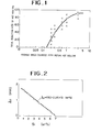
- ⁇ 0.2mm is assumed as a critical value and expressed with 10, ⁇ 0 is varied by Si content. That is, when ⁇ 0 was gained by the same experiment as Fig.l with respect to the alloys of 1 to 6wt% Si, a result was shown in Fig.2. If ⁇ 4 is expressed as a function of Si content from said result,
- the microstructure of the high silicon iron alloy could be refined without generating crackings. If the alloy is subjected to the slabbing or the roughing prior to the hot finish rolling under the above mentioned conditions, it is possible to produce an intermediate material (for example, roughed bar material) to be entered to the hot finish rolling by using the ingot or the continuously cast slab.
- an intermediate material for example, roughed bar material
- Si is an element which improves the soft magnetic properties, and it displays the most excellent effect at around 6.5wt%.
- the invention specifies Si content 4.0 to 7.0wt%. If Si were less than 4.0wt%, no problem would occur about the cold workability, and if it were more than 7.0wt%, soft magnetic properties would be deteriorated through increment of magnetostriction and decrement of saturation induction and maximum permeability and in addition, cold workability would be extremely bad. Thus, the range of Si is 4.0 to 7.0wt%.
- Mn is added to fix S as an impurity. But if Mn content were increased, the workability would be worsened and if MnS were increased, bad influences would be given to the soft magnetic properties, hence Mn s 0.5wt%.
- S is required to be lessened as possible as mentioned above, and the invention specifies S ⁇ 0.02wt%.
- Al is added for deoxidation at preparing the molten steel. Further, it is known that Al fixes solute N which deteriorates the soft magnetic properties, and electric resistance is increased. By adding enough Al it is possible to coarsen the size of precipitated AlN until it has scarecely resistance against moving of magnetic domain wall. However, if Al were added too much, the cold workability would be made bad, and a cost-up would be invited, and therefore it is A1 ⁇ 2wt%.
- C is a halmful element which increases the iron loss and is a main factor of a magnetic aging, and is desirous to be less. But since C enlarges r loop of Fe-Si equilibrium diagram, and r - ⁇ transformation point appears during cooling if an apt amount to be determined by Si content is added, a heating treatment utilizing said transformation would be possible. Therefore, it is preferable that C is not more than lwt%.
- the cast alloy is undertaken with the slabbing and roughing if it is an ingot, and it is done with the roughing if it is a continuously cast slab.
- These rolling conditins are decided for performing the refinement by recrystallization.
- the recrystallization does not take place at the temperatures of less than 1000°C, and if the rolling were forcibly carried out at ranges of said temperatures, cracks would be created, and therefore the rolling temperautre is more than 1000°C.
- strain of more than 50% is required, and the total reduction be specified more than 50%.
- the rolling should be begun at the temperature of not more than 1100°C. If the total reduction is assumed as R(), ⁇ is geometrically decided by d and R, and so R z (1 - 1 0/ d) x 100(%) is required for satisfying ⁇ 0 . However, if d ⁇ ⁇ 0 is obtained by the roughing or other means, the hot finish rolling is not necessary in view of the cold workability. But the rolling is necessary in the practical requires or, and in such a case, the reduction is R ⁇ 0. In the case of polygonal microstructure, the cold rolling is also possible if ⁇ ⁇ ⁇ 0 is realized.
- a reason for specifying the coiling temperature of-not more than 750°C is why the recrystallization and the grain growth happen during cooling the coil if coiling more than 750°C.
- Warm rolling in which temperature of rolled sheet is less than 400°C, is also possible instead of the cold rolling on the hot rolled plates, and such a warm rolling is effective to improve the workability.
- the annealing after the cold or warm rolling is carried out for imparting magnetic properties to the silicon iron sheet, and the annealing is done at the temperature of the sheet being more than 800°C. If the annealing temperature were less than 800°C, the excellent magnetic properties would not be provided since the crystal grains are too fine.
- annealing it is possible to carry out the annealing on the hot rolled plate at the temperature of not more than 750°C before the cold rolling, otherwise carry out an intermediate annealing at the temperature of not more than 750°C in the course of the cold rolling.
- These annealings are for improving the cold workability and accomplishing decarburization, and the both are done if required.
- Fig. 1 is a graph showing a range where no cracks are generated in a relation between the average grain diameter before the hot finish rolling and the total reduction during the hot finish rolling;
- Fig.2 is a graph showing a relation between Si content and A.
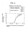
- Fig.3 is a graph showing a scope realized in the embodiment where the cold rolling is possible.
- the continuously cast slabs (thickness: 200mm) having the chemical composition shown in Table 1 were heated at the temperatures of 1200°C and 1300°C for 3 hours respectively, immediately followed by the roughing.
- the roughings were performed by 5 passes, and the slabs were practised with pass shedules of each 3 levels for charging the grain size. Subsequently, these materials were heated at the temperature of 900°C and, after 30 minutes, entered into the hot finish rolling.
- the objective finish thicknesses were selected by each several standards in response to the average grain sizes of the roughed bar materials with reference to the result of Fig.l.
- the finishing temperatures were 775 to 680°C and the coiling temperatures were 655 to 610°C.
- High silicon iron alloys having the chemical composition shown in Table 3 were molten in the vacuum melting furnace and cast into ingots. Those ingots were soaked at the temperature of 1150°C and slabbed (the total reduction: 64%) into 180mm thickness and further soaked at the temperature of 1150°C and roughed (the total reduction: 81%) into 35mm thickness and hot rolled to an objective finish thickness of 3mm (the total reduction: 91%). The finishing temperature was 765 ⁇ 10°C and the coiling temperature was 670 ⁇ 5°C. Those hot rolled coils were pickled and cold-rolled to 0.5mm thickness. Table 4 shows the average grain diameters of crop samples of the roughed bars, the average spacings of the grain boundaries and the tested results of the cold workability. With respect to the cold workability, the 0 marks show the rollings to 0.5mm thickness without causing cracks, while the X marks show the heavy defects or breakages of the strips.
- Table 4 show the result that although the microstructures of the hot rolled plates satisfy the conditions of ⁇ ⁇ ⁇ 0 , the cold rollings could not be carried out due to the chemical compositions. (Example 3)
- the continuously cast slabs (thickness: 200mm) having the chemical composition shown in Table 1 were heated at the temperature of 1200°C for'3 hours, immediately followed by the roughing at the temperature of 1008°C at the exit sides to 30mm thickness (the total reduction: 85%).
- the grain size after the roughing was 1.2mm.
- the hot finish rolling with the total reduction of 90% was 90% performed at the surface temperature of 950°C.
- the finishing temperature was 850°C and the coiling temperature was 680°C.
- a sample was cut out from the hot rolled coil, and the measured average spacing of the grain boundaries were 0.12mm.
- the hot rolled coil was pickled and 83% cold-rolled to 0.5mm thickness, and undertaken with a box annealing at the temperature of 1000°C (H 2 atmosphere) and measured with AC magnetic properties. Table 5 shows the measured results.
- Silicon iron alloys having the chemical composition of Table 7 were molten in the vacuum melting furnace, and cast into ingots and soaked at the temperature of l180°C for 3 hours, and slabbed (the total reduction: 60%) into 200mm thickness, and further soaked at the temperature of 1180°C for 1 hour and roughed to 35mm thickness and finished to 2.4mm in thickness. Those coils were pickled with hydrochloric acid and cold-rolled, and the cold workability was measured with the same appreciations as Example 1.
- Fig.8 shows the hot rolling conditions, the average grain size of crop samples after roughing, the hot finish rolled plate and the appreciated results of the cold workability.
- This high silicon iron sheet produced by the method of the invention are used as magnetic cores of the electric transformers or materials for other electric devices.
Abstract
Description
- The present invention relates to an improvement of a method of producing high silicon iron sheet of more than 4wt% Si having excellent soft magnetic properties by hot rolling and cold rolling processes.
- Silicon iron alloys have excellent soft magnetic properties, and have been much used as magnetic cores of electric transformers or material for other electric devices. It is known that the more is Si content, the more improved are the soft magnetic properties, and these properties show peaks at around 6.5wt%. However since, if Si content were more than 4.0wt%, an elongation would be rapidly decreased, and ordinary cold rolling could not be practised. Therefore it has been regarded as impossible to industrially produce sheet containing Si of more than 4wt%.
- This invention has been developed in view of such circumstances, and is to provide a method of effectively producing high silicon iron sheets of more than 4wt% Si via the rolling processes.
- In the invention, a molten Fe alloy is produced, which comprises Si: 4.0 to 7.0wt%, Mn: not more than 0.5wt%, P: not more than 0.lwt%, S: not more than 0.02wt% and Al: not more than 2wt%. The produced alloy is made an ingot or slab by a continuous casting, subjected to a slabbing-roughing, or a roughing at temperature of more than 1000°C and at total reduction of more than 50%, performed thereon with at hot finish rolling under conditions specified as follows, and coiled at temperature of not more than 750°C. The oxide scale ot the hot rolled strip or plate is removed by pickling or grinding, and after trimming if required, entered to a cold rolling. The cold rolled strip or sheet is subjected to an annealing for improving the magnetic properties. The annealing is done at temperature of the cold rolled strip or sheet being more than 800°C.
- The most noted thing in the invention is said hot finish rolling at temperature of not more than 1100°C and the total reduction R(%), and the coiling at not more than 750°C .
- The total reduction R(%) is defined as follows.
- Assuming that d(mm) is an average grain diameter before the hot finish rolling, and when λ0 is given by a following equation of

- if d > λ0, R(%) ≥ (1 - λ0/d) x 100, and if d ≤ λ0, R(%) ≥ 0.
- Herein, if R(%) = 0, the hot finish rolling is not of course carried out, and this invention also includes such a case.
- The invention will be explained in detail.
- The inventors made many experimental studies on an improvement of cold workability with respect to the above mentioned high silicon iron alloys, and found that if selecting the hot finish rolling conditions in response to an microstructure before the hot finish rolling, a hot rolled plate having excellent cold workability might be produced, and that the cold workability of silicon iron alloys was regulated by a microstructural parameter of the hot rolled plate.
- Fig.l shows the cold workability of 6.5% silicon iron alloy, in which lateral and vertical axes indicate the average grain diameter d(mm) before hot finish rolling and the total reduction R(%) of the hot finish rolling respectively.
- The figure was obtained by investigating the samples with various average grain diameter, which were prepared from the 50kg ingots. The samples were soaked at temperature of 1000°C, and hot-rolled by 6 passes to each amount of the total reduction. The finish temperature was 650 10°C.
- In the figure, 0 indicates that no edge cracks generated when the hot-rolled plates were cold-rolled at the total reduction of 85%, in other words, the cold workablity was preferable. x indicates that the cracks generated at beginning of said cold rolling and further rolling was impossible.
- From this figure, it is obvious that when the average grain diameter d(mm) before the hot finish rolling is large, large hot rolling reduction is necessary to undertake the cold rolling (for example, when the average grain diameter is 3mm, the total hot rolling reduction of more than 95% is necessary), and on the other hand, if the average grain diameter were small, the cold rolling would be possible even if the reduction at the hot finish rolling were small (for example, when the average grain diameter is 0.32mm, the cold rolling is possible even if the total reduction is 40%).
- In addition, if said average grain diameter were less than a certain determined value, the cold rolling would be possible without the hot finish rolling.
- The microstructure obtained by said hot finish rolling is fibrous or lamellar where the grains are elongated in the rolling direction, while polygonal is the microstructure when the total reduction at the hot finish rolling is zero. From this result, it is seen that if a microstructural parameter, that is, average spacings λ(mm) between grain bound- ries in the direction of plate thickness were introduced, irrespectively of differences in the morphology of microstructure, general cold workablity could be explained by λ. λ corresponds to the average grain diameter in thickness direction when the structure is fibrous or lamellar, and when it is polygonal, 1 becomes the same as the average grain diameter which is usually defined. The recrystallizing temperature of this kind of alloys is 1000 to 1100°C. Therefore, 1 of the fabrous structure provided by the hot finish rolling at the starting temperature of not more than 1100°C, quite agrees to a value calculated by the average grain diameter before the hot finish rolling and the total hot rolling reduction, since the recrystallization scarecely takes place in said temperature range and the grains are only crashed evenly in the thickness. A curve of Fig.l shows calculated total reduction of the hot finish rolling, as λ becomes 0.2mm. This curve shows a very good agreement to boundaries between the cold rolling possible range and impossible range. From this fact it is seen that the cold rolling is possible by lowering λ below 0.2mm in the 6.5wt% silicon iron alloy, irrespectively of shapes of crystal grains. If λ = 0.2mm is assumed as a critical value and expressed with 10, λ0 is varied by Si content. That is, when λ0 was gained by the same experiment as Fig.l with respect to the alloys of 1 to 6wt% Si, a result was shown in Fig.2. If λ4 is expressed as a function of Si content from said result,

- From the above mentioned result, it was possible to clarify the hot finish rolling conditions for producing the hot rolled plate suitable to the cold rolling. However the average grain diameters of the ingots or the continuously cast slabs ordinarily produced are large, and in order to refine the average spacings between the grain boundaries in the thickness direction less than λ0, the total reduction thereof must be extremely large, and in such a condition the ingot or slab is frequently cracked. Therefore, it is necessary to refine the microstructure of the ingot or the continuously cast slab prior to the hot finish rolling. By forming the fibrous (lamellar) structure, the refinement to a certain extent could be accomplished, but if utilizing the recrystallization, the refinement could be more effectively carried out. In the inventors' studies, if the hot rolling of more than 50% was done at the temperature of more than 1000°C, the microstructure of the high silicon iron alloy could be refined without generating crackings. If the alloy is subjected to the slabbing or the roughing prior to the hot finish rolling under the above mentioned conditions, it is possible to produce an intermediate material (for example, roughed bar material) to be entered to the hot finish rolling by using the ingot or the continuously cast slab.
- The above mentioned findings may be summerized as under
- (1) The cold workability of the high silicon iron alloy depends upon the average spacings λ(mm) between the grain boundaries in the thickness direction prior to the cold rolling.
- (2) If said spacings are made less than a certain critical value ¡O (mm) which is determined by the Si content, an excellent cold workablity could be provided.
- (3) The hot finish rolling conditions are specified so as to realize the above mentioned λ0, and they must be decided in response to the average grain diameter d (mm) prior to the hot finish rolling. That is, in the hot finish rolling at the temperature of below 1100°C where the recrystallization does not take place, the reduction should be made by a value {(1 - λ0/d x 100(%)} which is decided geometrically from the values of λ0 and d.
- (4) For realizing said hot finish rolling, the refinement through the roughing or slabbing is required, and it is accomplished by the rolling at the temperature of above 1000°C and at the total reduction of more than 50%.
- (5) If the average spacings between the grain boundaries in the thickness direction of less than said λ0(mm) were obtained by the roughing or slabbing conditions, the material per se displays the excellent cold workability (not undertaking the hot finish hot rolling).
- This invention is based on the above mentioned concept, and references will be made in detail to the specifying conditions and others.
- Si is an element which improves the soft magnetic properties, and it displays the most excellent effect at around 6.5wt%. The invention specifies Si content 4.0 to 7.0wt%. If Si were less than 4.0wt%, no problem would occur about the cold workability, and if it were more than 7.0wt%, soft magnetic properties would be deteriorated through increment of magnetostriction and decrement of saturation induction and maximum permeability and in addition, cold workability would be extremely bad. Thus, the range of Si is 4.0 to 7.0wt%.
- Mn is added to fix S as an impurity. But if Mn content were increased, the workability would be worsened and if MnS were increased, bad influences would be given to the soft magnetic properties, hence Mn s 0.5wt%.
- P lowers iron loss. However, if P content were increased, the workablity would be worsened and it is specified as P s O.lwt%.
- S is required to be lessened as possible as mentioned above, and the invention specifies S ≤ 0.02wt%.
- Al is added for deoxidation at preparing the molten steel. Further, it is known that Al fixes solute N which deteriorates the soft magnetic properties, and electric resistance is increased. By adding enough Al it is possible to coarsen the size of precipitated AlN until it has scarecely resistance against moving of magnetic domain wall. However, if Al were added too much, the cold workability would be made bad, and a cost-up would be invited, and therefore it is A1 ≤ 2wt%.
- C is a halmful element which increases the iron loss and is a main factor of a magnetic aging, and is desirous to be less. But since C enlarges r loop of Fe-Si equilibrium diagram, and r - α transformation point appears during cooling if an apt amount to be determined by Si content is added, a heating treatment utilizing said transformation would be possible. Therefore, it is preferable that C is not more than lwt%.
- The cast alloy is undertaken with the slabbing and roughing if it is an ingot, and it is done with the roughing if it is a continuously cast slab. These rolling conditins are decided for performing the refinement by recrystallization. In a slab of silicon iron alloy, the recrystallization does not take place at the temperatures of less than 1000°C, and if the rolling were forcibly carried out at ranges of said temperatures, cracks would be created, and therefore the rolling temperautre is more than 1000°C. Further, for accomplishing satisfied refinement, strain of more than 50% is required, and the total reduction be specified more than 50%.
- As having mentioned, basing on a premise that the fibrous (or lamellar) microstructure, the rolling should be begun at the temperature of not more than 1100°C. If the total reduction is assumed as R(), λ is geometrically decided by d and R, and so R z (1 - 10/d) x 100(%) is required for satisfying λ≤λ0. However, if d ≤ λ0 is obtained by the roughing or other means, the hot finish rolling is not necessary in view of the cold workability. But the rolling is necessary in the practical requires or, and in such a case, the reduction is R ≥ 0. In the case of polygonal microstructure, the cold rolling is also possible if λ ≤ λ0 is realized.
- A reason for specifying the coiling temperature of-not more than 750°C is why the recrystallization and the grain growth happen during cooling the coil if coiling more than 750°C.
- Warm rolling in which temperature of rolled sheet is less than 400°C, is also possible instead of the cold rolling on the hot rolled plates, and such a warm rolling is effective to improve the workability.
- The annealing after the cold or warm rolling is carried out for imparting magnetic properties to the silicon iron sheet, and the annealing is done at the temperature of the sheet being more than 800°C. If the annealing temperature were less than 800°C, the excellent magnetic properties would not be provided since the crystal grains are too fine.
- Apart from the above mentioned annealing, it is possible to carry out the annealing on the hot rolled plate at the temperature of not more than 750°C before the cold rolling, otherwise carry out an intermediate annealing at the temperature of not more than 750°C in the course of the cold rolling. These annealings are for improving the cold workability and accomplishing decarburization, and the both are done if required.
- Fig. 1 is a graph showing a range where no cracks are generated in a relation between the average grain diameter before the hot finish rolling and the total reduction during the hot finish rolling; Fig.2 is a graph showing a relation between Si content and A. and Fig.3 is a graph showing a scope realized in the embodiment where the cold rolling is possible.
- The continuously cast slabs (thickness: 200mm) having the chemical composition shown in Table 1 were heated at the temperatures of 1200°C and 1300°C for 3 hours respectively, immediately followed by the roughing. The roughings were performed by 5 passes, and the slabs were practised with pass shedules of each 3 levels for charging the grain size. Subsequently, these materials were heated at the temperature of 900°C and, after 30 minutes, entered into the hot finish rolling. The objective finish thicknesses were selected by each several standards in response to the average grain sizes of the roughed bar materials with reference to the result of Fig.l. The finishing temperatures were 775 to 680°C and the coiling temperatures were 655 to 610°C. The hot finish rolled strips were subjected to the cold rolling after the pickling, and the cold workability was tested as in Fig.l. The roughing and the hot rolling conditions and the measured values of the average grain size are shown in Table 2, and the tested results of the cold workability are shown in Fig.3. 0 marks in Fig.3 show that the cold rollings were done without causing cracks, while X marks show that heavy defects occurred or the strips were broken. Further, a curve in the same shows conditions that the spacings between the gain boundaries are 10 = 0.2mm as in Fig.l. It was confirmed therefrom that the tendency obtained in Fig.l will be obtained in the actually practising operations.


- High silicon iron alloys having the chemical composition shown in Table 3 were molten in the vacuum melting furnace and cast into ingots. Those ingots were soaked at the temperature of 1150°C and slabbed (the total reduction: 64%) into 180mm thickness and further soaked at the temperature of 1150°C and roughed (the total reduction: 81%) into 35mm thickness and hot rolled to an objective finish thickness of 3mm (the total reduction: 91%). The finishing temperature was 765 ± 10°C and the coiling temperature was 670 ± 5°C. Those hot rolled coils were pickled and cold-rolled to 0.5mm thickness. Table 4 shows the average grain diameters of crop samples of the roughed bars, the average spacings of the grain boundaries and the tested results of the cold workability. With respect to the cold workability, the 0 marks show the rollings to 0.5mm thickness without causing cracks, while the X marks show the heavy defects or breakages of the strips.
- Table 4 show the result that although the microstructures of the hot rolled plates satisfy the conditions of λ ≤ λ0, the cold rollings could not be carried out due to the chemical compositions.


- The continuously cast slabs (thickness: 200mm) having the chemical composition shown in Table 1 were heated at the temperature of 1200°C for'3 hours, immediately followed by the roughing at the temperature of 1008°C at the exit sides to 30mm thickness (the total reduction: 85%). The grain size after the roughing was 1.2mm. The hot finish rolling with the total reduction of 90% was 90% performed at the surface temperature of 950°C. The finishing temperature was 850°C and the coiling temperature was 680°C. After the hot rolling, a sample was cut out from the hot rolled coil, and the measured average spacing of the grain boundaries were 0.12mm. The hot rolled coil was pickled and 83% cold-rolled to 0.5mm thickness, and undertaken with a box annealing at the temperature of 1000°C (H2 atmosphere) and measured with AC magnetic properties. Table 5 shows the measured results.

- If Si content were more than 4wt%, the effect of cooling in a magnetic field becomes remarkable. Therefore, a sample cut from the coil was annealed at 800°C for 10min, and given the magnetizing field of 200 Oe during the subsequent cooling, and AC magnetic properties (after said heating treatment in the magnetizing field) were measured. The results are shown in Table 6.

- It was apparent that high silicon iron sheets manufactured by the present invention exhibited the excellent soft magnetic properties.
- Silicon iron alloys having the chemical composition of Table 7 were molten in the vacuum melting furnace, and cast into ingots and soaked at the temperature of l180°C for 3 hours, and slabbed (the total reduction: 60%) into 200mm thickness, and further soaked at the temperature of 1180°C for 1 hour and roughed to 35mm thickness and finished to 2.4mm in thickness. Those coils were pickled with hydrochloric acid and cold-rolled, and the cold workability was measured with the same appreciations as Example 1. Fig.8 shows the hot rolling conditions, the average grain size of crop samples after roughing, the hot finish rolled plate and the appreciated results of the cold workability.


- As seen from the above, according to the present method, it is possible to cold-roll high silicon iron alloy containing 4.0 to 7.0wt% Si.
- This high silicon iron sheet produced by the method of the invention are used as magnetic cores of the electric transformers or materials for other electric devices.
Claims (3)
Applications Claiming Priority (2)
| Application Number | Priority Date | Filing Date | Title |
|---|---|---|---|
| JP128323/85 | 1985-06-14 | ||
| JP12832385 | 1985-06-14 |
Publications (3)
| Publication Number | Publication Date |
|---|---|
| EP0229846A1 true EP0229846A1 (en) | 1987-07-29 |
| EP0229846A4 EP0229846A4 (en) | 1988-11-16 |
| EP0229846B1 EP0229846B1 (en) | 1992-03-18 |
Family
ID=14981934
Family Applications (1)
| Application Number | Title | Priority Date | Filing Date |
|---|---|---|---|
| EP86903601A Expired - Lifetime EP0229846B1 (en) | 1985-06-14 | 1986-06-13 | Process for producing silicon steel sheet having soft magnetic characteristics |
Country Status (6)
| Country | Link |
|---|---|
| US (1) | US4773948A (en) |
| EP (1) | EP0229846B1 (en) |
| JP (2) | JPS62103321A (en) |
| KR (1) | KR910000010B1 (en) |
| DE (1) | DE3684443D1 (en) |
| WO (1) | WO1986007390A1 (en) |
Cited By (5)
| Publication number | Priority date | Publication date | Assignee | Title |
|---|---|---|---|---|
| EP0426869A1 (en) * | 1989-05-08 | 1991-05-15 | Kawasaki Steel Corporation | Process for manufacturing unidirectional silicon steel sheet excellent in magnetic properties |
| EP0467265A1 (en) * | 1990-07-16 | 1992-01-22 | Nippon Steel Corporation | Process for producing ultrahigh silicon electrical thin steel sheet by cold rolling |
| EP0526834A1 (en) * | 1991-07-29 | 1993-02-10 | Nkk Corporation | Method of manufacturing silicon steel sheet having grains precisely arranged in goss orientation |
| WO2003095683A1 (en) * | 2002-05-07 | 2003-11-20 | Thyssenkrupp Stahl Ag | Cold-rolled steel strip having a silicon content of at least 3.2 wt. % and used for electromagnetic purposes |
| CN109402358A (en) * | 2018-10-30 | 2019-03-01 | 武汉钢铁有限公司 | The milling method of high silicon steel thin belt |
Families Citing this family (12)
| Publication number | Priority date | Publication date | Assignee | Title |
|---|---|---|---|---|
| JPS63105925A (en) * | 1986-05-23 | 1988-05-11 | Nkk Corp | Manufacture of high silicon iron sheet having superior high frequency magnetic characteristic and workability |
| JPH07115041B2 (en) * | 1987-03-11 | 1995-12-13 | 日本鋼管株式会社 | Method for manufacturing non-oriented high Si steel sheet |
| JP2814437B2 (en) * | 1987-07-21 | 1998-10-22 | 川崎製鉄 株式会社 | Method for manufacturing oriented silicon steel sheet with excellent surface properties |
| US5759293A (en) * | 1989-01-07 | 1998-06-02 | Nippon Steel Corporation | Decarburization-annealed steel strip as an intermediate material for grain-oriented electrical steel strip |
| JPH0753885B2 (en) * | 1989-04-17 | 1995-06-07 | 新日本製鐵株式会社 | Method for producing unidirectional electrical steel sheet with excellent magnetic properties |
| JPH032358A (en) * | 1989-05-27 | 1991-01-08 | Nkk Corp | High silicon steel sheet excellent in iron loss characteristic |
| JPH03204911A (en) * | 1989-10-23 | 1991-09-06 | Toshiba Corp | Transformer core |
| JPH0747775B2 (en) * | 1990-06-12 | 1995-05-24 | 新日本製鐵株式会社 | Method for producing non-oriented electrical steel sheet with excellent magnetic properties after stress relief annealing |
| JP2002122614A (en) | 2000-10-12 | 2002-04-26 | Murata Mfg Co Ltd | Acceleration sensor |
| JP4484711B2 (en) | 2002-11-11 | 2010-06-16 | ポスコ | Method for producing high silicon grained electrical steel sheet |
| WO2004044251A1 (en) | 2002-11-11 | 2004-05-27 | Posco | Coating composition, and method for manufacturing high silicon electrical steel sheet using thereof |
| JP4327214B2 (en) * | 2007-05-21 | 2009-09-09 | 三菱製鋼株式会社 | Sintered soft magnetic powder compact |
Citations (4)
| Publication number | Priority date | Publication date | Assignee | Title |
|---|---|---|---|---|
| US2088440A (en) * | 1936-08-24 | 1937-07-27 | Gen Electric | Magnetic sheet steel and process for making the same |
| US3144363A (en) * | 1961-12-14 | 1964-08-11 | Westinghouse Electric Corp | Process for producing oriented silicon steel and the product thereof |
| US3413165A (en) * | 1963-11-13 | 1968-11-26 | English Electric Co Ltd | Hot rolling process for making grain oriented silicon iron sheet |
| JPS613839A (en) * | 1984-06-16 | 1986-01-09 | Kawasaki Steel Corp | Manufacture of cold rolled nonoriented electromagnetic steel sheet |
Family Cites Families (5)
| Publication number | Priority date | Publication date | Assignee | Title |
|---|---|---|---|---|
| DE2024525B1 (en) * | 1970-05-11 | 1971-12-30 | Mannesmann Ag | Process for the production of intermediate products from iron-silicon alloys with 4.5 to 7.5% by weight silicon, which are sufficiently ductile for cold working |
| JPS58100627A (en) * | 1981-12-11 | 1983-06-15 | Nippon Steel Corp | Manufacture of directional electrical sheet |
| JPS59208020A (en) * | 1983-05-12 | 1984-11-26 | Nippon Steel Corp | Manufacture of grain-oriented electrical steel sheet with small iron loss |
| JPS60255925A (en) * | 1984-05-31 | 1985-12-17 | Nippon Steel Corp | Manufacture of nonoriented electrical steel sheet remarkably low in iron loss |
| JPS6115919A (en) * | 1984-06-29 | 1986-01-24 | Kawasaki Steel Corp | Method for cold rolling silicon steel sheet |
-
1986
- 1986-06-13 KR KR1019860700832A patent/KR910000010B1/en not_active IP Right Cessation
- 1986-06-13 JP JP61137978A patent/JPS62103321A/en active Granted
- 1986-06-13 WO PCT/JP1986/000300 patent/WO1986007390A1/en active IP Right Grant
- 1986-06-13 DE DE8686903601T patent/DE3684443D1/en not_active Expired - Fee Related
- 1986-06-13 US US07/022,642 patent/US4773948A/en not_active Expired - Lifetime
- 1986-06-13 EP EP86903601A patent/EP0229846B1/en not_active Expired - Lifetime
- 1986-09-16 JP JP21599786A patent/JPH0713262B2/en not_active Expired - Fee Related
Patent Citations (4)
| Publication number | Priority date | Publication date | Assignee | Title |
|---|---|---|---|---|
| US2088440A (en) * | 1936-08-24 | 1937-07-27 | Gen Electric | Magnetic sheet steel and process for making the same |
| US3144363A (en) * | 1961-12-14 | 1964-08-11 | Westinghouse Electric Corp | Process for producing oriented silicon steel and the product thereof |
| US3413165A (en) * | 1963-11-13 | 1968-11-26 | English Electric Co Ltd | Hot rolling process for making grain oriented silicon iron sheet |
| JPS613839A (en) * | 1984-06-16 | 1986-01-09 | Kawasaki Steel Corp | Manufacture of cold rolled nonoriented electromagnetic steel sheet |
Non-Patent Citations (1)
| Title |
|---|
| See also references of WO8607390A1 * |
Cited By (9)
| Publication number | Priority date | Publication date | Assignee | Title |
|---|---|---|---|---|
| EP0426869A1 (en) * | 1989-05-08 | 1991-05-15 | Kawasaki Steel Corporation | Process for manufacturing unidirectional silicon steel sheet excellent in magnetic properties |
| EP0426869A4 (en) * | 1989-05-08 | 1994-04-06 | Kawasaki Steel Corporation | |
| EP0467265A1 (en) * | 1990-07-16 | 1992-01-22 | Nippon Steel Corporation | Process for producing ultrahigh silicon electrical thin steel sheet by cold rolling |
| US5614034A (en) * | 1990-07-16 | 1997-03-25 | Nippon Steel Corporation | Process for producing ultrahigh silicon electrical thin steel sheet by cold rolling |
| EP0526834A1 (en) * | 1991-07-29 | 1993-02-10 | Nkk Corporation | Method of manufacturing silicon steel sheet having grains precisely arranged in goss orientation |
| US5354389A (en) * | 1991-07-29 | 1994-10-11 | Nkk Corporation | Method of manufacturing silicon steel sheet having grains precisely arranged in Goss orientation |
| US5489342A (en) * | 1991-07-29 | 1996-02-06 | Nkk Corporation | Method of manufacturing silicon steel sheet having grains precisely arranged in goss orientation |
| WO2003095683A1 (en) * | 2002-05-07 | 2003-11-20 | Thyssenkrupp Stahl Ag | Cold-rolled steel strip having a silicon content of at least 3.2 wt. % and used for electromagnetic purposes |
| CN109402358A (en) * | 2018-10-30 | 2019-03-01 | 武汉钢铁有限公司 | The milling method of high silicon steel thin belt |
Also Published As
| Publication number | Publication date |
|---|---|
| KR870700235A (en) | 1987-05-30 |
| KR910000010B1 (en) | 1991-01-19 |
| US4773948A (en) | 1988-09-27 |
| DE3684443D1 (en) | 1992-04-23 |
| JPH0586455B2 (en) | 1993-12-13 |
| WO1986007390A1 (en) | 1986-12-18 |
| JPS62103321A (en) | 1987-05-13 |
| EP0229846A4 (en) | 1988-11-16 |
| EP0229846B1 (en) | 1992-03-18 |
| JPH0713262B2 (en) | 1995-02-15 |
| JPS63219524A (en) | 1988-09-13 |
Similar Documents
| Publication | Publication Date | Title |
|---|---|---|
| US5779819A (en) | Grain oriented electrical steel having high volume resistivity | |
| JP2700505B2 (en) | Non-oriented electrical steel sheet having excellent magnetic properties and method for producing the same | |
| US20170260598A1 (en) | Non-oriented electrical steel sheet and manufacturing method thereof | |
| KR100440994B1 (en) | Directional electromagnetic steel sheet and manufacturing method thereof | |
| US4773948A (en) | Method of producing silicon iron sheet having excellent soft magnetic properties | |
| EP0357800B1 (en) | Process for producing nonoriented silicon steel sheet having excellent magnetic properties | |
| JP2000219917A (en) | Production of nonoriented silicon steel sheet high in magnetic flux density and low in core loss | |
| EP0076109B2 (en) | Method of producing grain-oriented silicon steel sheets having excellent magnetic properties | |
| JPH05171280A (en) | Production of nonoriented silicon steel sheet having superior magnetic property and excellent in external surface appearance | |
| CN113710822A (en) | Method for producing grain-oriented electromagnetic steel sheet | |
| JPH08269571A (en) | Production of grain-oriented silicon steel strip | |
| US5261971A (en) | Process for preparation of grain-oriented electrical steel sheet having superior magnetic properties | |
| JPH0757888B2 (en) | Manufacturing method of non-oriented electrical steel sheet with high magnetic flux density | |
| JP7193041B1 (en) | Manufacturing method of grain-oriented electrical steel sheet | |
| EP0392535B2 (en) | Process for preparation of grain-oriented electrical steel sheet having superior magnetic properties | |
| JP2666626B2 (en) | Low iron loss non-oriented electrical steel sheet and its manufacturing method | |
| JPH10273725A (en) | Manufacture of grain oriented silicon steel sheet | |
| JP4191806B2 (en) | Method for producing non-oriented electrical steel sheet | |
| JP3485409B2 (en) | Manufacturing method of grain-oriented electrical steel sheet | |
| JPH10183249A (en) | Production of grain oriented silicon steel sheet excellent in magnetic property | |
| JPH08253815A (en) | Production of grain oriented silicon steel sheet with ultrahigh magnetic flux density | |
| JPH11131196A (en) | Nonoriented silicon steel sheet minimal in iron loss | |
| JPH07268471A (en) | Production of grain oriented silicon steel sheet having high magnetic flux density | |
| JP2021080495A (en) | Method for producing non-oriented magnetic steel sheet | |
| CN114286871A (en) | Method for producing non-oriented electromagnetic steel sheet |
Legal Events
| Date | Code | Title | Description |
|---|---|---|---|
| PUAI | Public reference made under article 153(3) epc to a published international application that has entered the european phase |
Free format text: ORIGINAL CODE: 0009012 |
|
| 17P | Request for examination filed |
Effective date: 19870507 |
|
| AK | Designated contracting states |
Kind code of ref document: A1 Designated state(s): BE DE FR GB |
|
| RIN1 | Information on inventor provided before grant (corrected) |
Inventor name: HIURA, AKIRA 133, MINAMIKIBOGAOKA Inventor name: INAGAKI, JUNICHI NIPPON KOKAN SHATAKU D-241 Inventor name: TAKADA, YOSHIKAZU 19-7, IKUTA 1-CHOME Inventor name: NAKAOKA, KAZUHIDE 534-2, HIGASHIHONGOCHO |
|
| A4 | Supplementary search report drawn up and despatched |
Effective date: 19881116 |
|
| 17Q | First examination report despatched |
Effective date: 19900816 |
|
| GRAA | (expected) grant |
Free format text: ORIGINAL CODE: 0009210 |
|
| AK | Designated contracting states |
Kind code of ref document: B1 Designated state(s): BE DE FR GB |
|
| REF | Corresponds to: |
Ref document number: 3684443 Country of ref document: DE Date of ref document: 19920423 |
|
| ET | Fr: translation filed | ||
| PLBE | No opposition filed within time limit |
Free format text: ORIGINAL CODE: 0009261 |
|
| STAA | Information on the status of an ep patent application or granted ep patent |
Free format text: STATUS: NO OPPOSITION FILED WITHIN TIME LIMIT |
|
| 26N | No opposition filed | ||
| PGFP | Annual fee paid to national office [announced via postgrant information from national office to epo] |
Ref country code: BE Payment date: 19950809 Year of fee payment: 10 |
|
| PG25 | Lapsed in a contracting state [announced via postgrant information from national office to epo] |
Ref country code: BE Effective date: 19960630 |
|
| BERE | Be: lapsed |
Owner name: NIPPON KOKAN K.K. Effective date: 19960630 |
|
| PGFP | Annual fee paid to national office [announced via postgrant information from national office to epo] |
Ref country code: GB Payment date: 19970604 Year of fee payment: 12 |
|
| PGFP | Annual fee paid to national office [announced via postgrant information from national office to epo] |
Ref country code: FR Payment date: 19970610 Year of fee payment: 12 |
|
| PGFP | Annual fee paid to national office [announced via postgrant information from national office to epo] |
Ref country code: DE Payment date: 19970620 Year of fee payment: 12 |
|
| PG25 | Lapsed in a contracting state [announced via postgrant information from national office to epo] |
Ref country code: GB Free format text: LAPSE BECAUSE OF NON-PAYMENT OF DUE FEES Effective date: 19980613 |
|
| GBPC | Gb: european patent ceased through non-payment of renewal fee |
Effective date: 19980613 |
|
| PG25 | Lapsed in a contracting state [announced via postgrant information from national office to epo] |
Ref country code: FR Free format text: LAPSE BECAUSE OF NON-PAYMENT OF DUE FEES Effective date: 19990226 |
|
| PG25 | Lapsed in a contracting state [announced via postgrant information from national office to epo] |
Ref country code: DE Free format text: LAPSE BECAUSE OF NON-PAYMENT OF DUE FEES Effective date: 19990401 |
|
| REG | Reference to a national code |
Ref country code: FR Ref legal event code: ST |