EP0229653A2 - Méthode et dispositif pour mesurer la température d'un four dans une unité de compression isostatique à chaud - Google Patents
Méthode et dispositif pour mesurer la température d'un four dans une unité de compression isostatique à chaud Download PDFInfo
- Publication number
- EP0229653A2 EP0229653A2 EP87100299A EP87100299A EP0229653A2 EP 0229653 A2 EP0229653 A2 EP 0229653A2 EP 87100299 A EP87100299 A EP 87100299A EP 87100299 A EP87100299 A EP 87100299A EP 0229653 A2 EP0229653 A2 EP 0229653A2
- Authority
- EP
- European Patent Office
- Prior art keywords
- optical system
- furnace
- temperature
- lens
- radiation beam
- Prior art date
- Legal status (The legal status is an assumption and is not a legal conclusion. Google has not performed a legal analysis and makes no representation as to the accuracy of the status listed.)
- Granted
Links
- 238000001513 hot isostatic pressing Methods 0.000 title claims abstract description 38
- 238000000034 method Methods 0.000 title claims abstract description 23
- 230000003287 optical effect Effects 0.000 claims abstract description 41
- 230000005855 radiation Effects 0.000 claims abstract description 40
- 238000009529 body temperature measurement Methods 0.000 claims abstract description 32
- 239000002184 metal Substances 0.000 claims abstract description 23
- 238000010521 absorption reaction Methods 0.000 claims abstract description 20
- 239000007787 solid Substances 0.000 claims abstract description 19
- 239000000463 material Substances 0.000 claims abstract description 8
- 239000002775 capsule Substances 0.000 claims abstract description 5
- 239000011521 glass Substances 0.000 claims abstract description 5
- 238000012545 processing Methods 0.000 claims description 10
- 238000001514 detection method Methods 0.000 claims description 8
- 238000006243 chemical reaction Methods 0.000 claims description 3
- 230000003247 decreasing effect Effects 0.000 claims description 3
- 230000002093 peripheral effect Effects 0.000 claims description 3
- 239000013307 optical fiber Substances 0.000 description 12
- 230000003595 spectral effect Effects 0.000 description 3
- 230000001747 exhibiting effect Effects 0.000 description 2
- 230000005283 ground state Effects 0.000 description 2
- 238000005259 measurement Methods 0.000 description 2
- 238000012360 testing method Methods 0.000 description 2
- 230000005540 biological transmission Effects 0.000 description 1
- 238000012937 correction Methods 0.000 description 1
- 230000007547 defect Effects 0.000 description 1
- 238000010586 diagram Methods 0.000 description 1
- 230000000694 effects Effects 0.000 description 1
- 238000012986 modification Methods 0.000 description 1
- 230000004048 modification Effects 0.000 description 1
- 239000000843 powder Substances 0.000 description 1
- 238000004904 shortening Methods 0.000 description 1
- 238000005245 sintering Methods 0.000 description 1
- 238000001228 spectrum Methods 0.000 description 1
- 238000006467 substitution reaction Methods 0.000 description 1
- 230000002195 synergetic effect Effects 0.000 description 1
- 238000009834 vaporization Methods 0.000 description 1
- 230000008016 vaporization Effects 0.000 description 1
Images


Classifications
-
- G—PHYSICS
- G01—MEASURING; TESTING
- G01J—MEASUREMENT OF INTENSITY, VELOCITY, SPECTRAL CONTENT, POLARISATION, PHASE OR PULSE CHARACTERISTICS OF INFRARED, VISIBLE OR ULTRAVIOLET LIGHT; COLORIMETRY; RADIATION PYROMETRY
- G01J5/00—Radiation pyrometry, e.g. infrared or optical thermometry
- G01J5/60—Radiation pyrometry, e.g. infrared or optical thermometry using determination of colour temperature
- G01J5/601—Radiation pyrometry, e.g. infrared or optical thermometry using determination of colour temperature using spectral scanning
-
- F—MECHANICAL ENGINEERING; LIGHTING; HEATING; WEAPONS; BLASTING
- F27—FURNACES; KILNS; OVENS; RETORTS
- F27D—DETAILS OR ACCESSORIES OF FURNACES, KILNS, OVENS, OR RETORTS, IN SO FAR AS THEY ARE OF KINDS OCCURRING IN MORE THAN ONE KIND OF FURNACE
- F27D21/00—Arrangements of monitoring devices; Arrangements of safety devices
- F27D21/0014—Devices for monitoring temperature
-
- G—PHYSICS
- G01—MEASURING; TESTING
- G01J—MEASUREMENT OF INTENSITY, VELOCITY, SPECTRAL CONTENT, POLARISATION, PHASE OR PULSE CHARACTERISTICS OF INFRARED, VISIBLE OR ULTRAVIOLET LIGHT; COLORIMETRY; RADIATION PYROMETRY
- G01J5/00—Radiation pyrometry, e.g. infrared or optical thermometry
- G01J5/0044—Furnaces, ovens, kilns
-
- G—PHYSICS
- G01—MEASURING; TESTING
- G01J—MEASUREMENT OF INTENSITY, VELOCITY, SPECTRAL CONTENT, POLARISATION, PHASE OR PULSE CHARACTERISTICS OF INFRARED, VISIBLE OR ULTRAVIOLET LIGHT; COLORIMETRY; RADIATION PYROMETRY
- G01J5/00—Radiation pyrometry, e.g. infrared or optical thermometry
- G01J5/02—Constructional details
- G01J5/04—Casings
- G01J5/041—Mountings in enclosures or in a particular environment
-
- G—PHYSICS
- G01—MEASURING; TESTING
- G01J—MEASUREMENT OF INTENSITY, VELOCITY, SPECTRAL CONTENT, POLARISATION, PHASE OR PULSE CHARACTERISTICS OF INFRARED, VISIBLE OR ULTRAVIOLET LIGHT; COLORIMETRY; RADIATION PYROMETRY
- G01J5/00—Radiation pyrometry, e.g. infrared or optical thermometry
- G01J5/02—Constructional details
- G01J5/08—Optical arrangements
- G01J5/0801—Means for wavelength selection or discrimination
- G01J5/0802—Optical filters
-
- G—PHYSICS
- G01—MEASURING; TESTING
- G01J—MEASUREMENT OF INTENSITY, VELOCITY, SPECTRAL CONTENT, POLARISATION, PHASE OR PULSE CHARACTERISTICS OF INFRARED, VISIBLE OR ULTRAVIOLET LIGHT; COLORIMETRY; RADIATION PYROMETRY
- G01J5/00—Radiation pyrometry, e.g. infrared or optical thermometry
- G01J5/02—Constructional details
- G01J5/08—Optical arrangements
- G01J5/0803—Arrangements for time-dependent attenuation of radiation signals
-
- G—PHYSICS
- G01—MEASURING; TESTING
- G01J—MEASUREMENT OF INTENSITY, VELOCITY, SPECTRAL CONTENT, POLARISATION, PHASE OR PULSE CHARACTERISTICS OF INFRARED, VISIBLE OR ULTRAVIOLET LIGHT; COLORIMETRY; RADIATION PYROMETRY
- G01J5/00—Radiation pyrometry, e.g. infrared or optical thermometry
- G01J5/02—Constructional details
- G01J5/08—Optical arrangements
- G01J5/0806—Focusing or collimating elements, e.g. lenses or concave mirrors
-
- G—PHYSICS
- G01—MEASURING; TESTING
- G01J—MEASUREMENT OF INTENSITY, VELOCITY, SPECTRAL CONTENT, POLARISATION, PHASE OR PULSE CHARACTERISTICS OF INFRARED, VISIBLE OR ULTRAVIOLET LIGHT; COLORIMETRY; RADIATION PYROMETRY
- G01J5/00—Radiation pyrometry, e.g. infrared or optical thermometry
- G01J5/02—Constructional details
- G01J5/08—Optical arrangements
- G01J5/0879—Optical elements not provided otherwise, e.g. optical manifolds, holograms, cubic beamsplitters, non-dispersive prisms or particular coatings
-
- G—PHYSICS
- G01—MEASURING; TESTING
- G01J—MEASUREMENT OF INTENSITY, VELOCITY, SPECTRAL CONTENT, POLARISATION, PHASE OR PULSE CHARACTERISTICS OF INFRARED, VISIBLE OR ULTRAVIOLET LIGHT; COLORIMETRY; RADIATION PYROMETRY
- G01J5/00—Radiation pyrometry, e.g. infrared or optical thermometry
- G01J5/02—Constructional details
- G01J5/08—Optical arrangements
- G01J5/0893—Arrangements to attach devices to a pyrometer, i.e. attaching an optical interface; Spatial relative arrangement of optical elements, e.g. folded beam path
-
- B—PERFORMING OPERATIONS; TRANSPORTING
- B22—CASTING; POWDER METALLURGY
- B22F—WORKING METALLIC POWDER; MANUFACTURE OF ARTICLES FROM METALLIC POWDER; MAKING METALLIC POWDER; APPARATUS OR DEVICES SPECIALLY ADAPTED FOR METALLIC POWDER
- B22F2998/00—Supplementary information concerning processes or compositions relating to powder metallurgy
Definitions
- the present invention relates to a method of measuring a furnace temperature in a hot isostatic pressing (HIP) unit and a device for measuring same, and more particularly to a method of measuring the furnace temperature in the HIP unit including an imprived temperature measuring optical system for collecting thermal radiation from an end portion of a closed-end tube. Further, the present invention relates to a method of measuring the furnace temperature in the HIP unit which is improved in a wavelength range to be used for sensing of the temperature.
- HIP hot isostatic pressing
- the HIP unit is used for carrying out pressure sintering of powder, removal of defects in a sintered .
- a forged product or diffused junction owing to a synergetic effect by high temperature and high pressure.
- industrial utilization of the HIP unit has become noticeable, and application thereof has been recently expanded to a high temperature range of 1700 - 2100°C for an engineering cemamics.
- Figs. 9 and 12 show some examples of conventional HIP units including such furnace temperature measuring means.
- the HIP unit as shown in Fig. 9 includes a closed-end tube 15 and an optical system 16.
- a sample bed 14 is placed on a lower cover 13 of a high pressure vessel 11 containing a heat insulating layer 12.
- the interior of the vessel 11 is partitioned by the heat insulting layer 12 to define a furnace chamber in which the closed-ed tube 15 is located in such a manner that an end portion of the closed-end tube 15 is exposed to an area to be detected.
- Thermal radiation from the closed-end tube 15 is introduced to the outside of the furnace chamber via the optical fiber 16 connected at its one end to a lower end of the closed-end tube 15.
- the optical fiber 16 is connected at the other end to a radiation thermometer 17 constituting a measuring system.
- This unit is disclosed in Japanese Patent Laid-Open No.
- the radiation beam from the closed-end tube 15 is allowed to directly enter the optical fiber 16.
- the radiation beam is condensed by a collimator 20 using a lens 19 to enter the optical fiber 16.
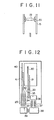
- long and short slender cylindircal tubes 30 and 31 closed at their upper ends and open at their lower ends are located in such a manner that respective upper portions thereof are enclosed in a furnace chamber or a treating chamber, while the lower ends are positioned outside the treating chamber.
- Measuring terminals 32 and 33 of a radiation thermometer are mounted at the open lower ends of the tubes 30 and 31 so that a focal point may be formed at the close upper ends of the tubes 30 and 31.
- Detection signals from the measuring terminals 32 and 33 are fed through optical signal cables 34 and 35 to a photoelectric converter 36 in the HIP unit, therebey taking out an output corresponding to the temperature through lead wires 37 passing through a high pressure vessel.
- the output is supplied to a treating chamber temperature automatic control device 38 and a thyristor control device 39 to control upper and lower heaters 40 and 41.
- This unit is disclosed in Japanese Patent Laid-Open No. 60-144627.
- the place where the optical system is located is usually subjected to a temperature of 300°C under a pressure of 200 atm, and a density of Ar or N 2 gas forming such an atmosphere is higher than that at ordinary temperature and ordinary pressure.
- a density of Ar or N 2 gas forming such an atmosphere is higher than that at ordinary temperature and ordinary pressure.
- an atmosphere around the part has an more increased density.
- a refractive index of the gas increases with an increase in the density, and becomes higher than a value at ordinary temperature and ordinary pressure. Accordingly, optical characteristics of the lens and the optical fiber, which are designed for use in the air under the conditions of ordinary temperature and ordinary pressure, e.g., a focal distance of the lens and a numerical aperture of the optical fiber are changed to cause an influence upon thermometer characteristics.
- the focal distance of the lens is usually expressed in the following equation.
- r 1 and r 2 are radii of curvature of both surfaces of the lens
- n n L /n g
- n Z is an absolute refractive index of the lens
- n g is an absolute refractive index of a medium around the lens.
- n g is substantially equal to 1, and the lens is designed under such conditions.
- the absolute refractive index of the gas changes with pressure as shown in the following table, and therefore, the focal distance is changed according to the above-mentioned equation.
- High-Pressure Testing Techniques and Their Applications, pp. 441 Although the density tends to decrease naturally because of high temperature as well as high pressure in the HIP unit, and a change rate of the refractive index is less than that shown in Table, the condition of the temperature measuring optical system is yet changed.
- the conventional temperature measuring means does not satisfactorily follow the change in the refractive index of the medium gas due to operational conditions of the HIP unit, and cannot attain stable measurement of temperature.
- thermal radiation from a side wall of the closed-end tube 15 having a temperature distribution is also allowed to enter the optical fiber because of a wide angle of visible field of the optical fiber, and such thermal radiation is added to the thermal radiation from the end portion of the closed-end tube, thereby causing an error of temperature measurement at the end portion.
- a limited short wavelength is to be considered from limitation of optical materials, and it has been found that detection of the radiation beam is difficult by the wavelength of 0.2 / um or less and that the wavelength equal to or more than 0.3 / um is preferable.
- the temperature measurement by the radiation thermometer is actually conducted with the wavelength range of 0.3 - 0.6 / um, while it is conducted within the range of 0.3 / um or more in the case of limiting a field of observation at a measurement objective point by means of a collimator or the like.
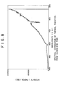
- FIG. 8 An actual spectrum of the radiation beam from the HIP unit is shown in Fig. 8, wherein a clear absorption is observed.
- This absorption is caused by vaporization of a low b.p. metal from a treatment material in the furnace or a capsule glass in the HIP unit. That is, the low b.p. metal in the high-temperature closed vessel of the HIP unit is vaporized during an increase in temperature to generate a gas, which stays in the vessel without being discharged therefrom.
- the metal gas existing in a light path between the objective point and the collimator in conducting a radiation temperature measurement.
- the conventional temperature measuring method does not consider such absorption by the metal gas, and there is a possibility that the absorption by the metal gas is overlapped on the wavelength to be used for the temperature measurement to cause a large error.
- a method of measuring a furnace temperature in a hot isostatic pressing unit comprising the steps of condensing a thermal radiation beam from an end portion of a closed-end tube in a high-pressure furnace of the hot isostatic pressing unit by means of an optical system, feeding the radiation beam from the optical system to a detector to measure the temperature in the furnace, wherein the optical system comprises a solid lens having an incoming surface formed by a spherical surface with center at a temperature measurement objective point and having an outgoing surface formed by a spherical surface with center at a light collecting point, so as to condense a radiant energy from the temperature measurement objective point.
- the optical system for temperature measurement usually corresponds to a collimator system.
- the temperature measurement objective poit corresponds to the end portion of the closed-end tube, and the light collecting point corresponds to an aperture of a photo detecting member such as an optical fiber or a photodetector itself.
- the detector is constituted of a photoelectric converter, amplifier, radiation rate correction circuit and linearizer, etc., and it is designed to carry out indication of temperature.
- the solid lens of the optical system has concave incoming and outgoing surfaces. If the solid lends is formed of a uniform material, a light condensing function cannto be obtained.
- a convex lens member having a high refractive index is incorporated in the solid lens to form the solid lens into a convex lens as a whole, thereby exhibiting the light condensing function.
- the solid lens having the light condensing function may be easily obtained by combining plural lenses, e.g. three lenses having different refraction indexes, or by using a lens having a distribution of refractive index therein.
- the radiation beam from the temperature measurement objective point enters the lens at right angles to the incoming surface, and leaves the lens at right angles to the outgoing surface. That is, no refraction occurs on the incoming surface and the outgoing surface of the lens. Therefore, even when the refractive index of the medium around the lens is changed with fluctuations of temperature and pressure, the radiation beam is not influenced by the change in the refractive index of the medium, thereby ensuring stable temperature measurement.
- a method of measuring a furnace temperature in a hot isostatic pressing unit comprising the steps of condensing a thermal radiation beam from an end portion of a closed-end tube in a high-pressure furnace of the hot isostatic pressing unit by means of an optical system, removing a wavelength of absorption by a low b.p. metal gas vaporized from a treatment material in the furnace or a capsule glass, and feeding the radiation beam from the optical system to a signal processing device to measure the temperature in the furnace.
- the wavelength of radiation beam to be measured is, of course, in the range of 0.3 - 0.6/um as mentioned above, while it is not less than 0.3 / um in the case that the collimator is used to limit a field ob observation to the temperature measurement objective point. Removal of the wavelength of absorption by the low p.b. metal gas may be easily attained by using a filter permitting transmission of a wavelength range except the absortion wavelength of the low p.b. metal.
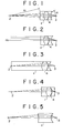
- Figs. 1 to 5 show some examples of the optical system forming the essential part of the present invention, wherein a body of the HIP unit is not illustrated, but the optical systems shown are adapted to the collimator system of the known HIP unit shown in Fig. 9.
- reference numerals 1, 2 and 3 designate a lens, a temperature measurement objective point, and a light collecting point, respectively.
- the incoming surface of the lens 1 is formed by a spherical surface having a radius r 1 with center at the temperature measurement objective point 2, while the outgoing surface is formed by a spherical surface having a radius r 2 with center at the light collecting point 3.
- the incoming surface and the outgoing surface are concave. If the lens 1 were formed of a uniform material, a light condensing function would not be obtained. Accordingly, a convex lens portion 4 having a high refractive index is provided in the lens 1 to form a convex lens as a whole, thus exhibiting the ligth condensing function.
- the lens 1 may be prepared by combining three lenses having different refractive indexes, for example. In this case, it is necessary to sufficiently contact each surface of the lenses to be combined to such an extent that a medium existing in a gap between the lenses influences ignorably upon refraction of the beam.
- the lenses to be combinded may be formed by a plurality of lenses, provided that the incoming and outgoing surfaces of the lens 1 meet the afore-mentioned requirements to function as a convex lens as a whole.
- Fig. 2 shows an example where the temperature measurement objective point 2 is positioned at infinity
- Fig. 3 shows an example where the temperature measurement objective point 2 is positioned in contact with the incoming surface of the lens 1.
- the incoming surface is a substantially flat plane
- Fig. 4 shows an example where the light collecting point 3 is positioned in contact with the outgoing surface of the lens 1, and the outgoing surface is a substantially flat plane.
- a refractive index distributed lens having a function of a convex lens may be used as shown in Fig. 5.
- the refractive index distributed lens is formed by a single lens having a refractive index distribution such that a refractive index is gradually decreased from an optical axial portion of the lens to a peripheral portion.
- the incoming surface and the outgoing surface meet the afore-mentioned requirements like the embodiment of Fig. 1.
- the optical system is formed by the lens system as mentioned above.
- a raiant energy collected by the optical system is transmitted through an optical fiber or the like to a detector, and is then applied to indication of temperature or heater control as required.
- the optical system includes a condensing system l' such as a collimator, a filter 2', a photo-decting unit 3' and a signal processing unit 4 1.
- a radiation beam from an end portion of a closed-end tube (not shown) is condensed by the optical system 1'.
- the filter 2' functions to remove an absoprtion wavelength of a low b.p. metal and select a wavelength range other than the absoprtion wavelength.
- the radiation beam having the wavelength range is transmitted through an optical fiber (not shown) to the signal processing unit 4'v
- the signal processing unit 4' functions to conduct photoelectric conversion to generate a temperature output for indication of temperature or heater control as required.
- the absorption wavelength of the low b.p. metal to be removed is determined as follows:
- a temperature measuring system is not particularly limited, but may includes any means capable of removing the absorption wavelength of the low b.p. metal.
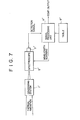
- Fig. 7 shows an alternate embodiment using a spectro thermometer.
- a table 6' stores a data corresponding to an absoprtion wavelength of the low b.p. metal.
- the signal processing unit receives a detection signal from a spectroscope 5', and removes the data corresponding to the .absorption wavelength stores in the table 6' from the detection signal. In this case, wavelength scanning may be cancelled.
Landscapes
- Physics & Mathematics (AREA)
- Spectroscopy & Molecular Physics (AREA)
- General Physics & Mathematics (AREA)
- Engineering & Computer Science (AREA)
- Mechanical Engineering (AREA)
- General Engineering & Computer Science (AREA)
- Radiation Pyrometers (AREA)
Applications Claiming Priority (4)
| Application Number | Priority Date | Filing Date | Title |
|---|---|---|---|
| JP5551/86 | 1986-01-14 | ||
| JP61005551A JPS62163935A (ja) | 1986-01-14 | 1986-01-14 | 熱間静水圧加圧装置の炉内温度測定方法 |
| JP555286A JPS62163936A (ja) | 1986-01-14 | 1986-01-14 | 熱間静水圧加圧装置の炉内温度の測定方法 |
| JP5552/86 | 1986-01-14 |
Publications (3)
| Publication Number | Publication Date |
|---|---|
| EP0229653A2 true EP0229653A2 (fr) | 1987-07-22 |
| EP0229653A3 EP0229653A3 (en) | 1989-03-29 |
| EP0229653B1 EP0229653B1 (fr) | 1992-11-11 |
Family
ID=26339519
Family Applications (1)
| Application Number | Title | Priority Date | Filing Date |
|---|---|---|---|
| EP87100299A Expired - Lifetime EP0229653B1 (fr) | 1986-01-14 | 1987-01-13 | Méthode et dispositif pour mesurer la température d'un four dans une unité de compression isostatique à chaud |
Country Status (3)
| Country | Link |
|---|---|
| US (1) | US4815098A (fr) |
| EP (1) | EP0229653B1 (fr) |
| DE (1) | DE3782505T2 (fr) |
Families Citing this family (4)
| Publication number | Priority date | Publication date | Assignee | Title |
|---|---|---|---|---|
| GB2232244B (en) * | 1989-05-30 | 1992-11-18 | Deutsche Forsch Luft Raumfahrt | A device for measuring the temperature of a body in a vacuum |
| WO2001071410A2 (fr) * | 2000-03-17 | 2001-09-27 | Zograph, Llc | Systeme de lentilles pour acuite elevee |
| US7558452B2 (en) * | 2001-08-02 | 2009-07-07 | Edward Ho | Apparatus and method for collecting energy |
| US7589818B2 (en) * | 2003-12-23 | 2009-09-15 | Asml Netherlands B.V. | Lithographic apparatus, alignment apparatus, device manufacturing method, and a method of converting an apparatus |
Citations (7)
| Publication number | Priority date | Publication date | Assignee | Title |
|---|---|---|---|---|
| JPS54155849A (en) * | 1978-05-30 | 1979-12-08 | Nippon Telegr & Teleph Corp <Ntt> | Mode filter for optical fibers |
| JPS56144411A (en) * | 1980-04-14 | 1981-11-10 | Mitsubishi Electric Corp | Collimating optical system |
| FR2526961A1 (fr) * | 1982-05-14 | 1983-11-18 | Cilas Alcatel | Dispositif pour connecter un generateur de rayonnement optique et un guide d'onde optique |
| JPS5917518A (ja) * | 1982-07-21 | 1984-01-28 | Mitsubishi Electric Corp | 光結合デバイス |
| DE3447724A1 (de) * | 1983-12-22 | 1985-07-04 | Kabushiki Kaisha Kobe Seiko Sho, Kobe | Verfahren zur temperaturmessung in einem hochdruckofen einer isostatischen warmpresse |
| DE3413749A1 (de) * | 1984-04-12 | 1985-10-17 | Telefunken electronic GmbH, 7100 Heilbronn | Optisches system |
| EP0176024A2 (fr) * | 1984-09-19 | 1986-04-02 | Siemens Aktiengesellschaft | Système de lentilles pour la focalisation d'un faisceau laser divergent |
Family Cites Families (14)
| Publication number | Priority date | Publication date | Assignee | Title |
|---|---|---|---|---|
| US30804A (en) * | 1860-12-04 | Feathering paddle-wheel | ||
| JPS4430350Y1 (fr) * | 1966-08-05 | 1969-12-15 | ||
| US3477291A (en) * | 1966-09-05 | 1969-11-11 | Tokyo Shibaura Electric Co | Radiation thermometers |
| US3586419A (en) * | 1968-01-24 | 1971-06-22 | Nippon Kogaku Kk | Optical system having an image distance independent of the refractive index of the medium of object space |
| US3626194A (en) * | 1968-08-30 | 1971-12-07 | Nippon Selfoc Co Ltd | Photoelectric converter including convergent lens with refractive index distribution |
| US3626930A (en) * | 1969-12-15 | 1971-12-14 | Irwing N Toftness | Lens radiation collecting and sensing device |
| US3626758A (en) * | 1969-12-15 | 1971-12-14 | Caterpillar Tractor Co | Remote radiation temperature sensor |
| US3759102A (en) * | 1971-03-25 | 1973-09-18 | Steel Corp | Apparatus for determining correct pyrometer readings with steam interference present |
| US3718383A (en) * | 1971-04-19 | 1973-02-27 | Eastman Kodak Co | Plastic optical element having refractive index gradient |
| DE2317023B2 (de) * | 1973-04-05 | 1980-08-07 | Bodenseewerk Geraetetechnik Gmbh, 7770 Ueberlingen | Schaltungsanordnung zur Linearisierung des Zusammenhangs zwischen dem Ausgangssignal eines Meßgebers und einer MeBgröße |
| USRE30804E (en) | 1978-08-23 | 1981-11-24 | Optical air lens system | |
| JPS6058412B2 (ja) * | 1980-03-19 | 1985-12-19 | 株式会社チノ− | 放射温度計 |
| US4525080A (en) * | 1983-02-08 | 1985-06-25 | The United States Of America As Represented By The Department Of Energy | Apparatus for accurately measuring high temperatures |
| JPS59195611A (ja) * | 1983-04-21 | 1984-11-06 | Mitsubishi Electric Corp | レンズ系 |
-
1987
- 1987-01-13 DE DE8787100299T patent/DE3782505T2/de not_active Expired - Fee Related
- 1987-01-13 EP EP87100299A patent/EP0229653B1/fr not_active Expired - Lifetime
- 1987-01-14 US US07/003,143 patent/US4815098A/en not_active Expired - Lifetime
Patent Citations (7)
| Publication number | Priority date | Publication date | Assignee | Title |
|---|---|---|---|---|
| JPS54155849A (en) * | 1978-05-30 | 1979-12-08 | Nippon Telegr & Teleph Corp <Ntt> | Mode filter for optical fibers |
| JPS56144411A (en) * | 1980-04-14 | 1981-11-10 | Mitsubishi Electric Corp | Collimating optical system |
| FR2526961A1 (fr) * | 1982-05-14 | 1983-11-18 | Cilas Alcatel | Dispositif pour connecter un generateur de rayonnement optique et un guide d'onde optique |
| JPS5917518A (ja) * | 1982-07-21 | 1984-01-28 | Mitsubishi Electric Corp | 光結合デバイス |
| DE3447724A1 (de) * | 1983-12-22 | 1985-07-04 | Kabushiki Kaisha Kobe Seiko Sho, Kobe | Verfahren zur temperaturmessung in einem hochdruckofen einer isostatischen warmpresse |
| DE3413749A1 (de) * | 1984-04-12 | 1985-10-17 | Telefunken electronic GmbH, 7100 Heilbronn | Optisches system |
| EP0176024A2 (fr) * | 1984-09-19 | 1986-04-02 | Siemens Aktiengesellschaft | Système de lentilles pour la focalisation d'un faisceau laser divergent |
Non-Patent Citations (3)
| Title |
|---|
| PATENT ABSTRACTS OF JAPAN, vol. 4, no. 15 (E-170) 5 February 1980, page 45 E 170; & JP-A-54 155 849 (NIPPON DENSHIN DENWA KOSHA) 12-08-1979 * |
| PATENT ABSTRACTS OF JAPAN, vol. 6, no. 22 (P-101)(900) 9 February 1982; & JP-A-56 144 411 (MITSUBISHI DENKI K.K.) 10-11-1981 * |
| PATENT ABSTRACTS OF JAPAN, vol. 8, no. 109 (P-275)(1546) 22 May 1984; & JP-A-59 017 518 (MITSUBISHI DENKI K.K.) 28-01-1984 * |
Also Published As
| Publication number | Publication date |
|---|---|
| DE3782505T2 (de) | 1993-03-25 |
| US4815098A (en) | 1989-03-21 |
| EP0229653B1 (fr) | 1992-11-11 |
| DE3782505D1 (de) | 1992-12-17 |
| EP0229653A3 (en) | 1989-03-29 |
Similar Documents
| Publication | Publication Date | Title |
|---|---|---|
| US5310260A (en) | Non-contact optical techniques for measuring surface conditions | |
| US5387309A (en) | Process for the measurement of the thickness and refractive index of a thin film on a substrate, and an apparatus for carrying out the process | |
| US4576486A (en) | Optical fiber thermometer | |
| US5769540A (en) | Non-contact optical techniques for measuring surface conditions | |
| US4790669A (en) | Spectroscopic method and apparatus for optically measuring temperature | |
| US4679934A (en) | Fiber optic pyrometry with large dynamic range | |
| US4616137A (en) | Optical emission line monitor with background observation and cancellation | |
| WO2000005570A1 (fr) | Systeme capteur a fibres optiques de temperature et de concentration d'hydrogene gazeux | |
| EP0587881A4 (fr) | Photometre ameliore. | |
| EP0425229A1 (fr) | Sonde pyrométrique à haute température | |
| EP0229653A2 (fr) | Méthode et dispositif pour mesurer la température d'un four dans une unité de compression isostatique à chaud | |
| US4666314A (en) | Method and apparatus for measuring temperature in the high pressure furnace of a hot isostatic pressing | |
| Hernberg et al. | Simultaneous in situ measurement of temperature and size of burning char particles in a fluidized bed furnace by means of fiberoptic pyrometry | |
| EP0685720A1 (fr) | Surveillance de température | |
| CN110044495B (zh) | 基于多光谱的温度测量系统及温度测量方法 | |
| US4815841A (en) | High resolution color band pyrometer ratioing | |
| US4605314A (en) | Spectral discrimination pyrometer | |
| Boboridis et al. | A High‐Speed Four‐Channel Infrared Pyrometer | |
| Claggett et al. | Radiation and infrared pyrometers | |
| US3483378A (en) | Apparatus for determining the emittance of a body | |
| JPS60133326A (ja) | 熱間静水圧加圧装置における被処理体の温度測定方法 | |
| Daneman | Fiber-Optic Thermometers | |
| Tong et al. | Performance improvement of radiation-based high-temperature fiber-optic sensor by means of curved sapphire fiber | |
| Farries | Spontaneous Raman temperature sensor | |
| Barron | Application design features for non-contact temperature measurement |
Legal Events
| Date | Code | Title | Description |
|---|---|---|---|
| PUAI | Public reference made under article 153(3) epc to a published international application that has entered the european phase |
Free format text: ORIGINAL CODE: 0009012 |
|
| AK | Designated contracting states |
Kind code of ref document: A2 Designated state(s): DE GB |
|
| PUAL | Search report despatched |
Free format text: ORIGINAL CODE: 0009013 |
|
| AK | Designated contracting states |
Kind code of ref document: A3 Designated state(s): DE GB |
|
| 17P | Request for examination filed |
Effective date: 19890920 |
|
| 17Q | First examination report despatched |
Effective date: 19910925 |
|
| GRAA | (expected) grant |
Free format text: ORIGINAL CODE: 0009210 |
|
| AK | Designated contracting states |
Kind code of ref document: B1 Designated state(s): DE GB |
|
| REF | Corresponds to: |
Ref document number: 3782505 Country of ref document: DE Date of ref document: 19921217 |
|
| PLBE | No opposition filed within time limit |
Free format text: ORIGINAL CODE: 0009261 |
|
| STAA | Information on the status of an ep patent application or granted ep patent |
Free format text: STATUS: NO OPPOSITION FILED WITHIN TIME LIMIT |
|
| 26N | No opposition filed | ||
| REG | Reference to a national code |
Ref country code: GB Ref legal event code: IF02 |
|
| PGFP | Annual fee paid to national office [announced via postgrant information from national office to epo] |
Ref country code: GB Payment date: 20020116 Year of fee payment: 16 |
|
| PGFP | Annual fee paid to national office [announced via postgrant information from national office to epo] |
Ref country code: DE Payment date: 20020212 Year of fee payment: 16 |
|
| PG25 | Lapsed in a contracting state [announced via postgrant information from national office to epo] |
Ref country code: GB Free format text: LAPSE BECAUSE OF NON-PAYMENT OF DUE FEES Effective date: 20030113 |
|
| PG25 | Lapsed in a contracting state [announced via postgrant information from national office to epo] |
Ref country code: DE Free format text: LAPSE BECAUSE OF NON-PAYMENT OF DUE FEES Effective date: 20030801 |
|
| GBPC | Gb: european patent ceased through non-payment of renewal fee |