EP0229212A1 - Nail - Google Patents
Nail Download PDFInfo
- Publication number
- EP0229212A1 EP0229212A1 EP86100520A EP86100520A EP0229212A1 EP 0229212 A1 EP0229212 A1 EP 0229212A1 EP 86100520 A EP86100520 A EP 86100520A EP 86100520 A EP86100520 A EP 86100520A EP 0229212 A1 EP0229212 A1 EP 0229212A1
- Authority
- EP
- European Patent Office
- Prior art keywords
- leg
- nail
- wedge
- wedge guide
- leg sections
- Prior art date
- Legal status (The legal status is an assumption and is not a legal conclusion. Google has not performed a legal analysis and makes no representation as to the accuracy of the status listed.)
- Granted
Links
- 239000011381 foam concrete Substances 0.000 abstract description 18
- 239000000463 material Substances 0.000 abstract description 6
- 239000011810 insulating material Substances 0.000 description 2
- 229920003002 synthetic resin Polymers 0.000 description 2
- 239000000057 synthetic resin Substances 0.000 description 2
- 238000005452 bending Methods 0.000 description 1
- 239000004567 concrete Substances 0.000 description 1
- 239000002184 metal Substances 0.000 description 1
- 238000012545 processing Methods 0.000 description 1
Images
Classifications
-
- F—MECHANICAL ENGINEERING; LIGHTING; HEATING; WEAPONS; BLASTING
- F16—ENGINEERING ELEMENTS AND UNITS; GENERAL MEASURES FOR PRODUCING AND MAINTAINING EFFECTIVE FUNCTIONING OF MACHINES OR INSTALLATIONS; THERMAL INSULATION IN GENERAL
- F16B—DEVICES FOR FASTENING OR SECURING CONSTRUCTIONAL ELEMENTS OR MACHINE PARTS TOGETHER, e.g. NAILS, BOLTS, CIRCLIPS, CLAMPS, CLIPS OR WEDGES; JOINTS OR JOINTING
- F16B15/00—Nails; Staples
- F16B15/04—Nails; Staples with spreading shaft
Definitions
- the present invention relates to a nail, particularly to a nail of a leg-open type used to secure an object to foamed (or autoclaved lightweight) concrete, heat-insulating material, etc.
- FIGs. 6 and 7 show examples of conventional fastener used with foamed concrete, heat-insulating material and similar materials (hereinafter referred to as foamed concrete).
- Fig. 6 shows a tapered nail 11 having four tapering sides. When driven into the material, it compresses foamed concrete with their tapering sides. This increases the frictional resistance between the nail and the foamed concrete and provides a resistance to getting-off or removal. This conventional nail loosens and gets off easily when subjected to vibration, because it resorts merely to the frictional resistance between the nail and the foamed concrete to maintain the resistance to removal.
- Fig. 7 shows an anchor 13 made of synthetic resin and adapted to be driven into a hole formed in the foamed concrete.
- the anchor is formed with a hole 14 to receive a nail.
- a hole has to be formed beforehand in the foamed concrete. This is very inconvenient and requires a special tool for forming the hole.
- An object of the present invention is to provide a nail which provides a sufficient strength to resist the pulling force merely by driving it into the material.
- a nail comprising a nail body and a leg opening member, the nail body having a head and a leg integral with the head, the leg being divided into a plurality of leg sections spaced by a slit extending axially therebetween, the leg sections having their ends tapered at their tip and being coupled together by a breakable portion provided at a distance from the tip of the leg sections, the leg opening member having a wedge guide having such a thickness as to be received in the slit, a washer in the form of a ring formed at one end of the wedge guide and a wedge formed at the other end of the wedge guide and having a pair of tapered surfaces of such a shape as to be received between the tapered ends of the leg sections, the washer being adapted to be put on the leg of the nail hody, the breakable portion having such a strength as to be broken by the upper edge of the wedge guide when the nail is further driven even after the upper edge of the wedge guide has butted the breakable portion.
- the nail according to the present invention comprises a nail body 21, and a leg-opener 31 adapted to be put on the tip of the nail body 21.
- the nail body 21 has a head 23 and a leg 22 divided into a pair of leg sections 25 by a slit 24 extending axially from the tip of the nail to the head 23.
- Each leg section 25 has a tapered surface 26 facing inwardly at its tip.
- the leg sections 25 are coupled together by a plurality of breakable portions 27 in the form of thin rods disposed in the slit 24.
- the leg opener 31 has a wedge guide 32 in the form of a plate having such a thickness as to be received in the slit 24 and a width substantially equal to the diameter of the leg 22, a ring-shaped washer 34 formed at one end of the wedge guide 32, and a wedge 33 formed at the other end thereof.
- the leg opener 31 is formed as an integral unit.
- the wedge 33 has a pair of tapered surfaces so as to be snugly received between the tapered surfaces 26 on the leg sections 25, as shown in Fig. 2, when the leg opener 31 is put on the tip of the nail body 21.
- each of the leg sections 25 is formed with a projection 28 extending axially and the wedge 33 of the leg opener 31 is formed with a pair of grooves 35 extending axially to receive the projections 28 on the leg sections 25. This facilitates positioning of the leg opener 31 with respect to the nail body 21 and serves to guide the axial movement of the former relative to the latter.
- the breakable portions 27 on the nail body 21 serve to position the leg opener 31 with respect to the nail body 21 and to connect the leg sections 25 together, thus preventing the leg portions from bending or getting apart from each other during various processings.
- the breakable portions 27 are formed to have such a strength as to bear the pressure transmitted from the foamed concrete through the wedge guide 32 during an initial stage of nail driving and to be broken by the upper edge of the wedge guide 32 when the nail is driven further after the washer 34 has butted against a part 42 to be secured, as shown in Figs. 2 and 4.
- three breakable portions 27 are provided, but there is no intention of limiting the number of the portions to three.
- the upper edge of the wedge guide 32 is formed with a V-shaped recess 36 to contain the broken pieces of the breakable portions 27.
- the portions 27 may be either integrally formed with the leg portions 25 or formed as separate members of metal or synthetic resin inserted into transverse holes formed in the leg sections 25.
- the leg opener 31 is set on the nail body 21 by inserting the leg sections 25 into the hole in the washer 34 with the wedge guide 32 in the slit 24 of the nail body 21 until the upper edge of the wedge guide 32 butts the lowermost breakable rod 27.
- the leg 22 of the nail body 21 with the leg opener 31 is driven into foamed concrete 41 through a hole 43 formed in the object 42 to be secured.
- the breakable portions 27 will be broken one after another by the wedge guide 32.
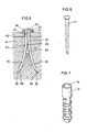
- the leg sections 25 will be forced to open by the wedge 33 of the leg opener 31 as shown in Fig. 5, because the leg opener cannot move further.
- the tapered surfaces on the wedge 33 serve as a guide for guiding the leg sections 25 in opposite directions.
- FIG. 5 shows a final state in which the nail is completely driven with its head 23 on the washer 34. Now, the object 42 is firmly secured to the foamed concrete.
Landscapes
- Engineering & Computer Science (AREA)
- General Engineering & Computer Science (AREA)
- Mechanical Engineering (AREA)
- Joining Of Building Structures In Genera (AREA)
- Portable Nailing Machines And Staplers (AREA)
- Acyclic And Carbocyclic Compounds In Medicinal Compositions (AREA)
- Medicinal Preparation (AREA)
Abstract
Description
- The present invention relates to a nail, particularly to a nail of a leg-open type used to secure an object to foamed (or autoclaved lightweight) concrete, heat-insulating material, etc.
- Since such materials do not have restoring elasticity, a special fastener is needed to secure an object to such a material. Figs. 6 and 7 show examples of conventional fastener used with foamed concrete, heat-insulating material and similar materials (hereinafter referred to as foamed concrete).
- Fig. 6 shows a
tapered nail 11 having four tapering sides. When driven into the material, it compresses foamed concrete with their tapering sides. This increases the frictional resistance between the nail and the foamed concrete and provides a resistance to getting-off or removal. This conventional nail loosens and gets off easily when subjected to vibration, because it resorts merely to the frictional resistance between the nail and the foamed concrete to maintain the resistance to removal. - Fig. 7 shows an
anchor 13 made of synthetic resin and adapted to be driven into a hole formed in the foamed concrete. The anchor is formed with ahole 14 to receive a nail. For use of this anchor, a hole has to be formed beforehand in the foamed concrete. This is very inconvenient and requires a special tool for forming the hole. - An object of the present invention is to provide a nail which provides a sufficient strength to resist the pulling force merely by driving it into the material.
- In accordance with the present invention, there is provided a nail comprising a nail body and a leg opening member, the nail body having a head and a leg integral with the head, the leg being divided into a plurality of leg sections spaced by a slit extending axially therebetween, the leg sections having their ends tapered at their tip and being coupled together by a breakable portion provided at a distance from the tip of the leg sections, the leg opening member having a wedge guide having such a thickness as to be received in the slit, a washer in the form of a ring formed at one end of the wedge guide and a wedge formed at the other end of the wedge guide and having a pair of tapered surfaces of such a shape as to be received between the tapered ends of the leg sections, the washer being adapted to be put on the leg of the nail hody, the breakable portion having such a strength as to be broken by the upper edge of the wedge guide when the nail is further driven even after the upper edge of the wedge guide has butted the breakable portion.
- Other objects and features of the present invention will become apparent from the following description taken with reference to the accompanying drawings, in which:
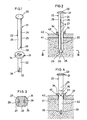
- Fig. 1 is an exploded perspective view of the nail embodying the present invention;
- Fig. 2 is a vertical sectional front view of the nail half-driven;
- Fig. 3 is an enlarged horizontal sectional plan view of the nail taken along the line III - III of Fig. 2;
- Fig. 4 is a vertical sectional side view of the nail half-driven;
- Fig. 5 is a vertical sectional front view showing the nail fully driven;
- Fig. 6 is a perspective view of a conventional nail; and
- Fig. 7 is a perspective view of an anchor used in a conventional fastener.
- Referring to Fig. 1, the nail according to the present invention comprises a
nail body 21, and a leg-opener 31 adapted to be put on the tip of thenail body 21. - The
nail body 21 has ahead 23 and aleg 22 divided into a pair ofleg sections 25 by aslit 24 extending axially from the tip of the nail to thehead 23. Eachleg section 25 has atapered surface 26 facing inwardly at its tip. Theleg sections 25 are coupled together by a plurality ofbreakable portions 27 in the form of thin rods disposed in theslit 24. - The
leg opener 31 has awedge guide 32 in the form of a plate having such a thickness as to be received in theslit 24 and a width substantially equal to the diameter of theleg 22, a ring-shaped washer 34 formed at one end of thewedge guide 32, and awedge 33 formed at the other end thereof. Theleg opener 31 is formed as an integral unit. Thewedge 33 has a pair of tapered surfaces so as to be snugly received between thetapered surfaces 26 on theleg sections 25, as shown in Fig. 2, when theleg opener 31 is put on the tip of thenail body 21. - Referring to Fig. 3, each of the
leg sections 25 is formed with aprojection 28 extending axially and thewedge 33 of theleg opener 31 is formed with a pair ofgrooves 35 extending axially to receive theprojections 28 on theleg sections 25. This facilitates positioning of theleg opener 31 with respect to thenail body 21 and serves to guide the axial movement of the former relative to the latter. - The
breakable portions 27 on thenail body 21 serve to position theleg opener 31 with respect to thenail body 21 and to connect theleg sections 25 together, thus preventing the leg portions from bending or getting apart from each other during various processings. - The
breakable portions 27 are formed to have such a strength as to bear the pressure transmitted from the foamed concrete through thewedge guide 32 during an initial stage of nail driving and to be broken by the upper edge of thewedge guide 32 when the nail is driven further after thewasher 34 has butted against apart 42 to be secured, as shown in Figs. 2 and 4. In the preferred embodiment, threebreakable portions 27 are provided, but there is no intention of limiting the number of the portions to three. The upper edge of thewedge guide 32 is formed with a V-shaped recess 36 to contain the broken pieces of thebreakable portions 27. Theportions 27 may be either integrally formed with theleg portions 25 or formed as separate members of metal or synthetic resin inserted into transverse holes formed in theleg sections 25. - In use, firstly, the
leg opener 31 is set on thenail body 21 by inserting theleg sections 25 into the hole in thewasher 34 with thewedge guide 32 in theslit 24 of thenail body 21 until the upper edge of thewedge guide 32 butts the lowermostbreakable rod 27. - In order to secure an
object 42 to foamed concrete, theleg 22 of thenail body 21 with theleg opener 31 is driven intofoamed concrete 41 through ahole 43 formed in theobject 42 to be secured. - At the initial stage of driving, the pressure applied to the
wedge 33 of theleg opener 31 is borne by thebreakable portion 27 through thewedge guide 32. Therefore, theleg sections 25 advance straightly into the foamed concrete without opening until thewasher 34 butts theobject 42 to be secured, as shown in Figs. 2 and 4. - When the driving of the nail is continued even after the
washer 34 has butted theobject 42, thebreakable portions 27 will be broken one after another by thewedge guide 32. As only thenail body 21 goes further into the foamed concrete, theleg sections 25 will be forced to open by thewedge 33 of theleg opener 31 as shown in Fig. 5, because the leg opener cannot move further. In so functioning, the tapered surfaces on thewedge 33 serve as a guide for guiding theleg sections 25 in opposite directions. - While the nail is being driven, the foamed concrete between the leg sections is fully compressed by the
wedge 33 and theleg sections 25. Thewedge 33 and the compressed foamed concrete between theleg sections 25 serve to prevent theleg sections 25 from restoring to their original positions. This assures a high resistance to pulling-off force applied to the nail. Fig. 5 shows a final state in which the nail is completely driven with itshead 23 on thewasher 34. Now, theobject 42 is firmly secured to the foamed concrete.
Claims (4)
Priority Applications (3)
| Application Number | Priority Date | Filing Date | Title |
|---|---|---|---|
| AT86100520T ATE52581T1 (en) | 1986-01-16 | 1986-01-16 | NAIL. |
| DE8686100520T DE3671073D1 (en) | 1986-01-16 | 1986-01-16 | NAIL. |
| EP86100520A EP0229212B1 (en) | 1986-01-16 | 1986-01-16 | Nail |
Applications Claiming Priority (1)
| Application Number | Priority Date | Filing Date | Title |
|---|---|---|---|
| EP86100520A EP0229212B1 (en) | 1986-01-16 | 1986-01-16 | Nail |
Publications (2)
| Publication Number | Publication Date |
|---|---|
| EP0229212A1 true EP0229212A1 (en) | 1987-07-22 |
| EP0229212B1 EP0229212B1 (en) | 1990-05-09 |
Family
ID=8194831
Family Applications (1)
| Application Number | Title | Priority Date | Filing Date |
|---|---|---|---|
| EP86100520A Expired EP0229212B1 (en) | 1986-01-16 | 1986-01-16 | Nail |
Country Status (3)
| Country | Link |
|---|---|
| EP (1) | EP0229212B1 (en) |
| AT (1) | ATE52581T1 (en) |
| DE (1) | DE3671073D1 (en) |
Cited By (1)
| Publication number | Priority date | Publication date | Assignee | Title |
|---|---|---|---|---|
| DE4138955C1 (en) * | 1991-11-27 | 1993-04-29 | Tadeusz 6000 Frankfurt De Tumalski |
Citations (6)
| Publication number | Priority date | Publication date | Assignee | Title |
|---|---|---|---|---|
| DE203046C (en) * | ||||
| AT15475B (en) * | 1902-04-04 | 1904-03-10 | Michael Karner | Securing device on nails, bolts, clips, screws, etc. like |
| DE337195C (en) * | 1921-05-26 | Peter Bjerring | Expansion nail | |
| US1428111A (en) * | 1920-09-16 | 1922-09-05 | Molesworth Frank | Nail for packing cases and the like |
| US1548456A (en) * | 1924-03-24 | 1925-08-04 | Claude G Rolison | Self-clinching anchor nail |
| EP0090780A1 (en) * | 1982-03-24 | 1983-10-05 | Jan Rube | Fixing device |
-
1986
- 1986-01-16 AT AT86100520T patent/ATE52581T1/en not_active IP Right Cessation
- 1986-01-16 EP EP86100520A patent/EP0229212B1/en not_active Expired
- 1986-01-16 DE DE8686100520T patent/DE3671073D1/en not_active Expired - Fee Related
Patent Citations (6)
| Publication number | Priority date | Publication date | Assignee | Title |
|---|---|---|---|---|
| DE203046C (en) * | ||||
| DE337195C (en) * | 1921-05-26 | Peter Bjerring | Expansion nail | |
| AT15475B (en) * | 1902-04-04 | 1904-03-10 | Michael Karner | Securing device on nails, bolts, clips, screws, etc. like |
| US1428111A (en) * | 1920-09-16 | 1922-09-05 | Molesworth Frank | Nail for packing cases and the like |
| US1548456A (en) * | 1924-03-24 | 1925-08-04 | Claude G Rolison | Self-clinching anchor nail |
| EP0090780A1 (en) * | 1982-03-24 | 1983-10-05 | Jan Rube | Fixing device |
Cited By (2)
| Publication number | Priority date | Publication date | Assignee | Title |
|---|---|---|---|---|
| DE4138955C1 (en) * | 1991-11-27 | 1993-04-29 | Tadeusz 6000 Frankfurt De Tumalski | |
| EP0544194A1 (en) * | 1991-11-27 | 1993-06-02 | Tadeusz Tumalski | Method of manufacturing a nail for porous concrete |
Also Published As
| Publication number | Publication date |
|---|---|
| ATE52581T1 (en) | 1990-05-15 |
| DE3671073D1 (en) | 1990-06-13 |
| EP0229212B1 (en) | 1990-05-09 |
Similar Documents
| Publication | Publication Date | Title |
|---|---|---|
| EP1529966B1 (en) | Dowel fastener and joints including same | |
| US4375342A (en) | Two-piece plastic fastener | |
| US5163795A (en) | Front mounted rivet with interlocked drive pin | |
| US4708552A (en) | Expansible mounting assembly | |
| US5846039A (en) | Positive lock rivet | |
| JP3386241B2 (en) | clip | |
| EP0162637B1 (en) | Fastening apparatus for angularly connecting two plates | |
| US5286152A (en) | Rivet fastener with push-in releasable drive pin | |
| GB2126681A (en) | Dowel fastener and joints including same | |
| JPS611217A (en) | Fastener for mortar wall | |
| JPS6056925B2 (en) | plastic fasteners | |
| CA2449377C (en) | Fastener assembly with centering elements for securing ceiling clip | |
| US6749384B1 (en) | Drive rivet | |
| US5069588A (en) | Anchoring device | |
| US5290137A (en) | Pin bushing | |
| EP0229212A1 (en) | Nail | |
| US5411357A (en) | Screw thread locking insert | |
| US4457651A (en) | Nail | |
| US3373649A (en) | Split fastener with locking wedge | |
| GB2129899A (en) | Expansible anchor | |
| JPH0324727Y2 (en) | ||
| JPH0125765Y2 (en) | ||
| EP0664404B1 (en) | Fittings for elements made of wood or woodlike material | |
| JP3424098B2 (en) | Method of manufacturing anchor for concrete | |
| JPH0874328A (en) | Joint bar anchor |
Legal Events
| Date | Code | Title | Description |
|---|---|---|---|
| PUAI | Public reference made under article 153(3) epc to a published international application that has entered the european phase |
Free format text: ORIGINAL CODE: 0009012 |
|
| AK | Designated contracting states |
Kind code of ref document: A1 Designated state(s): AT CH DE FR GB LI NL SE |
|
| 17P | Request for examination filed |
Effective date: 19870814 |
|
| 17Q | First examination report despatched |
Effective date: 19881202 |
|
| GRAA | (expected) grant |
Free format text: ORIGINAL CODE: 0009210 |
|
| AK | Designated contracting states |
Kind code of ref document: B1 Designated state(s): AT CH DE FR GB LI NL SE |
|
| PG25 | Lapsed in a contracting state [announced via postgrant information from national office to epo] |
Ref country code: NL Effective date: 19900509 Ref country code: LI Effective date: 19900509 Ref country code: FR Effective date: 19900509 Ref country code: CH Effective date: 19900509 Ref country code: AT Effective date: 19900509 |
|
| REF | Corresponds to: |
Ref document number: 52581 Country of ref document: AT Date of ref document: 19900515 Kind code of ref document: T |
|
| REF | Corresponds to: |
Ref document number: 3671073 Country of ref document: DE Date of ref document: 19900613 |
|
| REG | Reference to a national code |
Ref country code: CH Ref legal event code: PL |
|
| EN | Fr: translation not filed | ||
| NLV1 | Nl: lapsed or annulled due to failure to fulfill the requirements of art. 29p and 29m of the patents act | ||
| PLBE | No opposition filed within time limit |
Free format text: ORIGINAL CODE: 0009261 |
|
| STAA | Information on the status of an ep patent application or granted ep patent |
Free format text: STATUS: NO OPPOSITION FILED WITHIN TIME LIMIT |
|
| 26N | No opposition filed | ||
| PGFP | Annual fee paid to national office [announced via postgrant information from national office to epo] |
Ref country code: GB Payment date: 19941230 Year of fee payment: 10 |
|
| PGFP | Annual fee paid to national office [announced via postgrant information from national office to epo] |
Ref country code: SE Payment date: 19950120 Year of fee payment: 10 |
|
| EAL | Se: european patent in force in sweden |
Ref document number: 86100520.5 |
|
| PGFP | Annual fee paid to national office [announced via postgrant information from national office to epo] |
Ref country code: DE Payment date: 19950322 Year of fee payment: 10 |
|
| PG25 | Lapsed in a contracting state [announced via postgrant information from national office to epo] |
Ref country code: GB Effective date: 19960116 |
|
| PG25 | Lapsed in a contracting state [announced via postgrant information from national office to epo] |
Ref country code: SE Effective date: 19960117 |
|
| GBPC | Gb: european patent ceased through non-payment of renewal fee |
Effective date: 19960116 |
|
| PG25 | Lapsed in a contracting state [announced via postgrant information from national office to epo] |
Ref country code: DE Effective date: 19961001 |
|
| EUG | Se: european patent has lapsed |
Ref document number: 86100520.5 |