EP0228132A2 - Méthode de fabrication d'un câble optique - Google Patents
Méthode de fabrication d'un câble optique Download PDFInfo
- Publication number
- EP0228132A2 EP0228132A2 EP86202288A EP86202288A EP0228132A2 EP 0228132 A2 EP0228132 A2 EP 0228132A2 EP 86202288 A EP86202288 A EP 86202288A EP 86202288 A EP86202288 A EP 86202288A EP 0228132 A2 EP0228132 A2 EP 0228132A2
- Authority
- EP
- European Patent Office
- Prior art keywords
- strain relief
- relief elements
- hose
- elements
- tubular casing
- Prior art date
- Legal status (The legal status is an assumption and is not a legal conclusion. Google has not performed a legal analysis and makes no representation as to the accuracy of the status listed.)
- Granted
Links
Images
Classifications
-
- B—PERFORMING OPERATIONS; TRANSPORTING
- B29—WORKING OF PLASTICS; WORKING OF SUBSTANCES IN A PLASTIC STATE IN GENERAL
- B29D—PRODUCING PARTICULAR ARTICLES FROM PLASTICS OR FROM SUBSTANCES IN A PLASTIC STATE
- B29D11/00—Producing optical elements, e.g. lenses or prisms
- B29D11/00663—Production of light guides
- B29D11/00711—Production of light guides by shrinking the sleeve or cladding onto the core
-
- G—PHYSICS
- G02—OPTICS
- G02B—OPTICAL ELEMENTS, SYSTEMS OR APPARATUS
- G02B6/00—Light guides; Structural details of arrangements comprising light guides and other optical elements, e.g. couplings
- G02B6/44—Mechanical structures for providing tensile strength and external protection for fibres, e.g. optical transmission cables
- G02B6/4479—Manufacturing methods of optical cables
- G02B6/4484—Manufacturing methods of optical cables with desired surplus length between fibres and protection features
Definitions
- the invention relates to a method for producing an optical cable, which contains at least one hose element with an extruded hose cover reinforced by strain relief elements, in which at least one fiber optic cable is inserted and guided by excess length by shrinking the hose cover.
- a first casing is first applied to fiber optically guided.
- a second shell is then extruded together with strain relief elements arranged therein.
- the shrinkage resulting from the cooling of the second casing causes the optical fibers loosely led out in the first casing to buckle and therefore have an excess length compared to the finished two-layer tubular casing.
- the strain relief elements also buckle during the shrinking process. You can only absorb significant tensile forces when they have reached an extended position again when the hose element is elongated. Until then, however, there is already a risk that the fiber optic will be subjected to inadmissible mechanical stress.
- LWL breaks can already occur, especially in subsequent production steps such as reeling or stranding several hose elements into a bundle cable.
- the excess length of the fiber optic cable can be reduced to an unacceptable extent by stretching the tube cover.
- the object of the invention is to avoid breaks in the optical fiber in a method of the type mentioned at the outset and to maintain the excess length of the optical fiber to its original extent.
- the solution is achieved by attaching strain relief elements in a stretched position on the circumference of the hose shell immediately after the shrinking of the tubular casing extruded without strain relief elements prior to further operations which cause bending or tensile stress.
- the strain relief elements are only attached in a stretched position when the optical fibers have already reached their excess length due to the end of the shrinkage of the extruded tubular casing.
- the strain relief elements must be dimensioned in such a way that the tensile and bending loads that occur during further production processes can be absorbed before the fiber optic cables are subjected to impermissible loads.
- the strain relief elements to be provided according to the invention do not need to be dimensioned so strongly that they can also withstand operational mechanical stresses on the optical cable.
- a good flexibility of the tube sheaths filled with fiber-optic cables which facilitates the handling of further manufacturing steps results from the fact that a single strain relief element extending over a small angular range of the circumference of the tube element is used.
- two diagonally opposite one another and each over a small one Angle range of the circumference of the hose element extending strain relief elements are used. In both cases there is a practically unimpeded bending possibility in a certain preferred direction.
- Flat band-shaped strain relief elements can be glued particularly easily to the surface of the tubular casing. There is the advantageous possibility that line-shaped surface areas of the tubular casing are heated to form an adhesive layer.
- cord-shaped strain relief elements can preferably be attached by applying them together with the extrusion of a second sleeve to a first sleeve.
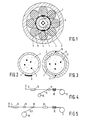
- optical fibers (LWL) 2 are loosely and excessively guided in an extruded plastic sheath.
- the space between the envelope 1 and the fiber optic cables is filled with a gel-like mass 3.
- the casing 1 is wrapped with a swelling fleece 4.
- Strong strain relief elements 6 are arranged between the outer jacket 5 and the swellable nonwoven winding 4, which are intended to absorb the tensile forces acting operationally on the cable.
- relatively weak strain relief elements 7 and 8 are provided, which are pressed into melted narrow areas of the outer surface of the casing 1. These weak strain relief elements 7 and 8 make only a minor contribution to increasing the tensile strength of the finished cable. They only serve to protect the optical fiber from the loads occurring during manufacture during further processing of the tube element consisting of sleeve 1 and optical fiber 2.
- the hose element shown in FIG. 1 can easily be bent around a vertical axis lying in the plane of the paper.
- FIGS. 2 and 3 Alternative embodiments of hose elements are shown in FIGS. 2 and 3.
- cord-shaped strain relief elements 10 and 11 were attached to the casing 1 by extruding the second plastic casing 12. Before they are attached, the first casing must have already shrunk and cooled, so that the second casing 10 does not cause shrinkage to shorten the casing 1. It is advisable to choose such strain relief elements 10 and 11, which can also absorb compression forces.
- the hose elements shown in Figures 1 and 2 can be produced. From an extruder (not shown) (arrow 12), the sheath 1 extruded around the optical fiber 2 enters a cooling device 13. There, the sheath 1 shrinks in the longitudinal direction, so that it becomes shorter than the optical fiber 2. Thereafter, the strain relief elements 7 and 8 or 9 pulled off from a supply roll 15 are glued to the surface of the casing 1 in a suitable device 14. Hose elements obtained in this way can also be subjected to those manufacturing processes which exert mechanical loads by pulling or bending such as a caterpillar take-off 16 or a drum 17 for rolling up the hose element without endangering the optical fiber.
- hose elements of the type shown in FIG. 3 can be produced.
- a drying device 18 is additionally provided, and at location 19 a second extruder, in which 12 strain relief elements 10 and 11 also run in during the extrusion of a second shell.
- the second shell 12 is subsequently cooled in the cooling device 20.
- the hose element thus solidified can then be safely exposed to further mechanically demanding manufacturing processes.
- the excess length of the fiber optic cable originally caused compared to the surrounding tubular casing is retained even when tensile loads occur as a result of further processing.
Applications Claiming Priority (2)
| Application Number | Priority Date | Filing Date | Title |
|---|---|---|---|
| DE3545662 | 1985-12-21 | ||
| DE19853545662 DE3545662A1 (de) | 1985-12-21 | 1985-12-21 | Verfahren zur herstellung eines optischen kabels |
Publications (3)
| Publication Number | Publication Date |
|---|---|
| EP0228132A2 true EP0228132A2 (fr) | 1987-07-08 |
| EP0228132A3 EP0228132A3 (en) | 1989-07-26 |
| EP0228132B1 EP0228132B1 (fr) | 1992-08-05 |
Family
ID=6289303
Family Applications (1)
| Application Number | Title | Priority Date | Filing Date |
|---|---|---|---|
| EP19860202288 Expired - Lifetime EP0228132B1 (fr) | 1985-12-21 | 1986-12-16 | Méthode de fabrication d'un câble optique |
Country Status (2)
| Country | Link |
|---|---|
| EP (1) | EP0228132B1 (fr) |
| DE (2) | DE3545662A1 (fr) |
Cited By (3)
| Publication number | Priority date | Publication date | Assignee | Title |
|---|---|---|---|---|
| EP0456899A2 (fr) * | 1990-05-15 | 1991-11-21 | kabelmetal electro GmbH | Câble aérien à fibres optiques grande portée |
| EP0740170A3 (fr) * | 1989-01-30 | 1998-08-19 | Lumenyte International Corporation | Systèmes de guide optique linéaires et méthodes de fabrication |
| US5822485A (en) * | 1997-01-13 | 1998-10-13 | Siecor Corporation | Optical cable containing parallel flexible strength members and method |
Families Citing this family (4)
| Publication number | Priority date | Publication date | Assignee | Title |
|---|---|---|---|---|
| DE3822566A1 (de) * | 1988-07-04 | 1990-01-11 | Rheydt Kabelwerk Ag | Verfahren zur herstellung eines optischen kabels |
| DE9102185U1 (fr) * | 1991-02-25 | 1991-05-16 | Felten & Guilleaume Energietechnik Ag, 5000 Koeln, De | |
| DE4119881C1 (en) * | 1991-06-17 | 1992-10-08 | Ant Nachrichtentechnik Gmbh, 7150 Backnang, De | Fibre=optic cable containing several optical fibres - has sheath including strain-relieving filaments for protecting fibres surrounded by incompressible gel |
| DE29616177U1 (de) * | 1996-09-17 | 1996-11-21 | Alcatel Kabel Ag | Optisches Kabel |
Citations (6)
| Publication number | Priority date | Publication date | Assignee | Title |
|---|---|---|---|---|
| FR2260806A1 (fr) * | 1974-02-13 | 1975-09-05 | Fort Francois | |
| FR2305748A1 (fr) * | 1975-03-25 | 1976-10-22 | Siemens Ag | Conducteur pour cables optiques |
| DE2641166A1 (de) * | 1975-09-19 | 1977-03-31 | Cables De Lyon Geoffroy Delore | Ummantelte lichtleitfaser |
| FR2342508A1 (fr) * | 1976-02-25 | 1977-09-23 | Western Electric Co | Cable de communications optiques |
| US4241979A (en) * | 1979-01-18 | 1980-12-30 | Bell Telephone Laboratories, Incorporated | Optical communication cable with means for controlling coupling between cable jacket and strength members |
| DE3320072A1 (de) * | 1983-06-03 | 1984-12-06 | Siemens AG, 1000 Berlin und 8000 München | Lichtwellenleiterkabel und verfahren zu dessen herstellung |
-
1985
- 1985-12-21 DE DE19853545662 patent/DE3545662A1/de not_active Withdrawn
-
1986
- 1986-12-16 DE DE8686202288T patent/DE3686318D1/de not_active Expired - Lifetime
- 1986-12-16 EP EP19860202288 patent/EP0228132B1/fr not_active Expired - Lifetime
Patent Citations (6)
| Publication number | Priority date | Publication date | Assignee | Title |
|---|---|---|---|---|
| FR2260806A1 (fr) * | 1974-02-13 | 1975-09-05 | Fort Francois | |
| FR2305748A1 (fr) * | 1975-03-25 | 1976-10-22 | Siemens Ag | Conducteur pour cables optiques |
| DE2641166A1 (de) * | 1975-09-19 | 1977-03-31 | Cables De Lyon Geoffroy Delore | Ummantelte lichtleitfaser |
| FR2342508A1 (fr) * | 1976-02-25 | 1977-09-23 | Western Electric Co | Cable de communications optiques |
| US4241979A (en) * | 1979-01-18 | 1980-12-30 | Bell Telephone Laboratories, Incorporated | Optical communication cable with means for controlling coupling between cable jacket and strength members |
| DE3320072A1 (de) * | 1983-06-03 | 1984-12-06 | Siemens AG, 1000 Berlin und 8000 München | Lichtwellenleiterkabel und verfahren zu dessen herstellung |
Cited By (4)
| Publication number | Priority date | Publication date | Assignee | Title |
|---|---|---|---|---|
| EP0740170A3 (fr) * | 1989-01-30 | 1998-08-19 | Lumenyte International Corporation | Systèmes de guide optique linéaires et méthodes de fabrication |
| EP0456899A2 (fr) * | 1990-05-15 | 1991-11-21 | kabelmetal electro GmbH | Câble aérien à fibres optiques grande portée |
| EP0456899A3 (en) * | 1990-05-15 | 1993-05-26 | Kabelmetal Electro Gmbh | Fibre optic overhead cable for long suspension lengths |
| US5822485A (en) * | 1997-01-13 | 1998-10-13 | Siecor Corporation | Optical cable containing parallel flexible strength members and method |
Also Published As
| Publication number | Publication date |
|---|---|
| DE3545662A1 (de) | 1987-06-25 |
| DE3686318D1 (de) | 1992-09-10 |
| EP0228132A3 (en) | 1989-07-26 |
| EP0228132B1 (fr) | 1992-08-05 |
Similar Documents
| Publication | Publication Date | Title |
|---|---|---|
| EP0126509B1 (fr) | Elément de câble ou câble optique et procédé de sa fabrication | |
| DE60037026T2 (de) | Faseroptisches kabel mit verstärkungselement innerhalb einer äusseren umhüllung | |
| DE19717313A1 (de) | Optisches Kabel und Verfahren zum Herstellen eines optischen Kabels | |
| DE2854746A1 (de) | Optisches kabel | |
| DE2641166A1 (de) | Ummantelte lichtleitfaser | |
| EP0548592A1 (fr) | Méthode de fabrication d'un élément d'un câble à fibre optique | |
| DE3118172A1 (de) | Laengswasserdichtes optisches nachrichtenkabel | |
| EP0182030A1 (fr) | Fibre optique sensible aux forces de traction et procédé pour sa fabrication | |
| DE4101082C1 (fr) | ||
| EP0135224A2 (fr) | Procédé de fabrication de câbles et câbles fabriqués selon ce procédé, en particulier câbles optiques | |
| EP0228132B1 (fr) | Méthode de fabrication d'un câble optique | |
| DE3023669C2 (de) | Selbsttragendes optisches Nachrichtenkabel | |
| DE3309996C2 (fr) | ||
| EP0072423A1 (fr) | Câble optique de télécommunication | |
| DE2701650C2 (de) | Ader für ein optisches Kabel bzw. ein optisches Kabelelement | |
| DE2930643A1 (de) | Huelle fuer optische fasern | |
| DE3526823A1 (de) | Element mit mehreren lichtwellenleitern | |
| DE2845887C2 (fr) | ||
| DE19900214A1 (de) | Optisches Kabel | |
| DE2259703C3 (de) | Selbsttragendes Luftkabel | |
| EP0141307B1 (fr) | Câble optique | |
| DE3632849A1 (de) | Optisches kabel | |
| EP0379126B1 (fr) | Câble à fibre optique | |
| DE3808828C2 (fr) | ||
| DE69837304T2 (de) | Ummantelte optische Faser und Herstellungsverfahren |
Legal Events
| Date | Code | Title | Description |
|---|---|---|---|
| PUAI | Public reference made under article 153(3) epc to a published international application that has entered the european phase |
Free format text: ORIGINAL CODE: 0009012 |
|
| AK | Designated contracting states |
Kind code of ref document: A2 Designated state(s): DE FR GB IT NL |
|
| RAP1 | Party data changed (applicant data changed or rights of an application transferred) |
Owner name: N.V. PHILIPS' GLOEILAMPENFABRIEKEN Owner name: PHILIPS PATENTVERWALTUNG GMBH |
|
| PUAL | Search report despatched |
Free format text: ORIGINAL CODE: 0009013 |
|
| AK | Designated contracting states |
Kind code of ref document: A3 Designated state(s): DE FR GB IT NL |
|
| 17P | Request for examination filed |
Effective date: 19900118 |
|
| 17Q | First examination report despatched |
Effective date: 19910723 |
|
| ITTA | It: last paid annual fee | ||
| GRAA | (expected) grant |
Free format text: ORIGINAL CODE: 0009210 |
|
| AK | Designated contracting states |
Kind code of ref document: B1 Designated state(s): DE FR GB IT NL |
|
| PG25 | Lapsed in a contracting state [announced via postgrant information from national office to epo] |
Ref country code: NL Effective date: 19920805 |
|
| REF | Corresponds to: |
Ref document number: 3686318 Country of ref document: DE Date of ref document: 19920910 |
|
| ITF | It: translation for a ep patent filed |
Owner name: ING. C. GREGORJ S.P.A. |
|
| ET | Fr: translation filed | ||
| PGFP | Annual fee paid to national office [announced via postgrant information from national office to epo] |
Ref country code: GB Payment date: 19921201 Year of fee payment: 7 |
|
| GBT | Gb: translation of ep patent filed (gb section 77(6)(a)/1977) | ||
| PGFP | Annual fee paid to national office [announced via postgrant information from national office to epo] |
Ref country code: FR Payment date: 19921222 Year of fee payment: 7 |
|
| NLV1 | Nl: lapsed or annulled due to failure to fulfill the requirements of art. 29p and 29m of the patents act | ||
| PLBE | No opposition filed within time limit |
Free format text: ORIGINAL CODE: 0009261 |
|
| STAA | Information on the status of an ep patent application or granted ep patent |
Free format text: STATUS: NO OPPOSITION FILED WITHIN TIME LIMIT |
|
| 26N | No opposition filed | ||
| PG25 | Lapsed in a contracting state [announced via postgrant information from national office to epo] |
Ref country code: GB Effective date: 19931216 |
|
| GBPC | Gb: european patent ceased through non-payment of renewal fee |
Effective date: 19931216 |
|
| PG25 | Lapsed in a contracting state [announced via postgrant information from national office to epo] |
Ref country code: FR Effective date: 19940831 |
|
| REG | Reference to a national code |
Ref country code: FR Ref legal event code: ST |
|
| PGFP | Annual fee paid to national office [announced via postgrant information from national office to epo] |
Ref country code: DE Payment date: 19971124 Year of fee payment: 12 |
|
| PG25 | Lapsed in a contracting state [announced via postgrant information from national office to epo] |
Ref country code: DE Free format text: LAPSE BECAUSE OF NON-PAYMENT OF DUE FEES Effective date: 19991001 |
|
| PG25 | Lapsed in a contracting state [announced via postgrant information from national office to epo] |
Ref country code: IT Free format text: LAPSE BECAUSE OF NON-PAYMENT OF DUE FEES;WARNING: LAPSES OF ITALIAN PATENTS WITH EFFECTIVE DATE BEFORE 2007 MAY HAVE OCCURRED AT ANY TIME BEFORE 2007. THE CORRECT EFFECTIVE DATE MAY BE DIFFERENT FROM THE ONE RECORDED. Effective date: 20051216 |