EP0227981B1 - Production method of an optical recording medium - Google Patents
Production method of an optical recording medium Download PDFInfo
- Publication number
- EP0227981B1 EP0227981B1 EP19860116999 EP86116999A EP0227981B1 EP 0227981 B1 EP0227981 B1 EP 0227981B1 EP 19860116999 EP19860116999 EP 19860116999 EP 86116999 A EP86116999 A EP 86116999A EP 0227981 B1 EP0227981 B1 EP 0227981B1
- Authority
- EP
- European Patent Office
- Prior art keywords
- layer
- recording
- under layer
- optical recording
- disc
- Prior art date
- Legal status (The legal status is an assumption and is not a legal conclusion. Google has not performed a legal analysis and makes no representation as to the accuracy of the status listed.)
- Expired - Lifetime
Links
Images


Classifications
-
- G—PHYSICS
- G11—INFORMATION STORAGE
- G11B—INFORMATION STORAGE BASED ON RELATIVE MOVEMENT BETWEEN RECORD CARRIER AND TRANSDUCER
- G11B7/00—Recording or reproducing by optical means, e.g. recording using a thermal beam of optical radiation by modifying optical properties or the physical structure, reproducing using an optical beam at lower power by sensing optical properties; Record carriers therefor
- G11B7/24—Record carriers characterised by shape, structure or physical properties, or by the selection of the material
- G11B7/241—Record carriers characterised by shape, structure or physical properties, or by the selection of the material characterised by the selection of the material
-
- G—PHYSICS
- G11—INFORMATION STORAGE
- G11B—INFORMATION STORAGE BASED ON RELATIVE MOVEMENT BETWEEN RECORD CARRIER AND TRANSDUCER
- G11B7/00—Recording or reproducing by optical means, e.g. recording using a thermal beam of optical radiation by modifying optical properties or the physical structure, reproducing using an optical beam at lower power by sensing optical properties; Record carriers therefor
- G11B7/24—Record carriers characterised by shape, structure or physical properties, or by the selection of the material
- G11B7/241—Record carriers characterised by shape, structure or physical properties, or by the selection of the material characterised by the selection of the material
- G11B7/252—Record carriers characterised by shape, structure or physical properties, or by the selection of the material characterised by the selection of the material of layers other than recording layers
- G11B7/257—Record carriers characterised by shape, structure or physical properties, or by the selection of the material characterised by the selection of the material of layers other than recording layers of layers having properties involved in recording or reproduction, e.g. optical interference layers or sensitising layers or dielectric layers, which are protecting the recording layers
- G11B7/2572—Record carriers characterised by shape, structure or physical properties, or by the selection of the material characterised by the selection of the material of layers other than recording layers of layers having properties involved in recording or reproduction, e.g. optical interference layers or sensitising layers or dielectric layers, which are protecting the recording layers consisting essentially of organic materials
- G11B7/2575—Record carriers characterised by shape, structure or physical properties, or by the selection of the material characterised by the selection of the material of layers other than recording layers of layers having properties involved in recording or reproduction, e.g. optical interference layers or sensitising layers or dielectric layers, which are protecting the recording layers consisting essentially of organic materials resins
-
- G—PHYSICS
- G11—INFORMATION STORAGE
- G11B—INFORMATION STORAGE BASED ON RELATIVE MOVEMENT BETWEEN RECORD CARRIER AND TRANSDUCER
- G11B7/00—Recording or reproducing by optical means, e.g. recording using a thermal beam of optical radiation by modifying optical properties or the physical structure, reproducing using an optical beam at lower power by sensing optical properties; Record carriers therefor
- G11B7/24—Record carriers characterised by shape, structure or physical properties, or by the selection of the material
- G11B7/26—Apparatus or processes specially adapted for the manufacture of record carriers
-
- G—PHYSICS
- G11—INFORMATION STORAGE
- G11B—INFORMATION STORAGE BASED ON RELATIVE MOVEMENT BETWEEN RECORD CARRIER AND TRANSDUCER
- G11B7/00—Recording or reproducing by optical means, e.g. recording using a thermal beam of optical radiation by modifying optical properties or the physical structure, reproducing using an optical beam at lower power by sensing optical properties; Record carriers therefor
- G11B7/24—Record carriers characterised by shape, structure or physical properties, or by the selection of the material
- G11B7/241—Record carriers characterised by shape, structure or physical properties, or by the selection of the material characterised by the selection of the material
- G11B7/242—Record carriers characterised by shape, structure or physical properties, or by the selection of the material characterised by the selection of the material of recording layers
- G11B7/243—Record carriers characterised by shape, structure or physical properties, or by the selection of the material characterised by the selection of the material of recording layers comprising inorganic materials only, e.g. ablative layers
- G11B2007/24302—Metals or metalloids
- G11B2007/24312—Metals or metalloids group 14 elements (e.g. Si, Ge, Sn)
-
- G—PHYSICS
- G11—INFORMATION STORAGE
- G11B—INFORMATION STORAGE BASED ON RELATIVE MOVEMENT BETWEEN RECORD CARRIER AND TRANSDUCER
- G11B7/00—Recording or reproducing by optical means, e.g. recording using a thermal beam of optical radiation by modifying optical properties or the physical structure, reproducing using an optical beam at lower power by sensing optical properties; Record carriers therefor
- G11B7/24—Record carriers characterised by shape, structure or physical properties, or by the selection of the material
- G11B7/241—Record carriers characterised by shape, structure or physical properties, or by the selection of the material characterised by the selection of the material
- G11B7/242—Record carriers characterised by shape, structure or physical properties, or by the selection of the material characterised by the selection of the material of recording layers
- G11B7/243—Record carriers characterised by shape, structure or physical properties, or by the selection of the material characterised by the selection of the material of recording layers comprising inorganic materials only, e.g. ablative layers
- G11B2007/24302—Metals or metalloids
- G11B2007/24316—Metals or metalloids group 16 elements (i.e. chalcogenides, Se, Te)
-
- G—PHYSICS
- G11—INFORMATION STORAGE
- G11B—INFORMATION STORAGE BASED ON RELATIVE MOVEMENT BETWEEN RECORD CARRIER AND TRANSDUCER
- G11B7/00—Recording or reproducing by optical means, e.g. recording using a thermal beam of optical radiation by modifying optical properties or the physical structure, reproducing using an optical beam at lower power by sensing optical properties; Record carriers therefor
- G11B7/24—Record carriers characterised by shape, structure or physical properties, or by the selection of the material
- G11B7/241—Record carriers characterised by shape, structure or physical properties, or by the selection of the material characterised by the selection of the material
- G11B7/252—Record carriers characterised by shape, structure or physical properties, or by the selection of the material characterised by the selection of the material of layers other than recording layers
- G11B7/253—Record carriers characterised by shape, structure or physical properties, or by the selection of the material characterised by the selection of the material of layers other than recording layers of substrates
- G11B7/2533—Record carriers characterised by shape, structure or physical properties, or by the selection of the material characterised by the selection of the material of layers other than recording layers of substrates comprising resins
- G11B7/2534—Record carriers characterised by shape, structure or physical properties, or by the selection of the material characterised by the selection of the material of layers other than recording layers of substrates comprising resins polycarbonates [PC]
-
- Y—GENERAL TAGGING OF NEW TECHNOLOGICAL DEVELOPMENTS; GENERAL TAGGING OF CROSS-SECTIONAL TECHNOLOGIES SPANNING OVER SEVERAL SECTIONS OF THE IPC; TECHNICAL SUBJECTS COVERED BY FORMER USPC CROSS-REFERENCE ART COLLECTIONS [XRACs] AND DIGESTS
- Y10—TECHNICAL SUBJECTS COVERED BY FORMER USPC
- Y10S—TECHNICAL SUBJECTS COVERED BY FORMER USPC CROSS-REFERENCE ART COLLECTIONS [XRACs] AND DIGESTS
- Y10S428/00—Stock material or miscellaneous articles
- Y10S428/913—Material designed to be responsive to temperature, light, moisture
-
- Y—GENERAL TAGGING OF NEW TECHNOLOGICAL DEVELOPMENTS; GENERAL TAGGING OF CROSS-SECTIONAL TECHNOLOGIES SPANNING OVER SEVERAL SECTIONS OF THE IPC; TECHNICAL SUBJECTS COVERED BY FORMER USPC CROSS-REFERENCE ART COLLECTIONS [XRACs] AND DIGESTS
- Y10—TECHNICAL SUBJECTS COVERED BY FORMER USPC
- Y10S—TECHNICAL SUBJECTS COVERED BY FORMER USPC CROSS-REFERENCE ART COLLECTIONS [XRACs] AND DIGESTS
- Y10S430/00—Radiation imagery chemistry: process, composition, or product thereof
- Y10S430/146—Laser beam
-
- Y—GENERAL TAGGING OF NEW TECHNOLOGICAL DEVELOPMENTS; GENERAL TAGGING OF CROSS-SECTIONAL TECHNOLOGIES SPANNING OVER SEVERAL SECTIONS OF THE IPC; TECHNICAL SUBJECTS COVERED BY FORMER USPC CROSS-REFERENCE ART COLLECTIONS [XRACs] AND DIGESTS
- Y10—TECHNICAL SUBJECTS COVERED BY FORMER USPC
- Y10T—TECHNICAL SUBJECTS COVERED BY FORMER US CLASSIFICATION
- Y10T428/00—Stock material or miscellaneous articles
- Y10T428/26—Web or sheet containing structurally defined element or component, the element or component having a specified physical dimension
- Y10T428/261—In terms of molecular thickness or light wave length
-
- Y—GENERAL TAGGING OF NEW TECHNOLOGICAL DEVELOPMENTS; GENERAL TAGGING OF CROSS-SECTIONAL TECHNOLOGIES SPANNING OVER SEVERAL SECTIONS OF THE IPC; TECHNICAL SUBJECTS COVERED BY FORMER USPC CROSS-REFERENCE ART COLLECTIONS [XRACs] AND DIGESTS
- Y10—TECHNICAL SUBJECTS COVERED BY FORMER USPC
- Y10T—TECHNICAL SUBJECTS COVERED BY FORMER US CLASSIFICATION
- Y10T428/00—Stock material or miscellaneous articles
- Y10T428/26—Web or sheet containing structurally defined element or component, the element or component having a specified physical dimension
- Y10T428/266—Web or sheet containing structurally defined element or component, the element or component having a specified physical dimension of base or substrate
-
- Y—GENERAL TAGGING OF NEW TECHNOLOGICAL DEVELOPMENTS; GENERAL TAGGING OF CROSS-SECTIONAL TECHNOLOGIES SPANNING OVER SEVERAL SECTIONS OF THE IPC; TECHNICAL SUBJECTS COVERED BY FORMER USPC CROSS-REFERENCE ART COLLECTIONS [XRACs] AND DIGESTS
- Y10—TECHNICAL SUBJECTS COVERED BY FORMER USPC
- Y10T—TECHNICAL SUBJECTS COVERED BY FORMER US CLASSIFICATION
- Y10T428/00—Stock material or miscellaneous articles
- Y10T428/31504—Composite [nonstructural laminate]
- Y10T428/31507—Of polycarbonate
-
- Y—GENERAL TAGGING OF NEW TECHNOLOGICAL DEVELOPMENTS; GENERAL TAGGING OF CROSS-SECTIONAL TECHNOLOGIES SPANNING OVER SEVERAL SECTIONS OF THE IPC; TECHNICAL SUBJECTS COVERED BY FORMER USPC CROSS-REFERENCE ART COLLECTIONS [XRACs] AND DIGESTS
- Y10—TECHNICAL SUBJECTS COVERED BY FORMER USPC
- Y10T—TECHNICAL SUBJECTS COVERED BY FORMER US CLASSIFICATION
- Y10T428/00—Stock material or miscellaneous articles
- Y10T428/31504—Composite [nonstructural laminate]
- Y10T428/31511—Of epoxy ether
-
- Y—GENERAL TAGGING OF NEW TECHNOLOGICAL DEVELOPMENTS; GENERAL TAGGING OF CROSS-SECTIONAL TECHNOLOGIES SPANNING OVER SEVERAL SECTIONS OF THE IPC; TECHNICAL SUBJECTS COVERED BY FORMER USPC CROSS-REFERENCE ART COLLECTIONS [XRACs] AND DIGESTS
- Y10—TECHNICAL SUBJECTS COVERED BY FORMER USPC
- Y10T—TECHNICAL SUBJECTS COVERED BY FORMER US CLASSIFICATION
- Y10T428/00—Stock material or miscellaneous articles
- Y10T428/31504—Composite [nonstructural laminate]
- Y10T428/3154—Of fluorinated addition polymer from unsaturated monomers
- Y10T428/31544—Addition polymer is perhalogenated
-
- Y—GENERAL TAGGING OF NEW TECHNOLOGICAL DEVELOPMENTS; GENERAL TAGGING OF CROSS-SECTIONAL TECHNOLOGIES SPANNING OVER SEVERAL SECTIONS OF THE IPC; TECHNICAL SUBJECTS COVERED BY FORMER USPC CROSS-REFERENCE ART COLLECTIONS [XRACs] AND DIGESTS
- Y10—TECHNICAL SUBJECTS COVERED BY FORMER USPC
- Y10T—TECHNICAL SUBJECTS COVERED BY FORMER US CLASSIFICATION
- Y10T428/00—Stock material or miscellaneous articles
- Y10T428/31504—Composite [nonstructural laminate]
- Y10T428/31678—Of metal
- Y10T428/31681—Next to polyester, polyamide or polyimide [e.g., alkyd, glue, or nylon, etc.]
-
- Y—GENERAL TAGGING OF NEW TECHNOLOGICAL DEVELOPMENTS; GENERAL TAGGING OF CROSS-SECTIONAL TECHNOLOGIES SPANNING OVER SEVERAL SECTIONS OF THE IPC; TECHNICAL SUBJECTS COVERED BY FORMER USPC CROSS-REFERENCE ART COLLECTIONS [XRACs] AND DIGESTS
- Y10—TECHNICAL SUBJECTS COVERED BY FORMER USPC
- Y10T—TECHNICAL SUBJECTS COVERED BY FORMER US CLASSIFICATION
- Y10T428/00—Stock material or miscellaneous articles
- Y10T428/31504—Composite [nonstructural laminate]
- Y10T428/31678—Of metal
- Y10T428/31692—Next to addition polymer from unsaturated monomers
-
- Y—GENERAL TAGGING OF NEW TECHNOLOGICAL DEVELOPMENTS; GENERAL TAGGING OF CROSS-SECTIONAL TECHNOLOGIES SPANNING OVER SEVERAL SECTIONS OF THE IPC; TECHNICAL SUBJECTS COVERED BY FORMER USPC CROSS-REFERENCE ART COLLECTIONS [XRACs] AND DIGESTS
- Y10—TECHNICAL SUBJECTS COVERED BY FORMER USPC
- Y10T—TECHNICAL SUBJECTS COVERED BY FORMER US CLASSIFICATION
- Y10T428/00—Stock material or miscellaneous articles
- Y10T428/31504—Composite [nonstructural laminate]
- Y10T428/31721—Of polyimide
-
- Y—GENERAL TAGGING OF NEW TECHNOLOGICAL DEVELOPMENTS; GENERAL TAGGING OF CROSS-SECTIONAL TECHNOLOGIES SPANNING OVER SEVERAL SECTIONS OF THE IPC; TECHNICAL SUBJECTS COVERED BY FORMER USPC CROSS-REFERENCE ART COLLECTIONS [XRACs] AND DIGESTS
- Y10—TECHNICAL SUBJECTS COVERED BY FORMER USPC
- Y10T—TECHNICAL SUBJECTS COVERED BY FORMER US CLASSIFICATION
- Y10T428/00—Stock material or miscellaneous articles
- Y10T428/31504—Composite [nonstructural laminate]
- Y10T428/31786—Of polyester [e.g., alkyd, etc.]
-
- Y—GENERAL TAGGING OF NEW TECHNOLOGICAL DEVELOPMENTS; GENERAL TAGGING OF CROSS-SECTIONAL TECHNOLOGIES SPANNING OVER SEVERAL SECTIONS OF THE IPC; TECHNICAL SUBJECTS COVERED BY FORMER USPC CROSS-REFERENCE ART COLLECTIONS [XRACs] AND DIGESTS
- Y10—TECHNICAL SUBJECTS COVERED BY FORMER USPC
- Y10T—TECHNICAL SUBJECTS COVERED BY FORMER US CLASSIFICATION
- Y10T428/00—Stock material or miscellaneous articles
- Y10T428/31504—Composite [nonstructural laminate]
- Y10T428/31826—Of natural rubber
- Y10T428/3183—Next to second layer of natural rubber
Definitions
- the present invention relates to a process for the manufacture of an optical recording medium for recording and playing back an information signal by radiating a light beam thereon and a method of the production thereof.
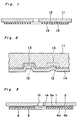
- Fig. 1 shows one example of this sort of a single sided optical recording disc
- Fig. 2 is an enlarged cross sectional view of the center portion thereof.
- pregrooves 12 corresponding to a tracking signal and prepits 13 corresponding to an address signal are transferred onto one surface of a disc substrate 11 of the optical recording medium, and a recording layer 14 made of a recording material for the heat mode is formed on the transferred surface where the pregrooves 12 and the prepits 13 are formed.
- the prepits 13 is formed on the pregrooves 12, and each of the information signals corresponding to the difference between the depths of the prepits 13 and the pregrooves 12 is read out.
- an information signal is recorded in the recording layer 14 of the optical recording disc
- the following process is performed. First of all, a laser beam for tracking is radiated from the side of the disc substrate 11 along the pregrooves 12 and the prepits 13, and the tracking information signal and the address information signal are detected by a receiver in a recording and playback device for detecting the light reflected on the recording layer 14.
- the laser beam modulated by the predetermined information signal is radiated onto the predetermined track and the predetermined sector, so that the thermal deformation such as melting, evaporation, sublimation, and contraction occurs in the recording layer 14, resulting in that pits designating the information signal are formed in the recording layer 14.
- the laser beam is radiated from the side of the disc substrate 11 along the pregrooves 12, the tracking information signal and the address information signal are detected by detecting the light reflected on the recording layer 14, resulting in that the information signal recorded in the recording layer 14 can be detected.
- a high polymeric material such as polymethylmethacrylate (referred to hereinafter as PMMA), polycarbonate (referred to hereinafter as PC), epoxy resin etc. formed by the injection molding method is widely used as the disc substrate 11 provided to this sort of optical recording disc, because the inexpensive high polymeric material can be produced with a high productivity, the material is relatively light and is not easily damaged, and the material can be transferred and dealt easily, etc..
- PMMA polymethylmethacrylate
- PC polycarbonate
- epoxy resin etc. formed by the injection molding method is widely used as the disc substrate 11 provided to this sort of optical recording disc, because the inexpensive high polymeric material can be produced with a high productivity, the material is relatively light and is not easily damaged, and the material can be transferred and dealt easily, etc.
- the high polymeric material has a relatively low heat resistance
- shapes of pregrooves 12 and the prepits 13 transferred onto the disc substrate 11 may be gradually changed after the laser beam for playback is repeatedly radiated onto the recording layer 14, and the problems, that the contrast between the reflected light decreases and the carrier to noise level ratio (referred to hereinafter as the CN ratio) decreases, have been pointed out.
- an information recording medium comprising an adiabatic layer with a transparency between the disc substrate 11 and the recording layer 14 is publicly known (the Japanese patent laid open No.
- the adiabatic layer is made of a transparent material having a high heat resistance that the material cannot be deformed at a higher temperature than the temperature of the recording layer 14 when recording, and having a low heat conductivity and the adiabatic effect, for example, the material is made of CuSe and As2Se3 etc. including one of Se and S at a larger atomic percentage than 40 atomic percentage.
- ultraviolet curing resin the Japanese patent laid open No. 86756/1978
- cellulose nitrate the Japanese patent laid open No. 55544/1982
- the rotating and coating method or the vacuum evaporation method is normally used.
- a thin layer made of Te group is used as the material of the recording layer 14
- an organic compound such as ultraviolet curing resin, cellulose nitrate etc. which can be coated by the rotating and coating method is used as an under layer arranged under the recording layer 14.
- DE-A-29 35 859 describes an optical recording medium which comprises a substrate, a recording layer and an underlayer.
- the optical recording medium is provided with an underlayer between the disc substrate and the recording layer.
- the underlayer is made of a high polymeric material having a lower melting point, a lower decomposition temperature and a lower heat conductivity than the recording layer and the layers are made by vacuum evaporation method.
- the characteristic of the heat resistance of the under layer formed under the recording layer 14 remarkably influences the recording sensitivity of the recording layer 14, and it is found that the thermal deformation of the recording layer 14 is facilitated by the thermal deformation of the under layer which is the disc substrate 11, that is, the recording sensitivity of the recording layer 14 remarkably decreases when the thermal deformation does not occur at all.
- the recording sensitivity remarkably decreases as compared that the case that the recording layer 14 is formed on the disc substrate 11 made of PMMA.
- the thermal deformation of the disc substrate 11 can be prevented and the decrease of the CN ratio can be prevented.
- the recording sensitivity remarkably decreases, and there is a problem that the laser power must be increased.
- the recording sensitivity decreases.
- the recording sensitivity does not decrease, however, it is necessary to perform the troublesome rotating and coating process with a relatively low productivity, and it is difficult to form the under layer made of cellulose nitrate uniformly with a thickness.
- the forming method of recording layer made of Te group is widely used as the sputtering method, therefore, the rotating and coating method is not desirable method.
- An essential object of the present invention is to provide a production method for an optical recording medium with a relatively high productivity, the optical recording medium having a substrate not deformed and having a larger recording sensitivity than the optical recording disc of the prior art, even though a laser beam for playback is repeatedly radiated onto a recording layer.
- the invention is defined in the claims.
- the production method of the optical recording medium comprising a process of forming an under layer on an uneven pattern of a substrate on a predetermined vacuum condition in a tank, and a process of forming a recording layer on said under layer on the predetermined vacuum condition in said tank continuously after the process of forming said under layer.
- said under layer can relax the thermal shock transferred from said substrate into the recording layer, and the deformation of said substrate can be prevented, even though a laser beam for playback is repeatedly radiated onto said recording layer, and the optical recording medium has a larger recording sensitivity than the recording sensitivity of the optical recording medium of the prior art. Therefore, even though the output power of the laser beam for playback is a relatively small, the information signal recorded in said recording layer can be read out properly.
- the production method of said optical recording medium does not comprise the rotating and coating method and comprises only the sputtering process, the productivity can be improved, resulting in that the cost of the production can be reduced.
- Fig. 3 shows a direct read after write type and single sided type optical recording disc of a first preferred embodiment according to the present invention.
- 1 denotes a disc substrate
- a center hole 1h is formed for inserting a spindle of a recording and playback device in the center portion of the disc substrate 1
- an uneven pattern 2 is formed on the bottom surface 1a of the disc substrate 1.
- An under layer 3 is formed on the uneven pattern 2 of the disc substrate 1, and a recording layer 4 is formed on the under layer 3, wherein the bottom surface 3a of the under layer 3 is made uneven or even, each of the top and the bottom surfaces 4a and 4b is made uneven or even, and the under layer 3 is provided for relaxing the thermal shock from the recording layer 4 into the disc substrate 1 when the laser beam is repeatedly radiated from the side of the upper surface of the disc substrate 1 onto the recording layer 4 and playing back the information signal, and the heat occurred in the recording layer 4 by the laser beam is transferred through the under layer 3 into the disc substrate 1.
- Fig. 4 shows a dual sided optical recording disc of a second preferred embodiment according to the present invention.
- a pair of single sided optical recording discs of Fig. 3 are bonded together through an inner spacer 6 and an outer spacer 7 so that the recording layers 4 face each other, wherein the inner spacer 6 is bonded on the inner rim portion of the disc substrate 1, and a center hole 6h having the same inner diameter as the inner diameter of the center hole 1h is formed in the center portion of the inner spacer 6.
- the single sided optical recording disc of Fig. 3 and an enforcement member in the same shape as the disc substrate 1 may be bonded together through the inner spacer 6 and the outer spacer 7 so that the recording layers 4 face each other.
- the disc substrate 1 is made of a plastic resin material such as PMMA, PC, polyvinyl chloride, polypropylene, acrylic resin, epoxy resin etc..
- the uneven pattern 2 is formed on the bottom surface 1a of the disc substrate 1 by a known method such as the photo polymerization method (referred to hereinafter as the 2P method), the injection method, the compression method, or the injection-compression method.
- a known method such as the photo polymerization method (referred to hereinafter as the 2P method), the injection method, the compression method, or the injection-compression method.
- the recording layer 4 is made of a recording material for the heat mode of one or more elements selected from a group consisting of S, Se, Te, Bi, Sn, Pb, In, Zn, Mg, Au, Ce, Ca, Sb, Rh, Mn, and Al, the recording layer 4 may be formed by a thin film forming method such as the sputtering method etc.. As described above, each of the top and the bottom surfaces 4a and 4b is made uneven with recording an information signal or even without recording an information signal.
- the under layer 3 is made of thermal decomposing high polymeric material having good transparency, which can be decomposed by heating at a lower temperature than the melting point of the recording layer 4 and producing the gas.
- the material of the under layer 3 is at least one sort of compounds selected from a group consisting of polyolefine fluoride, halogenide of polyolefine fluoride, and fluorocarbons, and is a material which melts, sublimates and decomposes at a lower second temperature than the first temperature at which the material of the recording layer 4 can be melted, sublimated, or decomposed.
- the under layer 3 is preferably made of one or more high polymeric materials having a low melting point selected from a group consisting of polyolefine fluoride such as polytetrafluoroethylene, polyvinyl fluoride, polytrifluoroethylene, polyvinylidene fluoride, polyhexafluoropropylene, halogenide of polyolefine fluoride such as polychlorotrifluoroethylene, polydichlorodifluoroethylene, fluorocarbons such as polycarbon monofluoride, polydicarbon monofluoride etc., or the modified product of these compounds.
- polyolefine fluoride such as polytetrafluoroethylene, polyvinyl fluoride, polytrifluoroethylene, polyvinylidene fluoride, polyhexafluoropropylene
- halogenide of polyolefine fluoride such as polychlorotrifluoroethylene, polydichlorodifluoroethylene, fluorocarbons such as poly
- the under layer 3 is formed by the sputtering method, as well as the forming method of the recording layer 4. As described above, the bottom surface 3a of the under layer 3 is made uneven with forming the prepits and the pregrooves or even without forming the prepits and the pregrooves.
- the disc substrate 1, a material for forming the under layer 3 and a material for forming the recording layer 4 are placed in a vacuum tank.
- inert gas is supplied into the vacuum tank, and the gas pressure in the inside of the vacuum tank is adjusted to a predetermined pressure value.
- the under layer 3 is formed on one surface 1a of the disc substrate 1 by the sputtering method using the material for forming the under layer 3 as a target, and under the same condition of the gas pressure, the recording layer 4 is formed on the surface of the under layer 3 by the sputtering method using the material for forming the recording layer 4 as a target.
- the laser beam having a wave length of 830 nm and a pulse width of 100 nsec oscillated by a light generator is radiated from the side of the top surface of the disc substrate 1 through the under layer 3 onto the recording layer 4 so that the laser beam is focused on the recording layer 4.
- the recording power the power of the laser beam supplied onto the recording layer 4
- a pit begins to be formed when the recording power is larger than a predetermined threshold power level, wherein the pit designates a digital information signal depend on whether the pit in a predetermined is formed or not.
- A is a reflection factor of the laser beam on the portion where the recording layer 4 is formed and the pit is not formed
- B is a reflection factor of the laser beam on the portion where the recording layer 4 is not formed
- X is a reflection factor of the laser beam on the portion where the pit is formed by radiating the laser beam having a predetermined recording power.
- the modulation factor mf is defined as the ratio of the reflection factor of the laser beam when the pit is formed to the reflection factor of the laser beam when the pit is not formed. In the measurement of the modulation factor mf, it is judged by the known scanning electron microscope observation method whether or not the pit having a predetermined shape is formed properly.
- the inside of the tank where the optical recording disc comprising the recording layer 4 is arranged is maintained on the condition of a temperature of 60 °C and a relative humidity of 95 percentages, it is measured whether or not a crack is formed in the recording layer 4 and whether or not the reflection factor of the laser light decreases by the oxidation reaction is smaller than a predetermined threshold value of the reflection factor, wherein the predetermined threshold value of the reflection factor is defined as the maximum value of the reflection factor when the laser light reflected on the recording layer 4 can not be received by the receiver in the recording and playback device.
- a disc substrate 1 made of polycarbonate having a diameter of 12.7 cm (5 inches) and a thickness of 1.2 mm was made by the injection molding method, wherein the reterdation of the disc substrate 1 was smaller than 20 nm on the go and return paths.
- the formed disc substrate 1 was set in the sputtering device, and the under layer 3 made of fluorocarbon polymers was formed on one surface 1a of the disc substrate 1 as follows.
- the under layer 3 was formed on the condition of an Ar gas pressure of 4 Pa (30 mTorr) and a radio frequency output power of the laser beam of 200 W, resulting in that the under layer 3 having a thickness of approximately 30 nm was formed on the surface 1a of the disc substrate 1.
- the recording layer 4 of Te-Se-Pb having a thickness of approximately 27 nm was formed by the radio frequency sputtering method.
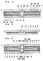
- Fig. 7 shows a measurement result of the modulation factor mf (percentage) to the recording power (mW) of the optical recording disc comprising the under layer 3 made of fluorocarbon polymers and cellulose nitrate.
- A designates the characteristic of the optical recording disc comprising the under layer 3 made of fluorocarbon polymers
- C designates the characteristic of optical recording disc comprising the under layer 3 made of cellulose nitrate.
- the modulation factor mf in the case A of the under layer 3 made of fluorocarbon polymers was larger than the modulation factor mf in the case C of the under layer 3 made of cellulose nitrate at any recording power.
- the projection around the pit was formed uniformly and properly.
- the recording layer 4 made of Te-Se-Pb was formed on the under layer 3 by the aforementioned radio frequency sputtering method.
- the modulation factor mf had the same characteristic as the characteristic in the case of the under layer 3 made of fluorocarbon polymers.
- each of the optical recording disc comprising the under layer 3 made of fluorocarbon polymers and the optical recording disc comprising the under layer 3 made of ultraviolet curing resin was performed for more than 3 months on the condition of a temperature of 60 °C and a relative humidity of 95 percentages. According to the measurement result of the accelerated test, any crack was not formed in the recording layer 4 of the optical recording discs, and the reflection factor of the laser light was not smaller than the aforementioned predetermined threshold value of the reflection factor.
- a disc substrate 1 made of polycarbonate having a diameter of 12.7 cm (5 inches) and a thickness of 1.2 mm was made by the injection molding method, wherein the reterdation of the disc substrate 1 was smaller than 20 nm on the go and return paths.
- the formed disc substrate 1 was set in the sputtering device, and the under layer 3 made of polyimide was formed on one surface 1a of the disc substrate 1 as follows. That is, a Kapton® film was used as a target, the under layer 3 was formed on the condition of an Ar gas pressure of 4 Pa (30 mTorr) and a radio frequency output power of the laser beam of 200 W, resulting in that the under layer 3 having a thickness of approximately 30 nm was obtained. Following to the formation of the under layer 3, the recording layer 4 of Te-Se-Pb having a thickness of approximately 27 nm was formed by the radio frequency sputtering method.
- Fig. 7 shows a measurement result of the modulation factor mf (percentage) to the recording power (mW) of the optical recording disc comprising the under layer 3 made of polyimide.
- mf percentage
- mW recording power
- the modulation factor mf in the case B of the under layer 3 made of polyimide is smaller than the modulation factor mf in the case A of the under layer 3 made of fluorocarbon polymers at any recording power, however, the modulation factor mf in the case B of the under layer 3 made of polyimide is larger than the modulation factor mf in the case C of the under layer 3 made of cellulose nitrate at a larger recording power than approximately 10 mW.
- the aforementioned accelerated test of the optical recording disc comprising the under layer 3 made of polyimide was performed for more than 3 months on the condition of a temperature of 60 °C and a relative humidity of 95 percentages. According to the measurement result of the accelerated test, any crack was not formed in the recording layer 4 of the optical recording discs, and the reflection factor of the laser light was not smaller than the aforementioned predetermined threshold value of the reflection factor.
- a replica layer 5 made of ultraviolet curing resin including the uneven pattern 2 was formed by the 2P method between the disc substrate 1 made of glass or epoxy resin and the under layer 3.
- two cases are known for tracking serve method, one case is that the uneven pattern 2 is formed between the under layer 3 and the recording layer 4, on the other hand, another case is that the uneven pattern 2 is not formed, and Figs. 5 and 6 show the latter case.
- the aforementioned measurement of the modulation factor mf and the aforementioned accelerated test of the optical recording disc of Fig. 5 were formed.
- the same characteristic of the modulation factor mf was obtained as the characteristic of the modulation factor mf of the optical recording disc and the accelerated test, and according to the accelerated test, any crack was not formed in the recording layer 4 of the optical recording discs, and the reflection factor of the laser light was not smaller than the aforementioned predetermined threshold value of the reflection factor.
- a pair of the single sided optical recording discs with the under layer 3 and the replica layer 5 of Fig. 5 may be bonded together through a pair of hub halves 8a and 8b, the inner spacer 6 and the outer spacer 7 so that the recording layers 4 of each of the optical recording discs face each other.
- the hub halves 8a is in the same shape of the hub halves 8b, and center holes 8ah and 8bh for inserting a spindle of a recording and playback device are respectively formed in the center portion of the hub halves 8a and 8b.
- the hub halves 8a comprises a first cylindrical portion 8aa and a second cylindrical portion 8ab, wherein the portions 8aa and 8ab have the same inner diameter, and the portion 8aa has a smaller outer diameter than the outer diameter of the portion 8ab.
- the hub halves 8b has a first cylindrical portion 8ba and a second cylindrical portion 8bb as well as the hub halves 8a. As shown in Fig. 6, the first cylindrical portions 8aa and 8ba are respectively inserted into the center holes 1h of the disc substrates 1, and a pair of hub halves 8a and 8b are bonded together on the bottom surface of the second cylindrical portions 8ab and 8bb thereof.
- the single sided optical recording disc of Fig. 5 and the aforementioned enforcement member may be bonded together through the hub haves 8a and 8b, the inner spacer 6 and the outer spacer 7.
- the under layer 3 is made of the transparent material having a heat resistance superior than the disc substrate 1 and having a lower melting point, a lower decomposing temperature, and a lower heat conductivity than the recording layer 4, resulting in that the under layer 3 can relax the thermal shock transferred from the recording layer 4 through the under layer 3 into the disc substrate 1.
- the output power of the laser beam for playback is preferably larger. In case a semiconductor laser of a wavelength of 830 nm is used, the laser beam having a larger output power than 1 mW is required.
- the under layer 3 In order not to occur the thermal deformation of the disc substrate 1 even though the laser beam for playback having a larger output power than 1 mW is repeatedly radiated onto the the recording layer 4, it is necessary to form the under layer 3 having a heat resistance being proof at a higher temperature than 110 °C. On the other hand, when the under layer 3 has a lower heat conductivity, the recording sensitivity corresponding to the modulation factor mf can be improved. For example, in practical use, the under layer 3 having a smaller heat conductivity than 5 W/mK is required.
- the recording layer 4 is made of a metal having a low melting point mainly including Te
- the under layer 3 is preferably made of polytetrafluoroethylene.
- Table 1 shows materials of the disc substrate 1, the recording layer 4, and the under layer 3 applicable to the optical recording disc according to the present invention, and also shows the melting point, the decomposing temperature, and the heat conductivity of those materials.
- the recording layer 4 made of an alloy of TeSe group having a thickness of 30 nm (300 A) was formed on the under layer 3 by the sputtering method, wherein the under layer 3 was formed on the sputtering condition of an Ar gas pressure of 7 x10 ⁇ 1 Pa and a radio frequency output power of 60 W, and the recording layer 4 was formed on the sputtering condition of an Ar gas pressure of 6 x10 ⁇ 1 Pa and a radio frequency output power of 40 W.
- the 5 optical recording discs respectively comprising the under layer 3 having 5 sorts of the thicknesses of 5 nm (50 ⁇ ), 10 nm (100 ⁇ ), 20 nm (200 ⁇ ), 40 nm (400 ⁇ ) and 80 nm (800 ⁇ ) were formed by the aforementioned method, wherein each of the 5 optical recording discs is respectively referred to hereinafter as the experimental examples 3 to 7.
- Table 2 shows the measurement result of the maximum output power of the laser beam when the the detected signal changes in the range of +10 percentages to -10 percentages of the signal level (referred to hereinafter as the maximum output power of the laser beam) in the 5 optical recording discs comprising the under layer 3 having 5 sorts of the thicknesses.
- the maximum output power of the laser beam after the laser beam having a wavelength of 830 nm was repeatedly radiated onto the recording layer 4 at a repeat cycle of 1200 /min. for 10 hours, the information signal recorded in the recording layer 4 was read out, and the maximum output power of the laser beam when the the detected signal changes in the range of +10 percentages to -10 percentages of the signal level was measured.
- Table 2 the measurement result of the maximum output power of the laser beam in the case of the optical recording disc without the under layer 3 is also shown as the comparative example.
- This measurement was performed for the following reason. That is, when the laser beam having a large output power is radiated through the disc substrate 1, the uneven pattern 2, and the under layer 3 onto the recording layer 4, and the uneven pattern 2 is deformed by the deformation of the disc substrate 1, the light beam radiated onto the recording layer 4 may be not reflected properly, resulting in that the information signal included in the reflected laser beam may not be detected properly by the receiver in the recording and playback device. Therefore, even though a larger output power of the laser beam is radiated onto the recording layers 4, the maximum output power of the laser beam, when the uneven pattern 2 is not deformed and a predetermined variation of the detected signal can be obtained, is required.
- the maximum output power of the laser beam of each of the 4 optical recording discs comprising the under layer 3 except for the experimental example 3 was larger than the maximum output power of the laser beam of the comparative example of the optical recording disc without the under layer 3, and when the optical recording disc had the thicker under layer 3, the maximum output power of the laser beam increases, resulting in that the effect for preventing the deformation of the uneven pattern 2 could be improved.
- the output power of the laser beam is preferably large, and the output power of the laser beam is preferably larger than 1 mW.
- the under layer 3 is made of polytetrafluoroethylene, the under layer 3 having a larger thickness than 20 nm (200 ⁇ ) is preferably formed.
- Fig. 8 shows the measurement result of the modulation factor mf (percentage) to the recording power (mW) of the 5 optical recording discs with the under layer 3 of the aforementioned experimental examples 3 to 7 and the optical recording disc without the under layer 3 of the aforementioned comparative example.
- the wavelength of the laser beam was 830 nm
- the pulse width was 100 nsec
- the optical recording disc was driven to rotate at a rotation speed of 1200 rpm
- the line velocity on the rotating optical recording disc was 7.1 m/sec.
- the modulation factor mf of each of the optical recording discs with the under layer 3 of the experimental examples 3 to 7 was larger than the modulation factor mf of the optical recording disc without the under layer 3 of the comparative example at a smaller recording power than approximately 6.8 mW, therefore, it was understood that the pit could be easily formed in the recording layer 4 of the optical recording discs with the under layer 3.
- the ratio of the modulation factor mf to the recording power at a lower recording power was larger than the ratio at a higher recording power.
- the laser beam having an output power of 20 mW (corresponding to the recording power of 6 mW to 8 mW) is widely used, therefore, in particular, the optical recording discs of the experimental examples 5 to 7 are effective in using as the optical recording disc in the optical recording and playback device.
- a replica layer 5 made of ultraviolet curing resin was coated on the bottom surface 1a of the disc substrate 1 made of glass, the replica layer 5 was expanded by the known method, and the pregrooves corresponding to the tracking information signal and the prepits corresponding to the address information were transferred onto the bottom surface of the replica layer 5.
- a under layer 3 made of polychlorotrifluoroethylene having a thickness of approximately 20 nm (200 ⁇ ) was formed on the replica layer 5 by the radio frequency sputtering method
- a recording layer 4 made of Te - Se group having a thickness of approximately 30 nm (300 ⁇ ) was formed on the under layer 3 by the radio frequency sputtering method.
- the optical recording disc with the replica layer 5 and the under layer 3 of polychlorotrifluoroethylene is referred to hereinafter as the experimental example 8.
- the replica layer 5 made of ultraviolet curing resin where the pregrooves and the prepits were transferred was formed on the bottom surface 1a of the disc substrate 1. Then, after a layer 3 made of polycarbon monofluoride having a thickness of approximately 20 nm (200 ⁇ ) was formed on the replica layer 5 by the radio frequency sputtering method, a recording layer 4 made of Te - Se group having a thickness of approximately 30 nm (300 ⁇ ) was formed on the under layer 3 by the radio frequency sputtering method.
- the optical recording disc with the replica layer 5 and the under layer 3 of polycarbon monofluoride is referred to hereinafter as the experimental example 9.
- the replica layer 5 made of ultraviolet curing resin where the pregrooves and the prepits were transferred was formed on the bottom surface 1a of the disc substrate 1. Then, after a layer 3 made of polyvinylidene fluoride having a thickness of approximately 20 nm (200 ⁇ ) was formed on the replica layer 5 by the radio frequency sputtering method, a recording layer 4 made of Te - Se group having a thickness of approximately 30 nm (300 ⁇ ) was formed on the under layer 3 by the radio frequency sputtering method.
- the optical recording disc with the replica layer 5 and the under layer 3 of polyvinylidene fluoride is referred to hereinafter as the experimental example 10.
- the replica layer 5 made of ultraviolet curing resin where the pregrooves and the prepits were transferred was formed on the bottom surface 1a of the disc substrate 1. Then, after a layer 3 made of polyhexafluoropropylene having a thickness of approximately 20 nm (200 ⁇ ) was formed on the replica layer 5 by the radio frequency sputtering method, a recording layer 4 made of Te - Se group having a thickness of approximately 30 nm (300 ⁇ ) was formed on the under layer 3 by the radio frequency sputtering method.
- the optical recording disc with the replica layer 5 and the under layer 3 of polyhexafluoropropylene is referred to hereinafter as the experimental example 11.
- Fig. 9 shows the measurement result of the modulation factor mf (percentage) to the recording power (mW) of the 6 optical recording discs with the replica 5 and the under layer 3 of the aforementioned experimental examples 2, 5 and 8 to 11, and the optical recording disc without the under layer 3 of the comparative example.
- B designates the modulation factor characteristic of the optical recording disc with the under layer 3 made of polyimide of the experimental example 2
- D designates the modulation factor characteristic of the optical recording disc with the under layer 3 made of polytetrafluoroethylene of the experimental example 5
- E designates the modulation factor characteristic of the optical recording disc with the under layer 3 made of polychlorotrifluoroethylene of the experimental example 8
- F designates the modulation factor characteristic of the optical recording disc with the under layer 3 made of polycarbon monofluoride of the experimental example 9
- G designates the modulation factor characteristic of the optical recording disc with the under layer 3 made of polyvinylidene fluoride of the experimental example 10
- H designates the modulation factor characteristic of the optical recording disc with the under layer 3 made of polyhexafluoropropylene of the experimental example 11.
- the wavelength of the laser beam was 830 nm
- the pulse width was 100 nsec
- the optical recording disc was driven to rotate at a rotation speed of 600 rpm
- the line velocity on the rotating optical recording disc was 5.1 m/sec.
- the modulation factor mf of each of the optical recording discs with the under layer 3 of the experimental examples 2, 5 and 8 to 11 was larger than the modulation factor mf of the optical recording disc without the under layer 3 of the comparative example at any recording power, therefore, it was understood that the pit can be easily formed in the recording layer 4 of the optical recording discs with the under layer 3.
- the modulation characteristic of the optical recording disc with the under layer 3 made of polytetrafluoroethylene was most superior in the experimental examples 2, 5 and 8 to 11.
- the modulation characteristic of each of the optical recording discs with the under layer 3 was superior in the order of the optical recording disc with the under layer 3 made of polyvinylidene fluoride of the experimental example 10, the optical recording disc with the under layer 3 made of polycarbon monofluoride of the experimental example 9, the optical recording disc with the under layer 3 made of polyhexafluoropropylene of the experimental example 11, and the optical recording disc with the under layer 3 made of polychlorotrifluoroethylene fluoride of the experimental example 8, therefore, the pit can be easily formed in the recording layer 4 in this order.
- the ratio of the modulation factor mf to the recording power at a lower recording power is larger than the ratio at a higher recording power as well as the characteristic of Fig. 6.
- the laser beam having an output power of 20 mW (corresponding to the recording power of 6 mW to 8 mW) is widely used, therefore, in particular, the optical recording discs of the experimental examples 5 and 8 to 11 are effective in using as the optical recording disc in the optical recording and playback device.
- the subject matter of the present invention is to form the under layer 3 made of a high polymeric material having a lower melting point, a lower composing temperature, and a lower heat conductivity than the recording layer 4, between the disc substrate 1 and the recording layer 4, the material of the under layer 3 is not limited to the aforementioned material of the experimental examples 1 to 11.
Description
- The present invention relates to a process for the manufacture of an optical recording medium for recording and playing back an information signal by radiating a light beam thereon and a method of the production thereof.
- Fig. 1 shows one example of this sort of a single sided optical recording disc, and Fig. 2 is an enlarged cross sectional view of the center portion thereof. In Figs. 1 and 2,
pregrooves 12 corresponding to a tracking signal andprepits 13 corresponding to an address signal are transferred onto one surface of a disc substrate 11 of the optical recording medium, and arecording layer 14 made of a recording material for the heat mode is formed on the transferred surface where thepregrooves 12 and theprepits 13 are formed. Theprepits 13 is formed on thepregrooves 12, and each of the information signals corresponding to the difference between the depths of theprepits 13 and thepregrooves 12 is read out. - In the case that an information signal is recorded in the
recording layer 14 of the optical recording disc, the following process is performed. First of all, a laser beam for tracking is radiated from the side of the disc substrate 11 along thepregrooves 12 and theprepits 13, and the tracking information signal and the address information signal are detected by a receiver in a recording and playback device for detecting the light reflected on therecording layer 14. Next, the laser beam modulated by the predetermined information signal is radiated onto the predetermined track and the predetermined sector, so that the thermal deformation such as melting, evaporation, sublimation, and contraction occurs in therecording layer 14, resulting in that pits designating the information signal are formed in therecording layer 14. On the other hand, in the case that the information signal recorded in therecording layer 14 of the optical recording disc is read out, the laser beam is radiated from the side of the disc substrate 11 along thepregrooves 12, the tracking information signal and the address information signal are detected by detecting the light reflected on therecording layer 14, resulting in that the information signal recorded in therecording layer 14 can be detected. - Recently, a high polymeric material such as polymethylmethacrylate (referred to hereinafter as PMMA), polycarbonate (referred to hereinafter as PC), epoxy resin etc. formed by the injection molding method is widely used as the disc substrate 11 provided to this sort of optical recording disc, because the inexpensive high polymeric material can be produced with a high productivity, the material is relatively light and is not easily damaged, and the material can be transferred and dealt easily, etc..
- Accordingly, since the high polymeric material has a relatively low heat resistance, shapes of
pregrooves 12 and theprepits 13 transferred onto the disc substrate 11 may be gradually changed after the laser beam for playback is repeatedly radiated onto therecording layer 14, and the problems, that the contrast between the reflected light decreases and the carrier to noise level ratio (referred to hereinafter as the CN ratio) decreases, have been pointed out. - Conventionally, in order to prevent the thermal deformation of the disc substrate 11 made of the high polymeric material during recording of the information signal, to prevent the projection of the disc substrate 11 around the portion where the recording pits are formed and the deformation of the pits occurred by the projection of the disc substrate 11, and to record an information signal at a high CN ratio, an information recording medium comprising an adiabatic layer with a transparency between the disc substrate 11 and the
recording layer 14 is publicly known (the Japanese patent laid open No. 189356/1982), wherein the adiabatic layer is made of a transparent material having a high heat resistance that the material cannot be deformed at a higher temperature than the temperature of therecording layer 14 when recording, and having a low heat conductivity and the adiabatic effect, for example, the material is made of CuSe and As₂Se₃ etc. including one of Se and S at a larger atomic percentage than 40 atomic percentage. - As the other examples, ultraviolet curing resin (the Japanese patent laid open No. 86756/1978) and cellulose nitrate (the Japanese patent laid open No. 55544/1982) are known. In the forming method of the layer made of the ultraviolet curing resin or the cellulose nitrate, the rotating and coating method or the vacuum evaporation method is normally used. In this case, a thin layer made of Te group is used as the material of the
recording layer 14, and an organic compound such as ultraviolet curing resin, cellulose nitrate etc. which can be coated by the rotating and coating method is used as an under layer arranged under therecording layer 14.
DE-A-29 35 859 describes an optical recording medium which comprises a substrate, a recording layer and an underlayer. The optical recording medium is provided with an underlayer between the disc substrate and the recording layer. The underlayer is made of a high polymeric material having a lower melting point, a lower decomposition temperature and a lower heat conductivity than the recording layer and the layers are made by vacuum evaporation method. - According to the study by the inventors of the present invention, the characteristic of the heat resistance of the under layer formed under the
recording layer 14 remarkably influences the recording sensitivity of therecording layer 14, and it is found that the thermal deformation of therecording layer 14 is facilitated by the thermal deformation of the under layer which is the disc substrate 11, that is, the recording sensitivity of therecording layer 14 remarkably decreases when the thermal deformation does not occur at all. For example, in the case that therecording layer 14 is formed on the disc substrate 11 made of glass, the recording sensitivity remarkably decreases as compared that the case that therecording layer 14 is formed on the disc substrate 11 made of PMMA. Accordingly, as the aforementioned known example, when the adiabatic layer whose thermal deformation does not occur at all at a recording temperature is formed between the disc substrate 11 and therecording layer 14, the thermal deformation of the disc substrate 11 can be prevented and the decrease of the CN ratio can be prevented. However, the recording sensitivity remarkably decreases, and there is a problem that the laser power must be increased. - For example, in the case that ultraviolet curing resin is used as the under layer, there is a problem that the recording sensitivity decreases. On the other hand, in the case that cellulose nitrate is used as the under layer, the recording sensitivity does not decrease, however, it is necessary to perform the troublesome rotating and coating process with a relatively low productivity, and it is difficult to form the under layer made of cellulose nitrate uniformly with a thickness. Moreover, recently, the forming method of recording layer made of Te group is widely used as the sputtering method, therefore, the rotating and coating method is not desirable method.
- An essential object of the present invention is to provide a production method for an optical recording medium with a relatively high productivity, the optical recording medium having a substrate not deformed and having a larger recording sensitivity than the optical recording disc of the prior art, even though a laser beam for playback is repeatedly radiated onto a recording layer. The invention is defined in the claims.
- The production method of the optical recording medium comprising a process of forming an under layer on an uneven pattern of a substrate on a predetermined vacuum condition in a tank, and a process of forming a recording layer on said under layer on the predetermined vacuum condition in said tank continuously after the process of forming said under layer.
- Accordingly, said under layer can relax the thermal shock transferred from said substrate into the recording layer, and the deformation of said substrate can be prevented, even though a laser beam for playback is repeatedly radiated onto said recording layer, and the optical recording medium has a larger recording sensitivity than the recording sensitivity of the optical recording medium of the prior art. Therefore, even though the output power of the laser beam for playback is a relatively small, the information signal recorded in said recording layer can be read out properly.
- Moreover, since the production method of said optical recording medium does not comprise the rotating and coating method and comprises only the sputtering process, the productivity can be improved, resulting in that the cost of the production can be reduced.
- Fig. 1 is a cross sectional view of a single sided optical recording disc of a prior art,
- Fig. 2 is enlarged cross sectional view of the center portion of the single sided optical recording disc of Fig. 1,
- Fig. 3 is a cross sectional view of a single sided optical recording disc with an under layer according to the present invention,
- Fig. 4 is a cross sectional view of a dual sided optical recording disc with an under layer according to the present invention,
- Fig. 5 is a cross sectional view of a single sided optical recording disc with an under layer and a replica layer according to the present invention,
- Fig. 6 is a cross sectional view of a dual sided optical recording disc with an under layer and a replica layer according to the present invention,
- Fig. 7 is a graph of the modulation factor mf to the recording power of optical recording discs with an under layer of experimental examples 1 and 2 according to the present invention and an optical recording disc with an under layer made of cellulose nitrite of a comparative example,
- Fig. 8 is a graph of the modulation factor mf to the recording power of optical recording discs with an under layer made of polytetrafluoroethylene of experimental examples 3 and 7 according to the present invention and an optical recording disc without the under layer of a comparative example, and
- Fig. 9 is a graph of the modulation factor mf to the recording power of optical recording discs with an under layer of experimental examples 2, 6 and 8 to 11 according to the present invention and the optical recording disc without the under layer of the comparative example.
- Fig. 3 shows a direct read after write type and single sided type optical recording disc of a first preferred embodiment according to the present invention. In Fig. 3, 1 denotes a disc substrate, a
center hole 1h is formed for inserting a spindle of a recording and playback device in the center portion of thedisc substrate 1, and anuneven pattern 2 is formed on the bottom surface 1a of thedisc substrate 1. An underlayer 3 is formed on theuneven pattern 2 of thedisc substrate 1, and arecording layer 4 is formed on the underlayer 3, wherein thebottom surface 3a of the underlayer 3 is made uneven or even, each of the top and thebottom surfaces under layer 3 is provided for relaxing the thermal shock from therecording layer 4 into thedisc substrate 1 when the laser beam is repeatedly radiated from the side of the upper surface of thedisc substrate 1 onto therecording layer 4 and playing back the information signal, and the heat occurred in therecording layer 4 by the laser beam is transferred through the underlayer 3 into thedisc substrate 1. - Fig. 4 shows a dual sided optical recording disc of a second preferred embodiment according to the present invention. In Fig. 4, a pair of single sided optical recording discs of Fig. 3 are bonded together through an
inner spacer 6 and anouter spacer 7 so that therecording layers 4 face each other, wherein theinner spacer 6 is bonded on the inner rim portion of thedisc substrate 1, and acenter hole 6h having the same inner diameter as the inner diameter of thecenter hole 1h is formed in the center portion of theinner spacer 6. Moreover, the single sided optical recording disc of Fig. 3 and an enforcement member in the same shape as thedisc substrate 1 may be bonded together through theinner spacer 6 and theouter spacer 7 so that therecording layers 4 face each other. - In Fig. 3 and 4, the
disc substrate 1 is made of a plastic resin material such as PMMA, PC, polyvinyl chloride, polypropylene, acrylic resin, epoxy resin etc.. - The
uneven pattern 2 is formed on the bottom surface 1a of thedisc substrate 1 by a known method such as the photo polymerization method (referred to hereinafter as the 2P method), the injection method, the compression method, or the injection-compression method. - The
recording layer 4 is made of a recording material for the heat mode of one or more elements selected from a group consisting of S, Se, Te, Bi, Sn, Pb, In, Zn, Mg, Au, Ce, Ca, Sb, Rh, Mn, and Al, therecording layer 4 may be formed by a thin film forming method such as the sputtering method etc.. As described above, each of the top and thebottom surfaces - The under
layer 3 is made of thermal decomposing high polymeric material having good transparency, which can be decomposed by heating at a lower temperature than the melting point of therecording layer 4 and producing the gas. Concretely, the material of theunder layer 3 is at least one sort of compounds selected from a group consisting of polyolefine fluoride, halogenide of polyolefine fluoride, and fluorocarbons, and is a material which melts, sublimates and decomposes at a lower second temperature than the first temperature at which the material of therecording layer 4 can be melted, sublimated, or decomposed. For example, in the optical recording medium comprising thedisc substrate 1 made of PMMA, PC or epoxy resin, and therecording layer 4 made of an alloy having a relative low melting point and mainly including Te, in particular, the underlayer 3 is preferably made of one or more high polymeric materials having a low melting point selected from a group consisting of polyolefine fluoride such as polytetrafluoroethylene, polyvinyl fluoride, polytrifluoroethylene, polyvinylidene fluoride, polyhexafluoropropylene, halogenide of polyolefine fluoride such as polychlorotrifluoroethylene, polydichlorodifluoroethylene, fluorocarbons such as polycarbon monofluoride, polydicarbon monofluoride etc., or the modified product of these compounds. The underlayer 3 is formed by the sputtering method, as well as the forming method of therecording layer 4. As described above, thebottom surface 3a of the underlayer 3 is made uneven with forming the prepits and the pregrooves or even without forming the prepits and the pregrooves. - Next, one example of the production method of the direct read after write type optical recording disc according to the present invention.
- First of all, the
disc substrate 1, a material for forming the underlayer 3 and a material for forming therecording layer 4 are placed in a vacuum tank. Next, after the inside of the vacuum tank is made vacuous into the predetermined degree of vacuum, inert gas is supplied into the vacuum tank, and the gas pressure in the inside of the vacuum tank is adjusted to a predetermined pressure value. After that, on the condition of the adjusted gas pressure, the underlayer 3 is formed on one surface 1a of thedisc substrate 1 by the sputtering method using the material for forming the underlayer 3 as a target, and under the same condition of the gas pressure, therecording layer 4 is formed on the surface of the underlayer 3 by the sputtering method using the material for forming therecording layer 4 as a target. - Before the description of the experimental examples proceeds, the measurement method of the recording sensitivity of the
recording layer 4 will be described below in details. The laser beam having a wave length of 830 nm and a pulse width of 100 nsec oscillated by a light generator is radiated from the side of the top surface of thedisc substrate 1 through the underlayer 3 onto therecording layer 4 so that the laser beam is focused on therecording layer 4. Then, when the output power of the laser beam is increased, the power of the laser beam supplied onto the recording layer 4 (referred to hereinafter as the recording power) is increased, and a pit begins to be formed when the recording power is larger than a predetermined threshold power level, wherein the pit designates a digital information signal depend on whether the pit in a predetermined is formed or not. A modulation factor mf is referred to hereinafter as the corresponding value to the size of the pit formed in therecording layer 4 when a predetermined recording power is supplied onto therecording layer 4. That is, the modulation factor mf (percentage) is defined by the following equation.

- In the above equation (1), A is a reflection factor of the laser beam on the portion where the
recording layer 4 is formed and the pit is not formed,
B is a reflection factor of the laser beam on the portion where therecording layer 4 is not formed, and
X is a reflection factor of the laser beam on the portion where the pit is formed by radiating the laser beam having a predetermined recording power. - As shown in the equation (1), the modulation factor mf is defined as the ratio of the reflection factor of the laser beam when the pit is formed to the reflection factor of the laser beam when the pit is not formed. In the measurement of the modulation factor mf, it is judged by the known scanning electron microscope observation method whether or not the pit having a predetermined shape is formed properly.
- In the accelerated test of the life of the pit, the inside of the tank where the optical recording disc comprising the
recording layer 4 is arranged is maintained on the condition of a temperature of 60 °C and a relative humidity of 95 percentages, it is measured whether or not a crack is formed in therecording layer 4 and whether or not the reflection factor of the laser light decreases by the oxidation reaction is smaller than a predetermined threshold value of the reflection factor, wherein the predetermined threshold value of the reflection factor is defined as the maximum value of the reflection factor when the laser light reflected on therecording layer 4 can not be received by the receiver in the recording and playback device. - A
disc substrate 1 made of polycarbonate having a diameter of 12.7 cm (5 inches) and a thickness of 1.2 mm was made by the injection molding method, wherein the reterdation of thedisc substrate 1 was smaller than 20 nm on the go and return paths. The formeddisc substrate 1 was set in the sputtering device, and the underlayer 3 made of fluorocarbon polymers was formed on one surface 1a of thedisc substrate 1 as follows. That is, a Teflon® film was used as a target, the underlayer 3 was formed on the condition of an Ar gas pressure of 4 Pa (30 mTorr) and a radio frequency output power of the laser beam of 200 W, resulting in that the underlayer 3 having a thickness of approximately 30 nm was formed on the surface 1a of thedisc substrate 1. Following to the formation of the underlayer 3, therecording layer 4 of Te-Se-Pb having a thickness of approximately 27 nm was formed by the radio frequency sputtering method. - Fig. 7 shows a measurement result of the modulation factor mf (percentage) to the recording power (mW) of the optical recording disc comprising the under
layer 3 made of fluorocarbon polymers and cellulose nitrate. In Fig. 7, A designates the characteristic of the optical recording disc comprising the underlayer 3 made of fluorocarbon polymers, and C designates the characteristic of optical recording disc comprising the underlayer 3 made of cellulose nitrate. According to the measurement result of Fig. 7, the modulation factor mf in the case A of the underlayer 3 made of fluorocarbon polymers was larger than the modulation factor mf in the case C of the underlayer 3 made of cellulose nitrate at any recording power. In the case of the underlayer 3 of fluorocarbon polymers, the projection around the pit was formed uniformly and properly. - Next, after the under
layer 3 made of ultraviolet curing resin of acrylic resin group having a pattern of the prepits and pregrooves for tracking was formed on thedisc substrate 1 made of glass or epoxy resin, therecording layer 4 made of Te-Se-Pb was formed on the underlayer 3 by the aforementioned radio frequency sputtering method. In this case, the modulation factor mf had the same characteristic as the characteristic in the case of the underlayer 3 made of fluorocarbon polymers. - The aforementioned accelerated test of each of the optical recording disc comprising the under
layer 3 made of fluorocarbon polymers and the optical recording disc comprising the underlayer 3 made of ultraviolet curing resin was performed for more than 3 months on the condition of a temperature of 60 °C and a relative humidity of 95 percentages. According to the measurement result of the accelerated test, any crack was not formed in therecording layer 4 of the optical recording discs, and the reflection factor of the laser light was not smaller than the aforementioned predetermined threshold value of the reflection factor. - A
disc substrate 1 made of polycarbonate having a diameter of 12.7 cm (5 inches) and a thickness of 1.2 mm was made by the injection molding method, wherein the reterdation of thedisc substrate 1 was smaller than 20 nm on the go and return paths. The formeddisc substrate 1 was set in the sputtering device, and the underlayer 3 made of polyimide was formed on one surface 1a of thedisc substrate 1 as follows. That is, a Kapton® film was used as a target, the underlayer 3 was formed on the condition of an Ar gas pressure of 4 Pa (30 mTorr) and a radio frequency output power of the laser beam of 200 W, resulting in that the underlayer 3 having a thickness of approximately 30 nm was obtained. Following to the formation of the underlayer 3, therecording layer 4 of Te-Se-Pb having a thickness of approximately 27 nm was formed by the radio frequency sputtering method. - Fig. 7 shows a measurement result of the modulation factor mf (percentage) to the recording power (mW) of the optical recording disc comprising the under
layer 3 made of polyimide. In Fig. 7, B designates the characteristic of the optical recording disc comprising the underlayer 3 made of polyimide. According to the measurement result of Fig. 7, the modulation factor mf in the case B of the underlayer 3 made of polyimide is smaller than the modulation factor mf in the case A of the underlayer 3 made of fluorocarbon polymers at any recording power, however, the modulation factor mf in the case B of the underlayer 3 made of polyimide is larger than the modulation factor mf in the case C of the underlayer 3 made of cellulose nitrate at a larger recording power than approximately 10 mW. - The aforementioned accelerated test of the optical recording disc comprising the under
layer 3 made of polyimide was performed for more than 3 months on the condition of a temperature of 60 °C and a relative humidity of 95 percentages. According to the measurement result of the accelerated test, any crack was not formed in therecording layer 4 of the optical recording discs, and the reflection factor of the laser light was not smaller than the aforementioned predetermined threshold value of the reflection factor. - Moreover, as shown in Fig. 5, a
replica layer 5 made of ultraviolet curing resin including theuneven pattern 2 was formed by the 2P method between thedisc substrate 1 made of glass or epoxy resin and the underlayer 3. In general, two cases are known for tracking serve method, one case is that theuneven pattern 2 is formed between theunder layer 3 and therecording layer 4, on the other hand, another case is that theuneven pattern 2 is not formed, and Figs. 5 and 6 show the latter case. The aforementioned measurement of the modulation factor mf and the aforementioned accelerated test of the optical recording disc of Fig. 5 were formed. According to the measurement, the same characteristic of the modulation factor mf was obtained as the characteristic of the modulation factor mf of the optical recording disc and the accelerated test, and according to the accelerated test, any crack was not formed in therecording layer 4 of the optical recording discs, and the reflection factor of the laser light was not smaller than the aforementioned predetermined threshold value of the reflection factor. - Furthermore, as shown in Fig. 6, a pair of the single sided optical recording discs with the under
layer 3 and thereplica layer 5 of Fig. 5 may be bonded together through a pair ofhub halves inner spacer 6 and theouter spacer 7 so that the recording layers 4 of each of the optical recording discs face each other. The hub halves 8a is in the same shape of thehub halves 8b, and center holes 8ah and 8bh for inserting a spindle of a recording and playback device are respectively formed in the center portion of the hub halves 8a and 8b. The hub halves 8a comprises a first cylindrical portion 8aa and a second cylindrical portion 8ab, wherein the portions 8aa and 8ab have the same inner diameter, and the portion 8aa has a smaller outer diameter than the outer diameter of the portion 8ab. The hub halves 8b has a first cylindrical portion 8ba and a second cylindrical portion 8bb as well as thehub halves 8a. As shown in Fig. 6, the first cylindrical portions 8aa and 8ba are respectively inserted into the center holes 1h of thedisc substrates 1, and a pair ofhub halves - Moreover, the single sided optical recording disc of Fig. 5 and the aforementioned enforcement member may be bonded together through the
hub haves inner spacer 6 and theouter spacer 7. - The under
layer 3 is made of the transparent material having a heat resistance superior than thedisc substrate 1 and having a lower melting point, a lower decomposing temperature, and a lower heat conductivity than therecording layer 4, resulting in that the underlayer 3 can relax the thermal shock transferred from therecording layer 4 through the underlayer 3 into thedisc substrate 1. In the case that the SN ratio including the noise of the optical system in a recording and playback device for the optical recording disc is taken account into the design of the device, the output power of the laser beam for playback is preferably larger. In case a semiconductor laser of a wavelength of 830 nm is used, the laser beam having a larger output power than 1 mW is required. In order not to occur the thermal deformation of thedisc substrate 1 even though the laser beam for playback having a larger output power than 1 mW is repeatedly radiated onto the therecording layer 4, it is necessary to form the underlayer 3 having a heat resistance being proof at a higher temperature than 110 °C. On the other hand, when the underlayer 3 has a lower heat conductivity, the recording sensitivity corresponding to the modulation factor mf can be improved. For example, in practical use, the underlayer 3 having a smaller heat conductivity than 5 W/mK is required. - Concretely, in the case that the
disc substrate 1 is made of PMMA, PC, or epoxy resin, therecording layer 4 is made of a metal having a low melting point mainly including Te, the underlayer 3 is preferably made of polytetrafluoroethylene. - Table 1 shows materials of the
disc substrate 1, therecording layer 4, and the underlayer 3 applicable to the optical recording disc according to the present invention, and also shows the melting point, the decomposing temperature, and the heat conductivity of those materials. - After the under
layer 3 made of polytetrafluoroethylene was formed by the sputtering method on one surface 1a of thedisc substrate 1 made of PC by the injection molding method, therecording layer 4 made of an alloy of TeSe group having a thickness of 30 nm (300 A) was formed on the underlayer 3 by the sputtering method, wherein the underlayer 3 was formed on the sputtering condition of an Ar gas pressure of 7 x10⁻¹ Pa and a radio frequency output power of 60 W, and therecording layer 4 was formed on the sputtering condition of an Ar gas pressure of 6 x10⁻¹ Pa and a radio frequency output power of 40 W. The 5 optical recording discs respectively comprising the underlayer 3 having 5 sorts of the thicknesses of 5 nm (50 Å), 10 nm (100 Å), 20 nm (200 Å), 40 nm (400 Å) and 80 nm (800 Å) were formed by the aforementioned method, wherein each of the 5 optical recording discs is respectively referred to hereinafter as the experimental examples 3 to 7. - Table 2 shows the measurement result of the maximum output power of the laser beam when the the detected signal changes in the range of +10 percentages to -10 percentages of the signal level (referred to hereinafter as the maximum output power of the laser beam) in the 5 optical recording discs comprising the under
layer 3 having 5 sorts of the thicknesses. In the measurement of the maximum output power of the laser beam, after the laser beam having a wavelength of 830 nm was repeatedly radiated onto therecording layer 4 at a repeat cycle of 1200 /min. for 10 hours, the information signal recorded in therecording layer 4 was read out, and the maximum output power of the laser beam when the the detected signal changes in the range of +10 percentages to -10 percentages of the signal level was measured. In Table 2, the measurement result of the maximum output power of the laser beam in the case of the optical recording disc without the underlayer 3 is also shown as the comparative example. - This measurement was performed for the following reason. That is, when the laser beam having a large output power is radiated through the
disc substrate 1, theuneven pattern 2, and the underlayer 3 onto therecording layer 4, and theuneven pattern 2 is deformed by the deformation of thedisc substrate 1, the light beam radiated onto therecording layer 4 may be not reflected properly, resulting in that the information signal included in the reflected laser beam may not be detected properly by the receiver in the recording and playback device. Therefore, even though a larger output power of the laser beam is radiated onto the recording layers 4, the maximum output power of the laser beam, when theuneven pattern 2 is not deformed and a predetermined variation of the detected signal can be obtained, is required. - As shown in Table 2, the maximum output power of the laser beam of each of the 4 optical recording discs comprising the under
layer 3 except for the experimental example 3 was larger than the maximum output power of the laser beam of the comparative example of the optical recording disc without the underlayer 3, and when the optical recording disc had the thicker underlayer 3, the maximum output power of the laser beam increases, resulting in that the effect for preventing the deformation of theuneven pattern 2 could be improved. - According to the comparison of the measurement of the maximum output power of the laser beam in the experimental examples 3 to 7 in Table 2, when the optical recording disc had the thicker under
layer 3, the effect for relaxing the thermal shock into thedisc substrate 1 could be improved. Moreover, in order to improve the SN ratio of the detected signal, the output power of the laser beam is preferably large, and the output power of the laser beam is preferably larger than 1 mW. For this reason, in the case that the underlayer 3 is made of polytetrafluoroethylene, the underlayer 3 having a larger thickness than 20 nm (200 Å) is preferably formed. - Fig. 8 shows the measurement result of the modulation factor mf (percentage) to the recording power (mW) of the 5 optical recording discs with the under
layer 3 of the aforementioned experimental examples 3 to 7 and the optical recording disc without the underlayer 3 of the aforementioned comparative example. In the measurement of the modulation factor mf, the wavelength of the laser beam was 830 nm, the pulse width was 100 nsec, the optical recording disc was driven to rotate at a rotation speed of 1200 rpm, the line velocity on the rotating optical recording disc was 7.1 m/sec. - As shown in Fig. 8, the modulation factor mf of each of the optical recording discs with the under
layer 3 of the experimental examples 3 to 7 was larger than the modulation factor mf of the optical recording disc without the underlayer 3 of the comparative example at a smaller recording power than approximately 6.8 mW, therefore, it was understood that the pit could be easily formed in therecording layer 4 of the optical recording discs with the underlayer 3. In particular, in the experimental examples 3 to 7, the 3 optical recording discs with the underlayer 3 having a larger thickness than 20 nm (200 Å), corresponding to the experimental examples 5 to 7, were superior in the modulation factor mf than the other experimental examples 3 to 4 and the comparative example. Moreover, as shown in Fig. 8, the ratio of the modulation factor mf to the recording power at a lower recording power was larger than the ratio at a higher recording power. In this sort of normal optical recording and playback device, the laser beam having an output power of 20 mW (corresponding to the recording power of 6 mW to 8 mW) is widely used, therefore, in particular, the optical recording discs of the experimental examples 5 to 7 are effective in using as the optical recording disc in the optical recording and playback device. - As shown in Fig. 5, a
replica layer 5 made of ultraviolet curing resin was coated on the bottom surface 1a of thedisc substrate 1 made of glass, thereplica layer 5 was expanded by the known method, and the pregrooves corresponding to the tracking information signal and the prepits corresponding to the address information were transferred onto the bottom surface of thereplica layer 5. Next, after a underlayer 3 made of polychlorotrifluoroethylene having a thickness of approximately 20 nm (200 Å) was formed on thereplica layer 5 by the radio frequency sputtering method, arecording layer 4 made of Te - Se group having a thickness of approximately 30 nm (300 Å) was formed on the underlayer 3 by the radio frequency sputtering method. The optical recording disc with thereplica layer 5 and the underlayer 3 of polychlorotrifluoroethylene is referred to hereinafter as the experimental example 8. - As well as the experimental example 8, the
replica layer 5 made of ultraviolet curing resin where the pregrooves and the prepits were transferred was formed on the bottom surface 1a of thedisc substrate 1. Then, after alayer 3 made of polycarbon monofluoride having a thickness of approximately 20 nm (200 Å) was formed on thereplica layer 5 by the radio frequency sputtering method, arecording layer 4 made of Te - Se group having a thickness of approximately 30 nm (300 Å) was formed on the underlayer 3 by the radio frequency sputtering method. The optical recording disc with thereplica layer 5 and the underlayer 3 of polycarbon monofluoride is referred to hereinafter as the experimental example 9. - As well as the experimental example 8, the
replica layer 5 made of ultraviolet curing resin where the pregrooves and the prepits were transferred was formed on the bottom surface 1a of thedisc substrate 1. Then, after alayer 3 made of polyvinylidene fluoride having a thickness of approximately 20 nm (200 Å) was formed on thereplica layer 5 by the radio frequency sputtering method, arecording layer 4 made of Te - Se group having a thickness of approximately 30 nm (300 Å) was formed on the underlayer 3 by the radio frequency sputtering method. The optical recording disc with thereplica layer 5 and the underlayer 3 of polyvinylidene fluoride is referred to hereinafter as the experimental example 10. - As well as the experimental example 8, the
replica layer 5 made of ultraviolet curing resin where the pregrooves and the prepits were transferred was formed on the bottom surface 1a of thedisc substrate 1. Then, after alayer 3 made of polyhexafluoropropylene having a thickness of approximately 20 nm (200 Å) was formed on thereplica layer 5 by the radio frequency sputtering method, arecording layer 4 made of Te - Se group having a thickness of approximately 30 nm (300 Å) was formed on the underlayer 3 by the radio frequency sputtering method. The optical recording disc with thereplica layer 5 and the underlayer 3 of polyhexafluoropropylene is referred to hereinafter as the experimental example 11. - Fig. 9 shows the measurement result of the modulation factor mf (percentage) to the recording power (mW) of the 6 optical recording discs with the
replica 5 and the underlayer 3 of the aforementioned experimental examples 2, 5 and 8 to 11, and the optical recording disc without the underlayer 3 of the comparative example. - In Fig. 9, B designates the modulation factor characteristic of the optical recording disc with the under
layer 3 made of polyimide of the experimental example 2,
D designates the modulation factor characteristic of the optical recording disc with the underlayer 3 made of polytetrafluoroethylene of the experimental example 5,
E designates the modulation factor characteristic of the optical recording disc with the underlayer 3 made of polychlorotrifluoroethylene of the experimental example 8,
F designates the modulation factor characteristic of the optical recording disc with the underlayer 3 made of polycarbon monofluoride of the experimental example 9,
G designates the modulation factor characteristic of the optical recording disc with the underlayer 3 made of polyvinylidene fluoride of the experimental example 10, and
H designates the modulation factor characteristic of the optical recording disc with the underlayer 3 made of polyhexafluoropropylene of the experimental example 11. - In the measurement, the wavelength of the laser beam was 830 nm, the pulse width was 100 nsec, the optical recording disc was driven to rotate at a rotation speed of 600 rpm, the line velocity on the rotating optical recording disc was 5.1 m/sec.
- As shown in Fig. 9, the modulation factor mf of each of the optical recording discs with the under
layer 3 of the experimental examples 2, 5 and 8 to 11 was larger than the modulation factor mf of the optical recording disc without the underlayer 3 of the comparative example at any recording power, therefore, it was understood that the pit can be easily formed in therecording layer 4 of the optical recording discs with the underlayer 3. In particular, the modulation characteristic of the optical recording disc with the underlayer 3 made of polytetrafluoroethylene was most superior in the experimental examples 2, 5 and 8 to 11. The modulation characteristic of each of the optical recording discs with the underlayer 3 was superior in the order of the optical recording disc with the underlayer 3 made of polyvinylidene fluoride of the experimental example 10, the optical recording disc with the underlayer 3 made of polycarbon monofluoride of the experimental example 9, the optical recording disc with the underlayer 3 made of polyhexafluoropropylene of the experimental example 11, and the optical recording disc with the underlayer 3 made of polychlorotrifluoroethylene fluoride of the experimental example 8, therefore, the pit can be easily formed in therecording layer 4 in this order. - Moreover, as shown in Fig. 9, the ratio of the modulation factor mf to the recording power at a lower recording power is larger than the ratio at a higher recording power as well as the characteristic of Fig. 6. In this sort of normal optical recording and playback device, the laser beam having an output power of 20 mW (corresponding to the recording power of 6 mW to 8 mW) is widely used, therefore, in particular, the optical recording discs of the experimental examples 5 and 8 to 11 are effective in using as the optical recording disc in the optical recording and playback device.
- The subject matter of the present invention is to form the under
layer 3 made of a high polymeric material having a lower melting point, a lower composing temperature, and a lower heat conductivity than therecording layer 4, between thedisc substrate 1 and therecording layer 4, the material of the underlayer 3 is not limited to the aforementioned material of the experimental examples 1 to 11.
Claims (6)
- Process for the manufacture of an optical recording medium comprising- a disc substrate (1) consisting of a high polymeric material with an uneven surface pattern,- an under layer (3) consisting of a transparent high polymeric material having a heat resistance superior to said substrate material (1), and- a recording layer (4) consisting of a material of the one or more elements selected from a group consisting of S, Se, Te, Bi, Sn, Pb, In, Zn, Mg, Au, Ce, Ca, Sb, Rh, Mn and Al having a melting point, sublimation point or decomposition point higher than the melting point, sublimation point or decomposition point of the under layer (3),whereby the under layer (3) and the recording layer (4) are formed in a continuous process on the substrate by sputtering in a predetermined vacuum condition.
- Process according to claim 1, wherein as the under layer (3), fluorocarbon resin or polyimide is used.
- Process according to claim 1, wherein the recording layer (4) contains Te.
- Process according to claim 2, wherein said high polymeric material of the underlayer (3) is at least one of a polyolefine fluoride and a halogenide of polyolefine fluoride.
- Process according to claim 1, wherein said high polymeric material used for the under layer (3) is resisting melt, decomposition or sublimation at a higher temperature than 110 °C, and has a heat conductivity lower than 5 W/mK.
- Process according to claim 1, wherein the high polymer material of the under layer (3) is resisting melt, decomposition or sublimation at a temperature higher than that of the substrate (1).
Applications Claiming Priority (8)
| Application Number | Priority Date | Filing Date | Title |
|---|---|---|---|
| JP60275112A JPS62137741A (en) | 1985-12-09 | 1985-12-09 | Additional writing type optical information recording disk and its production |
| JP275112/85 | 1985-12-09 | ||
| JP61032977A JPS62192042A (en) | 1986-02-19 | 1986-02-19 | Optical recording medium |
| JP32977/86 | 1986-02-19 | ||
| JP59434/86 | 1986-03-19 | ||
| JP59437/86 | 1986-03-19 | ||
| JP61059437A JPS62219245A (en) | 1986-03-19 | 1986-03-19 | Optical information recording disk |
| JP61059434A JPS62219244A (en) | 1986-03-19 | 1986-03-19 | Optical information recording medium |
Publications (3)
| Publication Number | Publication Date |
|---|---|
| EP0227981A2 EP0227981A2 (en) | 1987-07-08 |
| EP0227981A3 EP0227981A3 (en) | 1988-01-07 |
| EP0227981B1 true EP0227981B1 (en) | 1992-01-08 |
Family
ID=27459720
Family Applications (1)
| Application Number | Title | Priority Date | Filing Date |
|---|---|---|---|
| EP19860116999 Expired - Lifetime EP0227981B1 (en) | 1985-12-09 | 1986-12-06 | Production method of an optical recording medium |
Country Status (4)
| Country | Link |
|---|---|
| US (2) | US4908250A (en) |
| EP (1) | EP0227981B1 (en) |
| KR (1) | KR870006534A (en) |
| DE (1) | DE3683362D1 (en) |
Families Citing this family (15)
| Publication number | Priority date | Publication date | Assignee | Title |
|---|---|---|---|---|
| DE3889619T2 (en) * | 1987-10-27 | 1994-10-13 | Seiko Epson Corp | Information recording plate. |
| US5265086A (en) * | 1987-10-27 | 1993-11-23 | Seiko Epson Corporation | Information recording disk |
| US4960627A (en) * | 1988-04-22 | 1990-10-02 | Mitsui Petrochemical Industries, Ltd. | Optical recording media and process for preparing same |
| US5234792A (en) * | 1988-11-09 | 1993-08-10 | Hitachi Maxell, Ltd. | Optical data recording medium and manufacturing method thereof |
| EP0385341B1 (en) * | 1989-03-03 | 2000-05-24 | TDK Corporation | Optical recording medium |
| US5202881A (en) * | 1989-06-30 | 1993-04-13 | Kabushiki Kaisha Toshiba | Information storage medium |
| DE4017244A1 (en) * | 1990-05-29 | 1991-12-05 | Bayer Ag | MANUFACTURE OF OPTICAL STORAGE MEDIA |
| US5510164A (en) * | 1994-12-16 | 1996-04-23 | International Business Machines Corporation | Single-sided ablative worm optical disk with multilayer protective coating |
| US6764734B2 (en) * | 1998-05-19 | 2004-07-20 | Seagate Technology Llc | High modulus and high damping plastic composite disc substrate for improved servo control by injection and co-injection molding |
| US6319580B1 (en) * | 1998-06-16 | 2001-11-20 | Hitachi Maxell, Ltd. | Recording disk and producing method therefor |
| JP4026234B2 (en) | 1998-06-19 | 2007-12-26 | ソニー株式会社 | Information recording medium |
| FR2848013B1 (en) * | 2002-12-03 | 2005-01-07 | Commissariat Energie Atomique | IRREVERSIBLE OPTICAL RECORDING MEDIUM BASED ON TELLURE AND ZINC ALLOY. |
| US20060121234A1 (en) * | 2004-12-07 | 2006-06-08 | Marshall Field | Systems, compositions, and methods for laser imaging |
| JP5730768B2 (en) * | 2008-09-12 | 2015-06-10 | ブリガム・ヤング・ユニバーシティBrigham Young University | Data storage medium including carbon and metal layers |
| CN106554619A (en) * | 2016-12-02 | 2017-04-05 | 江苏新瑞贝科技股份有限公司 | A kind of printing masterbatch of the manual imitation synthetic fabrics suitable for printing shaping technology |
Family Cites Families (15)
| Publication number | Priority date | Publication date | Assignee | Title |
|---|---|---|---|---|
| DE2935859A1 (en) * | 1978-09-08 | 1980-03-20 | Matsushita Electric Ind Co Ltd | OPTICAL RECORDING PART |
| US4268840A (en) * | 1979-07-27 | 1981-05-19 | Xerox Corporation | Optical recording member |
| JPS5621892A (en) * | 1979-08-01 | 1981-02-28 | Toshiba Corp | Optical recorder and its manufacturing method |
| US4451915A (en) * | 1982-04-15 | 1984-05-29 | Burroughs Corporation | Optical storage system employing a multi-layer optical medium |
| US4451914A (en) * | 1982-04-15 | 1984-05-29 | Burroughs Corporation | Optical storage system employing a multi-layer optical medium |
| EP0107913B1 (en) * | 1982-09-29 | 1988-06-22 | Kabushiki Kaisha Toshiba | Radiation-sensitive carrier body utilized as stamper structure |
| JPS59104996A (en) * | 1982-12-08 | 1984-06-18 | Canon Inc | Optical recording medium |
| US4592939A (en) * | 1982-12-17 | 1986-06-03 | Burroughs Corporation | Method of rendering uniform coating on disks and product |
| US4555472A (en) * | 1983-02-09 | 1985-11-26 | Canon Kabushiki Kaisha | Organic coating film and radiation-sensitive member having the film |
| US4551828A (en) * | 1983-03-18 | 1985-11-05 | Minnesota Mining And Manufacturing Company | Quadrilayer optical draw medium |
| DE3467825D1 (en) * | 1983-08-31 | 1988-01-07 | Toshiba Kk | Method of producing an optical information recording medium |
| US4554562A (en) * | 1983-12-30 | 1985-11-19 | International Business Machines Corporation | Scratch resistant recording materials for electroerosion printing not requiring a lubricant overcoat |
| JPH0766584B2 (en) * | 1986-04-11 | 1995-07-19 | 富士写真フイルム株式会社 | Method for manufacturing magneto-optical recording medium |
| JPH01123590A (en) * | 1987-11-07 | 1989-05-16 | Mitsubishi Electric Corp | Video signal processing circuit |
| JPH01123591A (en) * | 1987-11-09 | 1989-05-16 | Nippon Hoso Kyokai <Nhk> | Stereoscopic television image device |
-
1986
- 1986-12-02 KR KR860010251A patent/KR870006534A/en not_active Application Discontinuation
- 1986-12-06 EP EP19860116999 patent/EP0227981B1/en not_active Expired - Lifetime
- 1986-12-06 DE DE8686116999T patent/DE3683362D1/en not_active Expired - Lifetime
-
1988
- 1988-09-19 US US07/246,925 patent/US4908250A/en not_active Expired - Lifetime
-
1989
- 1989-12-29 US US07/459,243 patent/US5073243A/en not_active Expired - Lifetime
Also Published As
| Publication number | Publication date |
|---|---|
| EP0227981A2 (en) | 1987-07-08 |
| US4908250A (en) | 1990-03-13 |
| EP0227981A3 (en) | 1988-01-07 |
| US5073243A (en) | 1991-12-17 |
| DE3683362D1 (en) | 1992-02-20 |
| KR870006534A (en) | 1987-07-13 |
Similar Documents
| Publication | Publication Date | Title |
|---|---|---|
| EP0227981B1 (en) | Production method of an optical recording medium | |
| US4998239A (en) | Optical information recording medium containing a metal alloy as a reflective material | |
| US5016240A (en) | Optical recording medium | |
| EP0058496B1 (en) | Protuberant optical recording medium | |
| US6287660B1 (en) | Optical recording medium and its substrate | |
| EP0353394B1 (en) | Optical information recording method and medium | |
| EP0084729A1 (en) | Recording elements | |
| US4470053A (en) | Protuberant optical recording medium | |
| EP0345273B1 (en) | Optical recording medium | |
| US4539572A (en) | Optical recording medium | |
| EP0182670B1 (en) | Optical recording medium | |
| US5326660A (en) | Erasable optical recording media | |
| EP0240800A2 (en) | Optical recording disc | |
| JP3286501B2 (en) | Information recording medium initialization method | |
| EP0253401B1 (en) | Optical recording disc | |
| JP2737401B2 (en) | Optical information recording medium | |
| JPS6325849A (en) | Optical information recording disk | |
| JPH0312839A (en) | Film forming method by sputtering and sputtering device used therein | |
| JPS62219245A (en) | Optical information recording disk | |
| JPS5898290A (en) | Optical recording meterial | |
| JPS59119550A (en) | Information recording member | |
| JPH06223408A (en) | Optical information recording medium | |
| JPH05342633A (en) | Organic optical recording medium and its production | |
| JPS62219244A (en) | Optical information recording medium | |
| JPS62245543A (en) | Substrate for information recording medium |
Legal Events
| Date | Code | Title | Description |
|---|---|---|---|
| PUAI | Public reference made under article 153(3) epc to a published international application that has entered the european phase |
Free format text: ORIGINAL CODE: 0009012 |
|
| AK | Designated contracting states |
Kind code of ref document: A2 Designated state(s): DE FR GB NL |
|
| PUAL | Search report despatched |
Free format text: ORIGINAL CODE: 0009013 |
|
| AK | Designated contracting states |
Kind code of ref document: A3 Designated state(s): DE FR GB NL |
|
| 17P | Request for examination filed |
Effective date: 19880705 |
|
| 17Q | First examination report despatched |
Effective date: 19890321 |
|
| GRAA | (expected) grant |
Free format text: ORIGINAL CODE: 0009210 |
|
| AK | Designated contracting states |
Kind code of ref document: B1 Designated state(s): DE FR GB NL |
|
| REF | Corresponds to: |
Ref document number: 3683362 Country of ref document: DE Date of ref document: 19920220 |
|
| ET | Fr: translation filed | ||
| PLBE | No opposition filed within time limit |
Free format text: ORIGINAL CODE: 0009261 |
|
| STAA | Information on the status of an ep patent application or granted ep patent |
Free format text: STATUS: NO OPPOSITION FILED WITHIN TIME LIMIT |
|
| 26N | No opposition filed | ||
| PGFP | Annual fee paid to national office [announced via postgrant information from national office to epo] |
Ref country code: GB Payment date: 19991126 Year of fee payment: 14 |
|
| PGFP | Annual fee paid to national office [announced via postgrant information from national office to epo] |
Ref country code: DE Payment date: 19991228 Year of fee payment: 14 |
|
| PGFP | Annual fee paid to national office [announced via postgrant information from national office to epo] |
Ref country code: FR Payment date: 19991229 Year of fee payment: 14 |
|
| PGFP | Annual fee paid to national office [announced via postgrant information from national office to epo] |
Ref country code: NL Payment date: 19991231 Year of fee payment: 14 |
|
| PG25 | Lapsed in a contracting state [announced via postgrant information from national office to epo] |
Ref country code: GB Free format text: LAPSE BECAUSE OF NON-PAYMENT OF DUE FEES Effective date: 20001206 |
|
| PG25 | Lapsed in a contracting state [announced via postgrant information from national office to epo] |
Ref country code: NL Free format text: LAPSE BECAUSE OF NON-PAYMENT OF DUE FEES Effective date: 20010701 |
|
| GBPC | Gb: european patent ceased through non-payment of renewal fee |
Effective date: 20001206 |
|
| PG25 | Lapsed in a contracting state [announced via postgrant information from national office to epo] |
Ref country code: FR Free format text: LAPSE BECAUSE OF NON-PAYMENT OF DUE FEES Effective date: 20010831 |
|
| NLV4 | Nl: lapsed or anulled due to non-payment of the annual fee |
Effective date: 20010701 |
|
| REG | Reference to a national code |
Ref country code: FR Ref legal event code: ST |
|
| PG25 | Lapsed in a contracting state [announced via postgrant information from national office to epo] |
Ref country code: DE Free format text: LAPSE BECAUSE OF NON-PAYMENT OF DUE FEES Effective date: 20011002 |