EP0227423A2 - Optical thin film flakes, replicated optical coatings and coatings and inks incorporating the same and method - Google Patents
Optical thin film flakes, replicated optical coatings and coatings and inks incorporating the same and method Download PDFInfo
- Publication number
- EP0227423A2 EP0227423A2 EP86309838A EP86309838A EP0227423A2 EP 0227423 A2 EP0227423 A2 EP 0227423A2 EP 86309838 A EP86309838 A EP 86309838A EP 86309838 A EP86309838 A EP 86309838A EP 0227423 A2 EP0227423 A2 EP 0227423A2
- Authority
- EP
- European Patent Office
- Prior art keywords
- ink
- flakes
- optically variable
- thin film
- coating
- Prior art date
- Legal status (The legal status is an assumption and is not a legal conclusion. Google has not performed a legal analysis and makes no representation as to the accuracy of the status listed.)
- Granted
Links
Images

Classifications
-
- C—CHEMISTRY; METALLURGY
- C09—DYES; PAINTS; POLISHES; NATURAL RESINS; ADHESIVES; COMPOSITIONS NOT OTHERWISE PROVIDED FOR; APPLICATIONS OF MATERIALS NOT OTHERWISE PROVIDED FOR
- C09D—COATING COMPOSITIONS, e.g. PAINTS, VARNISHES OR LACQUERS; FILLING PASTES; CHEMICAL PAINT OR INK REMOVERS; INKS; CORRECTING FLUIDS; WOODSTAINS; PASTES OR SOLIDS FOR COLOURING OR PRINTING; USE OF MATERIALS THEREFOR
- C09D11/00—Inks
- C09D11/50—Sympathetic, colour changing or similar inks
-
- B—PERFORMING OPERATIONS; TRANSPORTING
- B05—SPRAYING OR ATOMISING IN GENERAL; APPLYING FLUENT MATERIALS TO SURFACES, IN GENERAL
- B05D—PROCESSES FOR APPLYING FLUENT MATERIALS TO SURFACES, IN GENERAL
- B05D5/00—Processes for applying liquids or other fluent materials to surfaces to obtain special surface effects, finishes or structures
- B05D5/06—Processes for applying liquids or other fluent materials to surfaces to obtain special surface effects, finishes or structures to obtain multicolour or other optical effects
-
- B—PERFORMING OPERATIONS; TRANSPORTING
- B41—PRINTING; LINING MACHINES; TYPEWRITERS; STAMPS
- B41M—PRINTING, DUPLICATING, MARKING, OR COPYING PROCESSES; COLOUR PRINTING
- B41M3/00—Printing processes to produce particular kinds of printed work, e.g. patterns
-
- B—PERFORMING OPERATIONS; TRANSPORTING
- B41—PRINTING; LINING MACHINES; TYPEWRITERS; STAMPS
- B41M—PRINTING, DUPLICATING, MARKING, OR COPYING PROCESSES; COLOUR PRINTING
- B41M3/00—Printing processes to produce particular kinds of printed work, e.g. patterns
- B41M3/14—Security printing
-
- C—CHEMISTRY; METALLURGY
- C03—GLASS; MINERAL OR SLAG WOOL
- C03C—CHEMICAL COMPOSITION OF GLASSES, GLAZES OR VITREOUS ENAMELS; SURFACE TREATMENT OF GLASS; SURFACE TREATMENT OF FIBRES OR FILAMENTS MADE FROM GLASS, MINERALS OR SLAGS; JOINING GLASS TO GLASS OR OTHER MATERIALS
- C03C17/00—Surface treatment of glass, not in the form of fibres or filaments, by coating
-
- C—CHEMISTRY; METALLURGY
- C09—DYES; PAINTS; POLISHES; NATURAL RESINS; ADHESIVES; COMPOSITIONS NOT OTHERWISE PROVIDED FOR; APPLICATIONS OF MATERIALS NOT OTHERWISE PROVIDED FOR
- C09C—TREATMENT OF INORGANIC MATERIALS, OTHER THAN FIBROUS FILLERS, TO ENHANCE THEIR PIGMENTING OR FILLING PROPERTIES ; PREPARATION OF CARBON BLACK ; PREPARATION OF INORGANIC MATERIALS WHICH ARE NO SINGLE CHEMICAL COMPOUNDS AND WHICH ARE MAINLY USED AS PIGMENTS OR FILLERS
- C09C1/00—Treatment of specific inorganic materials other than fibrous fillers; Preparation of carbon black
- C09C1/0015—Pigments exhibiting interference colours, e.g. transparent platelets of appropriate thinness or flaky substrates, e.g. mica, bearing appropriate thin transparent coatings
-
- C—CHEMISTRY; METALLURGY
- C09—DYES; PAINTS; POLISHES; NATURAL RESINS; ADHESIVES; COMPOSITIONS NOT OTHERWISE PROVIDED FOR; APPLICATIONS OF MATERIALS NOT OTHERWISE PROVIDED FOR
- C09C—TREATMENT OF INORGANIC MATERIALS, OTHER THAN FIBROUS FILLERS, TO ENHANCE THEIR PIGMENTING OR FILLING PROPERTIES ; PREPARATION OF CARBON BLACK ; PREPARATION OF INORGANIC MATERIALS WHICH ARE NO SINGLE CHEMICAL COMPOUNDS AND WHICH ARE MAINLY USED AS PIGMENTS OR FILLERS
- C09C1/00—Treatment of specific inorganic materials other than fibrous fillers; Preparation of carbon black
- C09C1/0078—Pigments consisting of flaky, non-metallic substrates, characterised by a surface-region containing free metal
-
- F—MECHANICAL ENGINEERING; LIGHTING; HEATING; WEAPONS; BLASTING
- F24—HEATING; RANGES; VENTILATING
- F24S—SOLAR HEAT COLLECTORS; SOLAR HEAT SYSTEMS
- F24S70/00—Details of absorbing elements
- F24S70/20—Details of absorbing elements characterised by absorbing coatings; characterised by surface treatment for increasing absorption
Definitions
- This invention relates to optical thin film flakes and coatings and inks incorporating the same and a method for making the same and more particularly to optically variable thin film flakes and inks incorporating the same used in anti-counterfeiting applications.
- FIG. l A process for making an optically variable ink (OVI) is shown in Figure l.
- the flexible web is coated with a solvent soluble polymer.
- the web is formed of a suitable insoluble flexible material using polyethyleneterphthalate (PET), or alternatively, using polymers such as polycarbonates and Kapton.
- PET polyethyleneterphthalate
- a l42 gauge polyester web can be utilized.
- the web is coated with an acrylic based polymer.
- One acrylic based polymer found to be satisfactory is one designated as 5l7-l and is manufactured and sold by Thermark Division of Avery International located at Schererville, Indiana.
- the acrylic based polymer is applied to the web in a suitable manner such as by gravure coating and dried in force air dryers.
- the polymer coat applied to the web is soluble in at least one solvent.
- suitable solvents are acetone and methethylketone.
- other than acrylic polymers other materials can be utilized for a release layer.
- a soluble hardcoat as provided by the acrylic polymer, it is possible to evaporate a thin film coating onto the web which would be soluble in certain liquids.
- Such a thin layer could be sodium fluoride or sodium chloride which could be dissolved with water.
- release layers which have very low adhesion could be utilized which would permit mechanical removal of the optically variable thin film either by the use of a vacuum or by the use of air jets.
- the flexible web can be placed in a vacuum coating chamber for performing the vacuum coating step consisting of depositing an optically variable device (OVD) or optical thin film onto the web as shown by step 202.
- OTD optically variable device
- the optical variable device can be an optical multilayer structure of the type hereinbefore described. Alternatively, it can be of the type described in co-pending applications EP-A-0170439 and U.S. No.640,l4l, filed on July l3, l984.
- Optical variable devices of this character can be deposited onto the web in a conventional manner in a vacuum chamber such as by the use of electron beam and resistive heating sources as well as by sputtering.
- the soluble polymer layer and the adhering thin film which forms the optically variable device is stripped from the carrier web.
- This can be accomplished batch wise or in a continuous fashion as shown by step 203 by passing the web through a bath of a suitable solvent, such as acetone.
- a suitable solvent such as acetone.
- the thin film is separated from the web mechanically.
- the thin film breaks into optical flakes which are of a size on the order of 50 to 200 microns. If a continuous process is being used, the web as it emerges from the solvent, can be engaged by a metal doctor blade to mechanically separate any remaining thin film from the web.
- optical flakes after they have been removed from the carrier web either in a batch process or a continuous process are then reduced in size as hereinafter described and formulated into an ink as shown by step 203. Thereafter, the ink can be utilized in various printing processes as shown by step 204.
- FIG. 2 A more detailed manufacturing process for making optically variable ink from an optical variable device manufactured in the manner hereinbefore described is shown in Figure 2.
- the soluble polymer coated web or substrate is prepared in step 206 as hereinafter described.
- the coated web is then supplied to a vacuum roll coater in roll form as shown in the step 207.
- a thin film multilayer coating can be applied over a given width using a single evaporation source with appropriate masking or can be applied to almost the full width of the vacuum roll coater using multiple evaporative sources and appropriate masking.
- the web is removed from the roll coater and is slit to remove any defects or unwanted trim (edge non-uniformities).
- the spectral properties of the thin film coating can be ascertained and supplied to a computer to provide a running color average of the coating.
- By having available a color profile extending along the width and length of the web it is possible to ascertain the average color of each given roll.
- this desired wavelength can be obtained by adding some lower wavelength material having a wavelength of 485 microns to achieve the desired 490 microns.
- the thin film is stripped from the web.
- this can be accomplished by taking the rolls and placing the rolls on an unwind roller and having the web pass through a solvent bath and then being taken up by a wind-up roller.
- the web as it passes through the solvent bath can pass through a series of rollers which are positioned below the level of the solvent bath. If any of the thin film coating still remains on the web as it emerges from the rollers in the bath, this remaining thin film can be removed by a metal doctor blade which scrapes the remaining thin film from the web.
- the doctor blade typically is positioned on the outside of the roll on the wind-up side so that any adhering flake will fall back into the solvent bath. As explained previously, the flakes in this operation have a tendency to drop off in sizes of approximately 50 to 200 microns.
- the flakes as they fall from the web will fall to the bottom of the tank containing the solvent because they have a much higher specific gravity as, for example, approximately 3 whereas the solvent has a specific gravity of approximately l.
- the clear solvent liquid above the flakes can be drained from the upper part of the tank containing the solvent.
- the flakes can then be removed from the tank and used as hereinafter described.
- the flakes with the remaining solvent can then be filtered and pulled dry as shown by step 2l2 by the use of a vacuum filter of a conventional type. Thereafter, fresh solvent is sprayed over the optically variable flakes forming the filter cake remaining in the filter to remove any last traces of the soluble polymer or other extraneous material from the flakes.
- the filter cake is then removed from the filter and broken up and then laid out to dry in an air oven at atmospheric pressure at a suitable temperature as, for example, l00 for a period of time ranging from approximately 8 to l0 hours as also shown by step 2l2.
- the flakes After the flakes have been dried, they are placed in a suitable solvent solution, such as acetone or methanol and ultrasonically agitated using a conventional ultrasonic agitator as, for example, a Branson sonic dismembrator for a suitable period as, for example, approximately l hour to reduce the particle size to approximately 2-20 microns. Thereafter, the flakes are again filtered to remove the solvent and are air-dryed in an atmospheric oven at a suitable temperature, as for example, 75 overnight or until they are dry.
- a suitable solvent solution such as acetone or methanol
- a conventional ultrasonic agitator as, for example, a Branson sonic dismembrator
- the flakes are again filtered to remove the solvent and are air-dryed in an atmospheric oven at a suitable temperature, as for example, 75 overnight or until they are dry.
- the dryed flakes are subjected to an air grind in a suitable impact pulverizer such as one manufactured by Garlock Plastomer Products, a division of Colt Industries on Friends Lane, Newton, Pennsylvania l8940.
- a suitable impact pulverizer such as one manufactured by Garlock Plastomer Products, a division of Colt Industries on Friends Lane, Newton, Pennsylvania l8940.
- a TX laboratory model of the air impact pulverizer has been utilized to grind alumina up to a rate of 8 pounds an hour using a l0 mesh feed to produce particle sizes down to sub micron size, as for example, 0.65 microns. It has been found by using this air impact pulverizer, 2 to 5 micron size can be readily achieved without destroying the color characteristics of the flakes. It should be appreciated that other grinding techniques can be utilized. However, care must be taken so that the grinding will not destroy the color characteristics of the flakes.
- a particularly attractive feature of the air impact process for producing the small size optically variable thin film flakes is that an aspect ratio of at least 2 to l can be achieved, and a fairly narrow particle size distribution can be obtained.
- the aspect ratio is ascertained by taking the largest dimension of a surface of the flake parallel to the planes of the layers of the thin film and a surface (the thickness) perpendicular to the planes of the layers.
- the air impact process eliminates the need for additional solvent dispersal and solvent removal steps.
- step 2l3 This sizing and blending process is represented by step 2l3 in Figure 2.
- the sized and blended flakes are then introduced into an ink polymer vehicle which consists of a main vehicle with various additives in Step 2l3.
- ink vehicle systems can be utilized.
- ultra-violet cured solvent systems oxidative systems and catalytic systems can be utilized.
- One type of ink system which has been found to be satisfactory for use with the flakes is a catalytic system supplied by Dal Val Ink and Color, Inc. at 3l0l Taylor's Lane, Riverton, New Jersey 08077 under the designations of 5-X-2575 and 5-X-2605.
- Another one found to be suitable is an epoxy based gravure ink supplied by Gotham Ink and Color Inc. of Long Island City, New York under Nos. 66908 and 66909.
- transparent dyes or pigments to the ink formulation to operate in a subtractive mode to modify the colors and/or to block unwanted colors.
- the addition of yellow dyes or yellow transparent pigments blocks the blue reflected light at large viewing angles.
- Blocking pigments can be added as a separate overprint ink layer or can be mixed directly into the optically variable ink, as shown by step 2l4.
- various transparent yellow blocking pigments are available. For example, cromophtal yellow 3G (C. I.
- pigment yellow 93 can be obtained from the Pigments Department of Ciba-Geigy of Ardsley, New York l0502.
- Sunset Gold HR Transparent l28l (C. I. pigment yellow 83) can be obtained from Harshaw Company and Diarylide Yellow Toner AA0A-Transparent l275 also can be obtained from Harshaw.
- ll-l405 Novoperm yellow HR Extra Transparent (C. I. pigment yellow 83) can be obtained from American Hoechst Corporation of Coventry, Rhode lsland, as well as ll-l424 Novoperm yellow RH-02 and ll-l400 Novoperm yellow HR.
- the yellow pigments are typically supplied in a yellow powder of a sub-micron size and are introduced into the ink as it is being mixed and milled to a percentage ranging from 2 to 30% by weight of the resulting optically variable ink. However, in order to achieve a brighter color it is desirable to utilize a lower percentage by weight of color, as for example, approximately l5%.
- the mixing and milling operation shown by step 2l3 is carried out to obtain good dispersion of the added pigment. It also causes good dispersion of the flakes which have been added to the paint vehicle.
- the mixed paint can then be packaged into desirable containers and shipped to the user as shown by step 2l6.
- the optically variable ink produced in accordance with the present invention can be utilized with various conventional printing presses without modification of the presses.
- the optically variable ink can be utilized in various printing processes, such as lithographic printing, letterpress printing, intaglio printing, gravure printing, screen printing, ink jet printing, and by electrostatic printing.
- the optically variable printing ink can be utilized with printing processes providing high resolution such as Intaglio, lithographic and relief printing, it can be utilized for producing security-type documents.
- the film thickness after it is applied as a wet film on full solid coated paper can have the following thicknesses: *from 'What The Printers Should Know About Ink' by T. Scarlett and N. Eldred, Graphic Arts Technical Foundation, Pittsburgh, Pa. l52l3, l984, p. 2.
- the aspect ratio is important in that it helps to ensure that the flakes will land either on their top and bottom sides and not on their ends. It can be appreciated if the flakes fall on their ends, that there would be no color shift from the flake. It is important that the optical variable device be symmetrical so that no matter which side the flake lands on, it still will give a color shift. In other words, the color will be maintained. Thus it certainly is desirable not to have a one-to-one aspect ratio but rather be at least two-to-one or three-to-one. Since the total thickness of the optically variable thin film is approximately .9 microns, the 2 micron dimension is approximately the smallest dimension desired for the flakes.
- a five layer symmetrical design of the type MDMDM where M is a metal layer and D is a dielectric layer.
- the materials used for M and D can be chosen from a wide variety of substances.
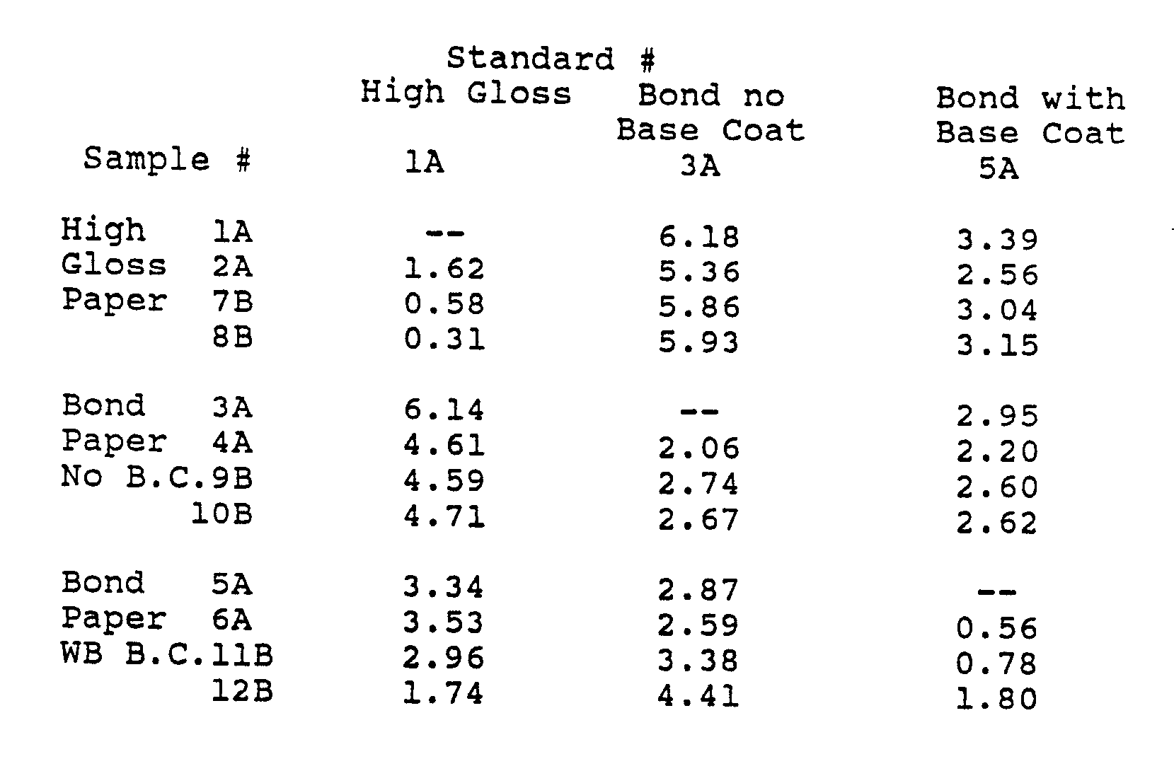
- Delta E color measurements based on the CIE Lab color coordinate system were taken. Three samples were chosen to be standards against which all other samples were compared. The Delta E values are charted below: The above chart taking the -- in Column lA as the standard can be seen that the change in color from the standard in terms of Delta E units is only l.62, .058 and 0.3l which shows that the difference in color from one sample to the next is minimal. For currency type paper, the color change is also very excellent ranging from 0.56 to 0.78 and l.80. The change in color is so small that for these samples it is undetectable by the human eye.
- the yellow pigment In using the yellow pigment blocker in the optically variable ink, the yellow pigment has a tendency to settle above the optically variable pigment since it has a specific gravity of approximately l with respect to the optical variable device flakes which have a specific gravity of approximately 3. In certain applications, however, the best approach in blocking out the blue reflected light at high viewing angles is to print a top coat vehicle containing the yellow pigment layer over the optically variable ink layer.
- the optically variable ink In order to achieve excellent color purity, the optically variable ink must have a good aspect ratio as, for example, at least two-to-one, preferably 5-l0 to one, as pointed out above.
- the optical variable device flakes should not be agglomerated but should be thoroughly dispersed throughout the ink. There should be good overlap of the flakes.
- the ink should have good flow characteristics. If the paper on which the printing is to occur has a rough surface, a subbing layer may be required for currency type applications where high color purity is desired. Alternatively, calendared currency paper may be very desirable to decrease surface roughness.
- the vehicle itself must be durable and must meet press requirements. It must be able to post cure, i.e., it must be cross-linked after the print step. As also pointed out previously, air oxidization, catalyst and UV vehicles are available which cross-link after printing.
- the optically variable device flakes or particles which are provided as a part of the optically variable ink must be inert or alternatively, the flakes must be made oleophobic and hydrophobic or, in other words, they must be encapsulated so they will not react with chemicals such as bases or acids.
- the flakes or particle size should be in the range of 5-l5 microns. This particle size will allow the desired color purity while still allowing for fine line printing. If fine line printing is not desired, then larger size particles may be used, up to l00 microns or so. For coverage the flake or particle loading or flakes should range 30 to 50% by weight for letterpress and offset and l0 to 30% for gravure and Intaglio.
- the curve 22l shows the spectrum of the foil and represents the reflectance of the coating on the polyester web.
- the curves 222 and 223 are of ink made from optically variable flakes made in accordance with the present invention from the foil which is represented by the curve 22l.
- the spectra of the ink were made from samples prepared from 20% by weight of optically variable pigment in Gotham 66908 resin catalyzed with 2.5% by weight Gotham 66909, cured at 200 for four minutes (Gotham Ink and Colors Co., Inc., Long Island City, New York lll0l).
- Curve 222 was obtained from ink prepared from flakes without any grinding (as removed from the web by solvent dissolving the hardcoat/release layer) whereas the other curve 223 was obtained from ink prepared from flakes that had been ground in methanol using ultrasonic dismemberment for l hour (Sonifier Cell Disruptor manufactured by Branson Sonic Power Co. set at a power setting of 9).
- the optical variable flakes in this grinding process were reduced to the size of approximately 5 to 20 microns.
- this grinding process had a very small deleterious effect on the reflectivity of the optically variable flakes.
- there is also very little degradation in the quality, including reflection compared to the reflection received from the foil itself, before it is removed from the web.
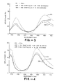
- FIG 4 there is shown another graph giving the reflectance of a gold-to-green shifter of the present invention without the use of a blue-light blocker.
- the graph in Figure 4 has three curves 23l, 232, and 233 in which the curve 23l represents the reflection from the foil on the web, curve 232 represents the reflection from ink utilizing optical variable flakes obtained by removing the optically variable coating from the web by the use of a solvent but without any grinding and the curve 233 represents the reflection obtained from an ink using optical variable flakes which have been ground down to a particle size ranging from 5-20 microns.
- the inks were prepared in the same way as described in connection with the graph in Figure 3.
- the reflectance from the inks is still very good and corresponds very closely to that of the foil itself in that there is little degradation by the grinding of the optically variable flakes to the l0-20 micron size.
- the peak positions in wavelength for the optically variable ink correspond almost exactly to those for the optically variable coating as prepared on the vacuum roll coated web.
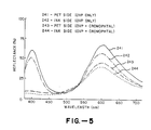
- FIG. 5 there is shown still another graph which shows the reflectance of a gold-to-green ink shifter made in accordance with the present invention with and without the blue-light blocker.
- This ink was deposited onto a polyester clear film substrate.
- Curve 24l shows the reflectance from the PET side with an optical variable ink (OVP) utilizing optically variable flakes therein serving to provide a gold-to-green shifter without a blue-light blocker.
- Curve 242 shows the reflectance from the ink side of the same structure for which the reflectance is shown in curve 24l.
- Curve 243 shows the reflectance from the PET side having a gold-to-green shifter utilizing a blue-light blocker.
- Curve 244 shows the reflectance from the ink side of the gold-to-green shifter shown in curve 243 using a blue-light blocker in yellow pigment.
- the ink utilized for the curves shown in Figure 5 was prepared with three grams of gold-to-green optical variable flakes which had been ultransonically ground to 5-20 micron particle size. The optical variable flakes were then mixed with 7 grams of Del Val Thermoset varnish 5-X-2575 catalyzed with l0% Thermoset catalyst 5-X-2605 and cured at room temperature (Del Val Ink and Color, Inc., l30l Taylor's Lane, Riverton, New Jersey 08077).
- the top two curves 24l and 242 show the reflectance as a function of wavelength when the ink is prepared and cast onto a polyester film and then viewed directly at the coating and also through the polyester film.
- the lower two curves are similar to those curves described above but are for inks prepared with 9.l% (by total weight) of the blue-light blocker (Cromophthal yellow pigment), optically variable flakes and the polymer vehicle.
- the Cromophthal yellow is manufactured by Ciba-Geigy, Glens Falls, New York.
- the curves 243 and 244 clearly show how the blue-light blocker in the form of the yellow pigment effectively blocks the blue light at 400 nanometers.
- an optically variable ink which can serve as a printing ink which can be applied to papers of various types including currency paper.
- This optically variable ink will exhibit two distinct colors, one color when it is viewed straight on or in a direction normal to the surface of the article on which the optically variable ink appears and another color when viewed at a substantial angle, as for example, 45
- the paper which has an optically variable ink printed thereon can be readily examined by the human eye to ascertain whether or not an optically variable ink is present by merely ascertaining the color shift by change in viewing angle.
- Transparent pigments and dyes can be used to block out undesired colors in the spectrum between the two desired colors.
- optically variable ink makes it impossible to duplicate an article with the same colors on color copiers because only one color can be copied or because the optically variable ink reproduces as black rather than as a color or because the color (at normal incidence) is not faithfully reproduced.
- optically variable inks made in accordance with the present invention have numerous applications. They can be utilized for various decorative purposes. They also can be utilized for anti-counterfeiting purposes in currency type papers, as well as security papers.
- optically variable ink is also advantageous in that it can be utilized with existing printing processes without alteration.
Landscapes
- Chemical & Material Sciences (AREA)
- Organic Chemistry (AREA)
- Life Sciences & Earth Sciences (AREA)
- Engineering & Computer Science (AREA)
- Materials Engineering (AREA)
- Wood Science & Technology (AREA)
- Chemical Kinetics & Catalysis (AREA)
- General Chemical & Material Sciences (AREA)
- Geochemistry & Mineralogy (AREA)
- Inks, Pencil-Leads, Or Crayons (AREA)
- Application Of Or Painting With Fluid Materials (AREA)
- Physical Deposition Of Substances That Are Components Of Semiconductor Devices (AREA)
- Non-Silver Salt Photosensitive Materials And Non-Silver Salt Photography (AREA)
- Manufacturing Of Electric Cables (AREA)
- Optical Record Carriers And Manufacture Thereof (AREA)
- Thermal Transfer Or Thermal Recording In General (AREA)
- Printing Methods (AREA)
- Physical Vapour Deposition (AREA)
- Optical Couplings Of Light Guides (AREA)
- Pigments, Carbon Blacks, Or Wood Stains (AREA)
- Polarising Elements (AREA)
- Glass Compositions (AREA)
- Physical Or Chemical Processes And Apparatus (AREA)
- Laminated Bodies (AREA)
- Curing Cements, Concrete, And Artificial Stone (AREA)
- Materials For Medical Uses (AREA)
Abstract
Description
- This invention relates to optical thin film flakes and coatings and inks incorporating the same and a method for making the same and more particularly to optically variable thin film flakes and inks incorporating the same used in anti-counterfeiting applications.
- In the past attempts have been made to make lamellar pigment materials in the manner disclosed in Patent No. 4,l68,986 with the desire to obtain improved specular reflectivity. In U.S. Patent No. 4,434,0l0 there is disclosed an article and method for forming thin film flakes and coatings. There is, however, no disclosure as to how optically variable thin film flakes for incorporation into paints and inks can be produced which incorporate the use of subtractive colorants to block out or minimize undesired colors. There is therefore a need for new and improved optically variable thin film flakes, paints and inks incorporating the same and methods for producing the same.
- Figure l is a flow chart showing the optically variable ink process.
- Figure 2 is a flow chart showing the optically variable ink manufacturing process.
- Figure 3 is a graph showing the reflectance of a magenta-to-green shifter at l0 incidence.
- Figure 4 is a graph showing the reflectance for a gold-to-green shifter at l0 incidence.
- Figure 5 is a graph showing the reflectance of a gold-to-green shifter with and without a blue-light blocking pigment.
- A process for making an optically variable ink (OVI) is shown in Figure l. As shown therein in a converting step 20l, the flexible web is coated with a solvent soluble polymer. The web is formed of a suitable insoluble flexible material using polyethyleneterphthalate (PET), or alternatively, using polymers such as polycarbonates and Kapton. By way of example, a l42 gauge polyester web can be utilized. The web is coated with an acrylic based polymer. One acrylic based polymer found to be satisfactory is one designated as 5l7-l and is manufactured and sold by Thermark Division of Avery International located at Schererville, Indiana. The acrylic based polymer is applied to the web in a suitable manner such as by gravure coating and dried in force air dryers. The polymer coat applied to the web is soluble in at least one solvent. Examples of suitable solvents are acetone and methethylketone. It should be appreciated that other than acrylic polymers, other materials can be utilized for a release layer. For example, instead of using a soluble hardcoat as provided by the acrylic polymer, it is possible to evaporate a thin film coating onto the web which would be soluble in certain liquids. Such a thin layer could be sodium fluoride or sodium chloride which could be dissolved with water. Also it should be appreciated that other release layers which have very low adhesion could be utilized which would permit mechanical removal of the optically variable thin film either by the use of a vacuum or by the use of air jets.
- After the converting step 20l has been carried out, the flexible web can be placed in a vacuum coating chamber for performing the vacuum coating step consisting of depositing an optically variable device (OVD) or optical thin film onto the web as shown by
step 202. The optical variable device can be an optical multilayer structure of the type hereinbefore described. Alternatively, it can be of the type described in co-pending applications EP-A-0170439 and U.S. No.640,l4l, filed on July l3, l984. Optical variable devices of this character can be deposited onto the web in a conventional manner in a vacuum chamber such as by the use of electron beam and resistive heating sources as well as by sputtering. - After the multilayer coating has been deposited on the flexible web, in the vacuum coating process, the soluble polymer layer and the adhering thin film which forms the optically variable device is stripped from the carrier web. This can be accomplished batch wise or in a continuous fashion as shown by
step 203 by passing the web through a bath of a suitable solvent, such as acetone. As the soluble polymer layer is dissolved by the acetone, the thin film is separated from the web mechanically. As the thin film is being removed, it breaks into optical flakes which are of a size on the order of 50 to 200 microns. If a continuous process is being used, the web as it emerges from the solvent, can be engaged by a metal doctor blade to mechanically separate any remaining thin film from the web. - The optical flakes, after they have been removed from the carrier web either in a batch process or a continuous process are then reduced in size as hereinafter described and formulated into an ink as shown by
step 203. Thereafter, the ink can be utilized in various printing processes as shown bystep 204. - A more detailed manufacturing process for making optically variable ink from an optical variable device manufactured in the manner hereinbefore described is shown in Figure 2. As shown therein, the soluble polymer coated web or substrate is prepared in
step 206 as hereinafter described. The coated web is then supplied to a vacuum roll coater in roll form as shown in thestep 207. In the vacuum roll coater, a thin film multilayer coating can be applied over a given width using a single evaporation source with appropriate masking or can be applied to almost the full width of the vacuum roll coater using multiple evaporative sources and appropriate masking. After coating by vacuum evaporation, the web is removed from the roll coater and is slit to remove any defects or unwanted trim (edge non-uniformities). - During this editing process, the spectral properties of the thin film coating can be ascertained and supplied to a computer to provide a running color average of the coating. This makes it possible to modify the color at a later step as hereinafter described in the event that the color is slightly off the desired color for a particular roll. This makes it possible to custom blend to obtain an exact color by either adding a lower or a higher color. By having available a color profile extending along the width and length of the web, it is possible to ascertain the average color of each given roll. By way of example, if average dominant wave length of a roll is, for example, 495 microns and the desired wavelength is 490 microns, this desired wavelength can be obtained by adding some lower wavelength material having a wavelength of 485 microns to achieve the desired 490 microns.
- In the next step 2ll, the thin film is stripped from the web. By way of example, this can be accomplished by taking the rolls and placing the rolls on an unwind roller and having the web pass through a solvent bath and then being taken up by a wind-up roller. The web as it passes through the solvent bath can pass through a series of rollers which are positioned below the level of the solvent bath. If any of the thin film coating still remains on the web as it emerges from the rollers in the bath, this remaining thin film can be removed by a metal doctor blade which scrapes the remaining thin film from the web. The doctor blade typically is positioned on the outside of the roll on the wind-up side so that any adhering flake will fall back into the solvent bath. As explained previously, the flakes in this operation have a tendency to drop off in sizes of approximately 50 to 200 microns.
- The flakes as they fall from the web will fall to the bottom of the tank containing the solvent because they have a much higher specific gravity as, for example, approximately 3 whereas the solvent has a specific gravity of approximately l. After the settling has occurred, the clear solvent liquid above the flakes can be drained from the upper part of the tank containing the solvent. The flakes can then be removed from the tank and used as hereinafter described. Alternatively, the flakes with the remaining solvent can then be filtered and pulled dry as shown by step 2l2 by the use of a vacuum filter of a conventional type. Thereafter, fresh solvent is sprayed over the optically variable flakes forming the filter cake remaining in the filter to remove any last traces of the soluble polymer or other extraneous material from the flakes. The filter cake is then removed from the filter and broken up and then laid out to dry in an air oven at atmospheric pressure at a suitable temperature as, for example, l00 for a period of time ranging from approximately 8 to l0 hours as also shown by step 2l2.
- After the flakes have been dried, they are placed in a suitable solvent solution, such as acetone or methanol and ultrasonically agitated using a conventional ultrasonic agitator as, for example, a Branson sonic dismembrator for a suitable period as, for example, approximately l hour to reduce the particle size to approximately 2-20 microns. Thereafter, the flakes are again filtered to remove the solvent and are air-dryed in an atmospheric oven at a suitable temperature, as for example, 75 overnight or until they are dry.
- In order to reduce the flakes to a still smaller size, as for example, a size ranging from 2 to 5 microns, the dryed flakes are subjected to an air grind in a suitable impact pulverizer such as one manufactured by Garlock Plastomer Products, a division of Colt Industries on Friends Lane, Newton, Pennsylvania l8940. By way of example, a TX laboratory model of the air impact pulverizer has been utilized to grind alumina up to a rate of 8 pounds an hour using a l0 mesh feed to produce particle sizes down to sub micron size, as for example, 0.65 microns. It has been found by using this air impact pulverizer, 2 to 5 micron size can be readily achieved without destroying the color characteristics of the flakes. It should be appreciated that other grinding techniques can be utilized. However, care must be taken so that the grinding will not destroy the color characteristics of the flakes.
- A particularly attractive feature of the air impact process for producing the small size optically variable thin film flakes is that an aspect ratio of at least 2 to l can be achieved, and a fairly narrow particle size distribution can be obtained. The aspect ratio is ascertained by taking the largest dimension of a surface of the flake parallel to the planes of the layers of the thin film and a surface (the thickness) perpendicular to the planes of the layers. In addition, the air impact process eliminates the need for additional solvent dispersal and solvent removal steps.
- After the flakes have been sized, they can be blended with other flakes to achieve the exact color desired by adding flakes having a higher or lower wavelength to achieve the desired result. This sizing and blending process is represented by step 2l3 in Figure 2.
- The sized and blended flakes are then introduced into an ink polymer vehicle which consists of a main vehicle with various additives in Step 2l3.
- It should be appreciated that various types of ink vehicle systems can be utilized. For example, ultra-violet cured solvent systems, oxidative systems and catalytic systems can be utilized. One type of ink system which has been found to be satisfactory for use with the flakes is a catalytic system supplied by Dal Val Ink and Color, Inc. at 3l0l Taylor's Lane, Riverton, New Jersey 08077 under the designations of 5-X-2575 and 5-X-2605. Another one found to be suitable is an epoxy based gravure ink supplied by Gotham Ink and Color Inc. of Long Island City, New York under Nos. 66908 and 66909.
- In connection with optically variable inks, it may be desirable to add transparent dyes or pigments to the ink formulation to operate in a subtractive mode to modify the colors and/or to block unwanted colors. For example, in the case of a gold-to-green shifter, the addition of yellow dyes or yellow transparent pigments blocks the blue reflected light at large viewing angles. Blocking pigments can be added as a separate overprint ink layer or can be mixed directly into the optically variable ink, as shown by step 2l4. By way of example, if yellow is the color to be utilized, various transparent yellow blocking pigments are available. For example, cromophtal yellow 3G (C. I. pigment yellow 93) can be obtained from the Pigments Department of Ciba-Geigy of Ardsley, New York l0502. Sunset Gold HR Transparent l28l (C. I. pigment yellow 83) can be obtained from Harshaw Company and Diarylide Yellow Toner AA0A-Transparent l275 also can be obtained from Harshaw. ll-l405 Novoperm yellow HR Extra Transparent (C. I. pigment yellow 83) can be obtained from American Hoechst Corporation of Coventry, Rhode lsland, as well as ll-l424 Novoperm yellow RH-02 and ll-l400 Novoperm yellow HR.
- The yellow pigments are typically supplied in a yellow powder of a sub-micron size and are introduced into the ink as it is being mixed and milled to a percentage ranging from 2 to 30% by weight of the resulting optically variable ink. However, in order to achieve a brighter color it is desirable to utilize a lower percentage by weight of color, as for example, approximately l5%. The mixing and milling operation shown by step 2l3 is carried out to obtain good dispersion of the added pigment. It also causes good dispersion of the flakes which have been added to the paint vehicle. The mixed paint can then be packaged into desirable containers and shipped to the user as shown by step 2l6.
- The optically variable ink produced in accordance with the present invention can be utilized with various conventional printing presses without modification of the presses. For example, the optically variable ink can be utilized in various printing processes, such as lithographic printing, letterpress printing, intaglio printing, gravure printing, screen printing, ink jet printing, and by electrostatic printing. Since the optically variable printing ink can be utilized with printing processes providing high resolution such as Intaglio, lithographic and relief printing, it can be utilized for producing security-type documents. As it is well known to those skilled in the art, the film thickness after it is applied as a wet film on full solid coated paper can have the following thicknesses:

- From the above it can be seen that the gravure or the screen ink film thicknesses are greater and thus gives greater color saturation than with the thinner ink films.
- The aspect ratio is important in that it helps to ensure that the flakes will land either on their top and bottom sides and not on their ends. It can be appreciated if the flakes fall on their ends, that there would be no color shift from the flake. It is important that the optical variable device be symmetrical so that no matter which side the flake lands on, it still will give a color shift. In other words, the color will be maintained. Thus it certainly is desirable not to have a one-to-one aspect ratio but rather be at least two-to-one or three-to-one. Since the total thickness of the optically variable thin film is approximately .9 microns, the 2 micron dimension is approximately the smallest dimension desired for the flakes. By utilizing an aspect ratio of at least 2 to l and greater, preferably 5-l0, to l, gives assurance that a major proportion of the flakes will land in the ink vehicle with an orientation such that the surfaces providing the color of the flakes will be facing upwardly since the thin film coating is symmetrical and those surfaces have the larger dimensions.
- It should be appreciated that with the different wet film thicknesses it is easier to print with thicker layers of material and in addition, this makes it possible to utilize a smaller percentage of optically variable device flakes in the printing media. Thus with gravure it is possible to utilize only 25% by weight of optical variable device flakes whereas with letter press printing and other thinner coatings it is necessary to increase the percentage of optical variable device flakes to 45 to 50% by weight.
- If a color shift between two colors with change of viewing angle such as a typical gold-to-green design is desired for an optically variable ink for anti-counterfeiting applications, a five layer symmetrical design of the type MDMDM where M is a metal layer and D is a dielectric layer. The materials used for M and D can be chosen from a wide variety of substances.
- It has been possible to achieve very good color control with optically variable inks. To ascertain this optical variable inks were air brushed onto three different surfaces outlined below.
- 1. Hi-Gloss Paper
- 2. Bond Paper
- 3. Bond Paper With Water Base Base Coat
- Delta E color measurements based on the CIE Lab color coordinate system were taken. Three samples were chosen to be standards against which all other samples were compared. The Delta E values are charted below:
- In using the yellow pigment blocker in the optically variable ink, the yellow pigment has a tendency to settle above the optically variable pigment since it has a specific gravity of approximately l with respect to the optical variable device flakes which have a specific gravity of approximately 3. In certain applications, however, the best approach in blocking out the blue reflected light at high viewing angles is to print a top coat vehicle containing the yellow pigment layer over the optically variable ink layer.
- In order to achieve excellent color purity, the optically variable ink must have a good aspect ratio as, for example, at least two-to-one, preferably 5-l0 to one, as pointed out above. The optical variable device flakes should not be agglomerated but should be thoroughly dispersed throughout the ink. There should be good overlap of the flakes. The ink should have good flow characteristics. If the paper on which the printing is to occur has a rough surface, a subbing layer may be required for currency type applications where high color purity is desired. Alternatively, calendared currency paper may be very desirable to decrease surface roughness.
- As also pointed out previously to obtain good optically variable ink durability, the vehicle itself must be durable and must meet press requirements. It must be able to post cure, i.e., it must be cross-linked after the print step. As also pointed out previously, air oxidization, catalyst and UV vehicles are available which cross-link after printing. The optically variable device flakes or particles which are provided as a part of the optically variable ink must be inert or alternatively, the flakes must be made oleophobic and hydrophobic or, in other words, they must be encapsulated so they will not react with chemicals such as bases or acids.
- For a good quality gravure or Intaglio ink, the flakes or particle size should be in the range of 5-l5 microns. This particle size will allow the desired color purity while still allowing for fine line printing. If fine line printing is not desired, then larger size particles may be used, up to l00 microns or so. For coverage the flake or particle loading or flakes should range 30 to 50% by weight for letterpress and offset and l0 to 30% for gravure and Intaglio.
- In the graph in Figure 3 there is shown the reflectance which can be obtained with a magenta-to-green shifter of the present invention. The curve 22l shows the spectrum of the foil and represents the reflectance of the coating on the polyester web. The
curves Curve 222 was obtained from ink prepared from flakes without any grinding (as removed from the web by solvent dissolving the hardcoat/release layer) whereas theother curve 223 was obtained from ink prepared from flakes that had been ground in methanol using ultrasonic dismemberment for l hour (Sonifier Cell Disruptor manufactured by Branson Sonic Power Co. set at a power setting of 9). The optical variable flakes in this grinding process were reduced to the size of approximately 5 to 20 microns. As can be seen from thecurve 223, this grinding process had a very small deleterious effect on the reflectivity of the optically variable flakes. In addition, it can be seen that there is also very little degradation in the quality, including reflection, compared to the reflection received from the foil itself, before it is removed from the web. - In Figure 4, there is shown another graph giving the reflectance of a gold-to-green shifter of the present invention without the use of a blue-light blocker. As in the graph in Figure 3, the graph in Figure 4 has three
curves curve 232 represents the reflection from ink utilizing optical variable flakes obtained by removing the optically variable coating from the web by the use of a solvent but without any grinding and thecurve 233 represents the reflection obtained from an ink using optical variable flakes which have been ground down to a particle size ranging from 5-20 microns. The inks were prepared in the same way as described in connection with the graph in Figure 3. Here again it can be seen that the reflectance from the inks is still very good and corresponds very closely to that of the foil itself in that there is little degradation by the grinding of the optically variable flakes to the l0-20 micron size. Note that the peak positions in wavelength for the optically variable ink correspond almost exactly to those for the optically variable coating as prepared on the vacuum roll coated web. - In Figure 5 there is shown still another graph which shows the reflectance of a gold-to-green ink shifter made in accordance with the present invention with and without the blue-light blocker. This ink was deposited onto a polyester clear film substrate. Curve 24l shows the reflectance from the PET side with an optical variable ink (OVP) utilizing optically variable flakes therein serving to provide a gold-to-green shifter without a blue-light blocker.
Curve 242 shows the reflectance from the ink side of the same structure for which the reflectance is shown in curve 24l.Curve 243 shows the reflectance from the PET side having a gold-to-green shifter utilizing a blue-light blocker.Curve 244 shows the reflectance from the ink side of the gold-to-green shifter shown incurve 243 using a blue-light blocker in yellow pigment. The ink utilized for the curves shown in Figure 5 was prepared with three grams of gold-to-green optical variable flakes which had been ultransonically ground to 5-20 micron particle size. The optical variable flakes were then mixed with 7 grams of Del Val Thermoset varnish 5-X-2575 catalyzed with l0% Thermoset catalyst 5-X-2605 and cured at room temperature (Del Val Ink and Color, Inc., l30l Taylor's Lane, Riverton, New Jersey 08077). The top twocurves 24l and 242 show the reflectance as a function of wavelength when the ink is prepared and cast onto a polyester film and then viewed directly at the coating and also through the polyester film. The lower two curves are similar to those curves described above but are for inks prepared with 9.l% (by total weight) of the blue-light blocker (Cromophthal yellow pigment), optically variable flakes and the polymer vehicle. The Cromophthal yellow is manufactured by Ciba-Geigy, Glens Falls, New York. Thecurves - From the foregoing it can be seen that there has been provided an optically variable ink which can serve as a printing ink which can be applied to papers of various types including currency paper. This optically variable ink will exhibit two distinct colors, one color when it is viewed straight on or in a direction normal to the surface of the article on which the optically variable ink appears and another color when viewed at a substantial angle, as for example, 45 Thus the paper which has an optically variable ink printed thereon can be readily examined by the human eye to ascertain whether or not an optically variable ink is present by merely ascertaining the color shift by change in viewing angle. Transparent pigments and dyes can be used to block out undesired colors in the spectrum between the two desired colors. They also can be used to block out undesired high angle colors. Further, these additives can be used to modify the colors wanted at the various viewing angles. In addition, the use of the optically variable ink makes it impossible to duplicate an article with the same colors on color copiers because only one color can be copied or because the optically variable ink reproduces as black rather than as a color or because the color (at normal incidence) is not faithfully reproduced.
- Therefore it can be seen that optically variable inks made in accordance with the present invention have numerous applications. They can be utilized for various decorative purposes. They also can be utilized for anti-counterfeiting purposes in currency type papers, as well as security papers.
- The optically variable ink is also advantageous in that it can be utilized with existing printing processes without alteration.
Claims (16)
Priority Applications (1)
| Application Number | Priority Date | Filing Date | Title |
|---|---|---|---|
| AT86309838T ATE76888T1 (en) | 1985-12-23 | 1986-12-16 | THIN FILM OPTICAL SHELLS, REPLICA OPTICAL COATING, AND COATINGS AND INKS INCLUDING THEM AND METHODS THEREOF. |
Applications Claiming Priority (2)
| Application Number | Priority Date | Filing Date | Title |
|---|---|---|---|
| US81281485A | 1985-12-23 | 1985-12-23 | |
| US812814 | 1985-12-23 |
Publications (3)
| Publication Number | Publication Date |
|---|---|
| EP0227423A2 true EP0227423A2 (en) | 1987-07-01 |
| EP0227423A3 EP0227423A3 (en) | 1988-12-07 |
| EP0227423B1 EP0227423B1 (en) | 1992-06-03 |
Family
ID=25210705
Family Applications (1)
| Application Number | Title | Priority Date | Filing Date |
|---|---|---|---|
| EP86309838A Expired - Lifetime EP0227423B1 (en) | 1985-12-23 | 1986-12-16 | Optical thin film flakes, replicated optical coatings and coatings and inks incorporating the same and method |
Country Status (10)
| Country | Link |
|---|---|
| EP (1) | EP0227423B1 (en) |
| JP (1) | JPS62260875A (en) |
| AT (1) | ATE76888T1 (en) |
| AU (2) | AU606321B2 (en) |
| CA (1) | CA1315448C (en) |
| DE (1) | DE3685566T2 (en) |
| DK (3) | DK628586A (en) |
| ES (1) | ES2031454T3 (en) |
| GR (1) | GR3005337T3 (en) |
| NZ (1) | NZ218573A (en) |
Cited By (48)
| Publication number | Priority date | Publication date | Assignee | Title |
|---|---|---|---|---|
| US4837061A (en) * | 1987-08-10 | 1989-06-06 | Alcan International Limited | Tamper-evident structures |
| US4994314A (en) * | 1989-02-03 | 1991-02-19 | Alcan International Limited | Color change devices incorporating thin anodic films |
| US5015318A (en) * | 1987-08-10 | 1991-05-14 | Alcan International Limited | Method of making tamper-evident structures |
| US5055150A (en) * | 1989-02-03 | 1991-10-08 | Alcan International Limited | Process and apparatus for producing coated polymer sheets having oxygen and moisture barrier properties and coated polymer sheets thus produced |
| US5062928A (en) * | 1990-04-17 | 1991-11-05 | Alcan International Limited | Process for producing color change devices incorporating latent indicia and the resulting devices |
| US5156720A (en) * | 1989-02-02 | 1992-10-20 | Alcan International Limited | Process for producing released vapor deposited films and product produced thereby |
| EP0619192A1 (en) * | 1993-04-05 | 1994-10-12 | De La Rue Giori S.A. | Printing plate |
| US5492370A (en) * | 1991-03-22 | 1996-02-20 | De La Rue Holographics Ltd. | Decorative article |
| EP0730753A4 (en) * | 1993-11-23 | 1997-02-26 | Commw Scient Ind Res Org | Diffractive indicia for a surface |
| WO2000024946A1 (en) * | 1998-10-23 | 2000-05-04 | Avery Dennison Corporation | Process for making metal flakes |
| WO2000043565A1 (en) * | 1999-01-20 | 2000-07-27 | Hilmar Weinert | Method and device for producing colored pigments |
| US6270840B1 (en) | 1998-09-28 | 2001-08-07 | Weinert Vakuum Verfahrenstechnik Gmbh | Apparatus and method for producing plane-parallel flakes |
| US6428846B2 (en) | 1996-08-30 | 2002-08-06 | Eckart-Werke Standard Bronzepulver-Werke Carl Eckart & Co. | Corrosion-stable aluminum pigments and process for the production thereof |
| WO2003046245A3 (en) * | 2001-11-29 | 2004-02-12 | Avery Dennison Corp | Process for making angstrom scale and high aspect functional platelets |
| US6863851B2 (en) | 1998-10-23 | 2005-03-08 | Avery Dennison Corporation | Process for making angstrom scale and high aspect functional platelets |
| EP1630285A2 (en) | 2004-08-27 | 2006-03-01 | De La Rue International Limited | A method of manufacturing a fibrous substrate incorporating an elongate element |
| WO2006021528A2 (en) | 2004-08-23 | 2006-03-02 | Ciba Specialty Chemicals Holding Inc. | Process for preparing flake-form pigments based on aluminium and on sioz (z=0 . 7-2.0) |
| US7040663B1 (en) | 1999-02-23 | 2006-05-09 | Giesecke & Devrient, Gmbh | Value document |
| EP1669213A1 (en) | 2004-12-09 | 2006-06-14 | Sicpa Holding S.A. | Security element having a viewing-angle dependent aspect |
| WO2006066131A1 (en) * | 2004-12-17 | 2006-06-22 | Cabot Corporation | Inkjet inks comprising multi-layer pigments |
| WO2006117271A1 (en) | 2005-05-04 | 2006-11-09 | Sicpa Holding S.A. | Black-to-color shifting security element |
| EP1880866A1 (en) | 2006-07-19 | 2008-01-23 | Sicpa Holding S.A. | Oriented image coating on transparent substrate |
| WO2007140484A3 (en) * | 2006-05-31 | 2008-10-02 | Cabot Corp | Colored reflective features and inks and processes for making them |
| DE112006003410T5 (en) | 2005-12-20 | 2009-01-02 | De La Rue International Ltd., Basingstoke | Improvements in methods of making security substrates |
| WO2009053391A2 (en) | 2007-10-26 | 2009-04-30 | Basf Se | Security element |
| CN101337477B (en) * | 2007-07-06 | 2011-01-12 | 比亚迪股份有限公司 | A kind of workpiece surface coating method |
| WO2011010041A2 (en) | 2009-07-20 | 2011-01-27 | L'oreal | Emulsion containing a bismuth oxychloride dispersion |
| WO2011012520A2 (en) | 2009-07-28 | 2011-02-03 | Sicpa Holding Sa | Transfer foil comprising optically variable magnetic pigment, method of making, use of transfer foil, and article or document comprising such |
| WO2011067807A1 (en) | 2009-12-02 | 2011-06-09 | L'oreal | Cosmetic composition containing fusiform particles for cosmetic use |
| DE102010047250A1 (en) | 2009-12-04 | 2011-06-09 | Giesecke & Devrient Gmbh | Security element, value document with such a security element and manufacturing method of a security element |
| WO2012001808A1 (en) | 2010-07-01 | 2012-01-05 | トヨタ自動車株式会社 | Method for producing ceramic laminate, and ceramic laminate produced by the production method |
| WO2012042570A1 (en) | 2010-09-29 | 2012-04-05 | L'oreal | A cosmetic method for hiding skin imperfections |
| US8246735B2 (en) | 2006-05-12 | 2012-08-21 | Sicpa Holding Sa | Coating composition for producing magnetically induced images |
| EP2573739A1 (en) | 2011-09-26 | 2013-03-27 | Sicpa Holding Sa | Optically variable entity authenticating device and method |
| WO2013045082A1 (en) | 2011-09-26 | 2013-04-04 | Sicpa Holding Sa | Optically variable entity authenticating device and method |
| EP1299250B2 (en) † | 2000-07-10 | 2013-09-25 | De La Rue International Limited | Method of providing an image on a substrate, and an ink for use therein |
| WO2013143829A2 (en) | 2012-03-27 | 2013-10-03 | Sicpa Holding Sa | Multilayer flake with high level of coding |
| US8557403B2 (en) | 2006-10-17 | 2013-10-15 | Sicpa Holding S.A. | Method and means for magnetically transferring indicia to a coating composition applied on a substrate |
| WO2014072172A1 (en) | 2012-11-09 | 2014-05-15 | Sicpa Holding Sa | Irreversibly magnetically induced images or patterns |
| WO2014203913A1 (en) | 2013-06-18 | 2014-12-24 | L'oreal | Cosmetic composition |
| WO2015083099A1 (en) | 2013-12-03 | 2015-06-11 | Arjowiggins Security | Security structure |
| US9297941B2 (en) | 2011-07-21 | 2016-03-29 | Giesecke & Deverient Gmbh | Optically variable element, in particular security element |
| US9827802B2 (en) | 2009-12-04 | 2017-11-28 | Giesecke+Devrient Currency Technology Gmbh | Security element, value document comprising such a security element, and method for producing such a security element |
| US9892586B2 (en) | 2013-10-11 | 2018-02-13 | Sicpa Holding Sa | Hand-held device and method for authenticating a marking |
| EP3431304A1 (en) | 2017-07-18 | 2019-01-23 | Agfa-Gevaert | Method of providing an ovd on a security document by laser marking |
| EP3489030A1 (en) | 2017-11-27 | 2019-05-29 | Agfa-Gevaert | Method of providing a security element on a security document by laser marking |
| EP3540014A1 (en) * | 2018-03-14 | 2019-09-18 | Viavi Solutions Inc. | Solvent-less method to manufacture thin film devices |
| EP3842253A1 (en) | 2019-12-23 | 2021-06-30 | HID Global Rastede GmbH | Uv curable and heat sealable ink |
Families Citing this family (19)
| Publication number | Priority date | Publication date | Assignee | Title |
|---|---|---|---|---|
| US2580145A (en) * | 1949-06-06 | 1951-12-25 | Godfrey L White | Attachment for controlling weeds in cotton |
| US5766738A (en) * | 1979-12-28 | 1998-06-16 | Flex Products, Inc. | Paired optically variable article with paired optically variable structures and ink, paint and foil incorporating the same and method |
| EP0766103B1 (en) * | 1993-08-06 | 2001-05-23 | Commonwealth Scientific And Industrial Research Organisation | A diffractive device |
| AU674805B2 (en) * | 1993-11-23 | 1997-01-09 | Commonwealth Scientific And Industrial Research Organisation | Diffractive indicia for a surface |
| AU732595B2 (en) * | 1996-08-23 | 2001-04-26 | Katsuto Nakatsuka | Rheological fluid |
| EP0978373B1 (en) * | 1998-08-06 | 2011-10-12 | Sicpa Holding Sa | Inorganic sheet for making pigments |
| US6761959B1 (en) * | 1999-07-08 | 2004-07-13 | Flex Products, Inc. | Diffractive surfaces with color shifting backgrounds |
| JP2003520986A (en) * | 2000-01-21 | 2003-07-08 | フレックス プロダクツ インコーポレイテッド | Optical modulation security device |
| DE10004888A1 (en) | 2000-02-04 | 2001-08-09 | Eckart Standard Bronzepulver | Luster pigment and process for its manufacture |
| US20020160194A1 (en) * | 2001-04-27 | 2002-10-31 | Flex Products, Inc. | Multi-layered magnetic pigments and foils |
| US7588817B2 (en) * | 2005-03-11 | 2009-09-15 | Jds Uniphase Corporation | Engraved optically variable image device |
| DE102010006173A1 (en) | 2010-01-29 | 2011-08-04 | Giesecke & Devrient GmbH, 81677 | Security element with extended color shift effect and thermochromic additional function |
| JP5781880B2 (en) * | 2010-09-29 | 2015-09-24 | トヨタ モーター エンジニアリング アンド マニュファクチャリング ノース アメリカ,インコーポレイティド | Structural color with UV reflectivity via layer-by-layer spray method |
| US8322636B2 (en) * | 2010-12-15 | 2012-12-04 | Toyota Motor Engineering & Manufacturing North America, Inc. | Production of multilayered thin film particles |
| DE102016004424A1 (en) | 2016-04-12 | 2017-10-12 | Giesecke+Devrient Currency Technology Gmbh | Laser coating with effect pigments |
| DE102016014205A1 (en) | 2016-11-29 | 2018-05-30 | Giesecke+Devrient Currency Technology Gmbh | Screen printing of effect colors on value documents |
| DE102019005456A1 (en) | 2019-08-02 | 2021-02-04 | Giesecke+Devrient Currency Technology Gmbh | Process for producing effect pigments |
| DE102021000478A1 (en) | 2021-02-01 | 2022-08-04 | Giesecke+Devrient Currency Technology Gmbh | Mask exposure process, transparent conductive metallization and pigment |
| DE102022125862A1 (en) | 2022-10-06 | 2024-04-11 | Giesecke+Devrient Currency Technology Gmbh | Security element with light-refracting structures and colour change |
Family Cites Families (6)
| Publication number | Priority date | Publication date | Assignee | Title |
|---|---|---|---|---|
| NL131827C (en) * | 1961-02-06 | |||
| NL131828C (en) * | 1961-05-04 | |||
| NL280256A (en) * | 1961-06-28 | |||
| US4168986A (en) * | 1978-07-03 | 1979-09-25 | Polaroid Corporation | Method for preparing lamellar pigments |
| US4434010A (en) * | 1979-12-28 | 1984-02-28 | Optical Coating Laboratory, Inc. | Article and method for forming thin film flakes and coatings |
| US4705356A (en) * | 1984-07-13 | 1987-11-10 | Optical Coating Laboratory, Inc. | Thin film optical variable article having substantial color shift with angle and method |
-
1986
- 1986-12-09 NZ NZ218573A patent/NZ218573A/en unknown
- 1986-12-12 AU AU66451/86A patent/AU606321B2/en not_active Ceased
- 1986-12-16 DE DE8686309838T patent/DE3685566T2/en not_active Expired - Lifetime
- 1986-12-16 AT AT86309838T patent/ATE76888T1/en not_active IP Right Cessation
- 1986-12-16 ES ES198686309838T patent/ES2031454T3/en not_active Expired - Lifetime
- 1986-12-16 EP EP86309838A patent/EP0227423B1/en not_active Expired - Lifetime
- 1986-12-22 CA CA000525988A patent/CA1315448C/en not_active Expired - Lifetime
- 1986-12-23 DK DK628586A patent/DK628586A/en not_active Application Discontinuation
- 1986-12-23 JP JP61307553A patent/JPS62260875A/en active Granted
-
1991
- 1991-04-29 AU AU76113/91A patent/AU637900B2/en not_active Withdrawn - After Issue
-
1992
- 1992-08-04 GR GR920401675T patent/GR3005337T3/el unknown
-
1993
- 1993-11-12 DK DK931283A patent/DK128393D0/en not_active Application Discontinuation
-
1995
- 1995-04-03 DK DK036695A patent/DK36695A/en not_active Application Discontinuation
Cited By (73)
| Publication number | Priority date | Publication date | Assignee | Title |
|---|---|---|---|---|
| US5015318A (en) * | 1987-08-10 | 1991-05-14 | Alcan International Limited | Method of making tamper-evident structures |
| US4837061A (en) * | 1987-08-10 | 1989-06-06 | Alcan International Limited | Tamper-evident structures |
| US5156720A (en) * | 1989-02-02 | 1992-10-20 | Alcan International Limited | Process for producing released vapor deposited films and product produced thereby |
| US4994314A (en) * | 1989-02-03 | 1991-02-19 | Alcan International Limited | Color change devices incorporating thin anodic films |
| US5055150A (en) * | 1989-02-03 | 1991-10-08 | Alcan International Limited | Process and apparatus for producing coated polymer sheets having oxygen and moisture barrier properties and coated polymer sheets thus produced |
| US5062928A (en) * | 1990-04-17 | 1991-11-05 | Alcan International Limited | Process for producing color change devices incorporating latent indicia and the resulting devices |
| US5492370A (en) * | 1991-03-22 | 1996-02-20 | De La Rue Holographics Ltd. | Decorative article |
| EP0619192A1 (en) * | 1993-04-05 | 1994-10-12 | De La Rue Giori S.A. | Printing plate |
| EP0730753A4 (en) * | 1993-11-23 | 1997-02-26 | Commw Scient Ind Res Org | Diffractive indicia for a surface |
| US6428846B2 (en) | 1996-08-30 | 2002-08-06 | Eckart-Werke Standard Bronzepulver-Werke Carl Eckart & Co. | Corrosion-stable aluminum pigments and process for the production thereof |
| US6270840B1 (en) | 1998-09-28 | 2001-08-07 | Weinert Vakuum Verfahrenstechnik Gmbh | Apparatus and method for producing plane-parallel flakes |
| US6398999B1 (en) | 1998-10-23 | 2002-06-04 | Avery Dennison Corporation | Process for making high aspect ratio reflective metal flakes |
| WO2000024946A1 (en) * | 1998-10-23 | 2000-05-04 | Avery Dennison Corporation | Process for making metal flakes |
| US7820088B2 (en) | 1998-10-23 | 2010-10-26 | Avery Dennison Corporation | Process for making angstrom scale and high aspect functional platelets |
| US6863851B2 (en) | 1998-10-23 | 2005-03-08 | Avery Dennison Corporation | Process for making angstrom scale and high aspect functional platelets |
| WO2000043565A1 (en) * | 1999-01-20 | 2000-07-27 | Hilmar Weinert | Method and device for producing colored pigments |
| US7040663B1 (en) | 1999-02-23 | 2006-05-09 | Giesecke & Devrient, Gmbh | Value document |
| EP1299250B2 (en) † | 2000-07-10 | 2013-09-25 | De La Rue International Limited | Method of providing an image on a substrate, and an ink for use therein |
| WO2003046245A3 (en) * | 2001-11-29 | 2004-02-12 | Avery Dennison Corp | Process for making angstrom scale and high aspect functional platelets |
| WO2006021528A2 (en) | 2004-08-23 | 2006-03-02 | Ciba Specialty Chemicals Holding Inc. | Process for preparing flake-form pigments based on aluminium and on sioz (z=0 . 7-2.0) |
| EP1630285A2 (en) | 2004-08-27 | 2006-03-01 | De La Rue International Limited | A method of manufacturing a fibrous substrate incorporating an elongate element |
| EP1669213A1 (en) | 2004-12-09 | 2006-06-14 | Sicpa Holding S.A. | Security element having a viewing-angle dependent aspect |
| WO2006061301A1 (en) | 2004-12-09 | 2006-06-15 | Sicpa Holding S.A. | Security element having a viewing-angle dependent aspect |
| US8211531B2 (en) | 2004-12-09 | 2012-07-03 | Sicpa Holding Sa | Security element having a viewing-angel dependent aspect |
| JP2008529823A (en) * | 2004-12-09 | 2008-08-07 | シクパ・ホールディング・ソシエテ・アノニム | Security element with a viewing angle dependent appearance |
| US7651557B2 (en) | 2004-12-17 | 2010-01-26 | Cabot Corporation | Inkjet inks comprising multi-layer pigments |
| WO2006066131A1 (en) * | 2004-12-17 | 2006-06-22 | Cabot Corporation | Inkjet inks comprising multi-layer pigments |
| WO2006117271A1 (en) | 2005-05-04 | 2006-11-09 | Sicpa Holding S.A. | Black-to-color shifting security element |
| US8147932B2 (en) | 2005-05-04 | 2012-04-03 | Sicpa Holding Sa | Black-to-color shifting security element |
| DE112006003410T5 (en) | 2005-12-20 | 2009-01-02 | De La Rue International Ltd., Basingstoke | Improvements in methods of making security substrates |
| US8303700B1 (en) | 2006-05-12 | 2012-11-06 | Sicpa Holding Sa | Coating composition for producing magnetically induced |
| US8246735B2 (en) | 2006-05-12 | 2012-08-21 | Sicpa Holding Sa | Coating composition for producing magnetically induced images |
| WO2007140484A3 (en) * | 2006-05-31 | 2008-10-02 | Cabot Corp | Colored reflective features and inks and processes for making them |
| EP1880866A1 (en) | 2006-07-19 | 2008-01-23 | Sicpa Holding S.A. | Oriented image coating on transparent substrate |
| US8696031B2 (en) | 2006-07-19 | 2014-04-15 | Sicpa Holding Sa | Oriented image coating on transparent substrate |
| US8557403B2 (en) | 2006-10-17 | 2013-10-15 | Sicpa Holding S.A. | Method and means for magnetically transferring indicia to a coating composition applied on a substrate |
| CN101337477B (en) * | 2007-07-06 | 2011-01-12 | 比亚迪股份有限公司 | A kind of workpiece surface coating method |
| WO2009053391A3 (en) * | 2007-10-26 | 2009-12-23 | Basf Se | Security element |
| WO2009053391A2 (en) | 2007-10-26 | 2009-04-30 | Basf Se | Security element |
| EP2826460A1 (en) | 2009-07-20 | 2015-01-21 | L'oreal | Emulsion containing a dispersion of bismuth oxychloride |
| EP2826459A1 (en) | 2009-07-20 | 2015-01-21 | L'oreal | Emulsion containing a dispersion of bismuth oxychloride |
| WO2011010041A2 (en) | 2009-07-20 | 2011-01-27 | L'oreal | Emulsion containing a bismuth oxychloride dispersion |
| WO2011012520A2 (en) | 2009-07-28 | 2011-02-03 | Sicpa Holding Sa | Transfer foil comprising optically variable magnetic pigment, method of making, use of transfer foil, and article or document comprising such |
| WO2011067807A1 (en) | 2009-12-02 | 2011-06-09 | L'oreal | Cosmetic composition containing fusiform particles for cosmetic use |
| WO2011066991A2 (en) | 2009-12-04 | 2011-06-09 | Giesecke & Devrient Gmbh | Security element, value document comprising such a security element and method for producing such a security element |
| DE102010047250A1 (en) | 2009-12-04 | 2011-06-09 | Giesecke & Devrient Gmbh | Security element, value document with such a security element and manufacturing method of a security element |
| EP4512631A2 (en) | 2009-12-04 | 2025-02-26 | Giesecke+Devrient Currency Technology GmbH | Security element, valuable document having such a security element, and method for producing a security element |
| EP3851290A1 (en) | 2009-12-04 | 2021-07-21 | Giesecke+Devrient Currency Technology GmbH | Security element, valuable document comprising such a security element and method for producing such a security element |
| US10525758B2 (en) | 2009-12-04 | 2020-01-07 | Giesecke+Devrient Currency Technology Gmbh | Security element, value document comprising such a security element, and method for producing such a security element |
| US9827802B2 (en) | 2009-12-04 | 2017-11-28 | Giesecke+Devrient Currency Technology Gmbh | Security element, value document comprising such a security element, and method for producing such a security element |
| EP3216620A1 (en) | 2009-12-04 | 2017-09-13 | Giesecke+Devrient Currency Technology GmbH | Security element, valuable document comprising such a security element and method for producing such a security element |
| US9176266B2 (en) | 2009-12-04 | 2015-11-03 | Giesecke & Devrient Gmbh | Security element, value document comprising such a security element and method for producing such a security element |
| WO2012001808A1 (en) | 2010-07-01 | 2012-01-05 | トヨタ自動車株式会社 | Method for producing ceramic laminate, and ceramic laminate produced by the production method |
| WO2012042570A1 (en) | 2010-09-29 | 2012-04-05 | L'oreal | A cosmetic method for hiding skin imperfections |
| US9297941B2 (en) | 2011-07-21 | 2016-03-29 | Giesecke & Deverient Gmbh | Optically variable element, in particular security element |
| EP2573739A1 (en) | 2011-09-26 | 2013-03-27 | Sicpa Holding Sa | Optically variable entity authenticating device and method |
| US9228901B2 (en) | 2011-09-26 | 2016-01-05 | Sicpa Holding Sa | Optically variable entity authenticating device and method |
| WO2013045082A1 (en) | 2011-09-26 | 2013-04-04 | Sicpa Holding Sa | Optically variable entity authenticating device and method |
| WO2013143829A2 (en) | 2012-03-27 | 2013-10-03 | Sicpa Holding Sa | Multilayer flake with high level of coding |
| US8864037B2 (en) | 2012-03-27 | 2014-10-21 | Sicpa Holding Sa | Multilayer flake with high level of coding |
| US9724957B2 (en) | 2012-11-09 | 2017-08-08 | Sicpa Holding Sa | Irreversibly magnetically induced images or patterns |
| WO2014072172A1 (en) | 2012-11-09 | 2014-05-15 | Sicpa Holding Sa | Irreversibly magnetically induced images or patterns |
| WO2014203913A1 (en) | 2013-06-18 | 2014-12-24 | L'oreal | Cosmetic composition |
| US9892586B2 (en) | 2013-10-11 | 2018-02-13 | Sicpa Holding Sa | Hand-held device and method for authenticating a marking |
| WO2015083099A1 (en) | 2013-12-03 | 2015-06-11 | Arjowiggins Security | Security structure |
| EP3431304A1 (en) | 2017-07-18 | 2019-01-23 | Agfa-Gevaert | Method of providing an ovd on a security document by laser marking |
| WO2019016007A1 (en) | 2017-07-18 | 2019-01-24 | Agfa-Gevaert Nv | Method of providing an ovd on a security document by laser marking |
| EP3489030A1 (en) | 2017-11-27 | 2019-05-29 | Agfa-Gevaert | Method of providing a security element on a security document by laser marking |
| WO2019102021A1 (en) | 2017-11-27 | 2019-05-31 | Agfa-Gevaert Nv | Method of providing a security element on a security document by laser marking |
| EP3540014A1 (en) * | 2018-03-14 | 2019-09-18 | Viavi Solutions Inc. | Solvent-less method to manufacture thin film devices |
| CN110271262A (en) * | 2018-03-14 | 2019-09-24 | 唯亚威通讯技术有限公司 | Solvent-free method for manufacturing thin-film devices |
| EP3842253A1 (en) | 2019-12-23 | 2021-06-30 | HID Global Rastede GmbH | Uv curable and heat sealable ink |
| WO2021130156A1 (en) | 2019-12-23 | 2021-07-01 | Hid Global Rastede Gmbh | Uv curable and heat sealable ink |
Also Published As
| Publication number | Publication date |
|---|---|
| AU606321B2 (en) | 1991-02-07 |
| ES2031454T3 (en) | 1992-12-16 |
| JPS62260875A (en) | 1987-11-13 |
| NZ218573A (en) | 1989-11-28 |
| ATE76888T1 (en) | 1992-06-15 |
| DE3685566D1 (en) | 1992-07-09 |
| DK628586A (en) | 1987-06-24 |
| DK128393A (en) | 1993-11-12 |
| DK128393D0 (en) | 1993-11-12 |
| DE3685566T2 (en) | 1992-12-24 |
| AU637900B2 (en) | 1993-06-10 |
| JPH0322427B2 (en) | 1991-03-26 |
| DK628586D0 (en) | 1986-12-23 |
| AU6645186A (en) | 1987-06-25 |
| GR3005337T3 (en) | 1993-05-24 |
| DK36695A (en) | 1995-04-03 |
| AU7611391A (en) | 1991-08-08 |
| CA1315448C (en) | 1993-03-30 |
| EP0227423A3 (en) | 1988-12-07 |
| EP0227423B1 (en) | 1992-06-03 |
Similar Documents
| Publication | Publication Date | Title |
|---|---|---|
| EP0227423B1 (en) | Optical thin film flakes, replicated optical coatings and coatings and inks incorporating the same and method | |
| US5281480A (en) | Optically variable multilayer structure on flexible web | |
| US5059245A (en) | Ink incorporating optically variable thin film flakes | |
| US5279657A (en) | Optically variable printing ink | |
| US5084351A (en) | Optically variable multilayer thin film interference stack on flexible insoluble web | |
| US5653792A (en) | Optically variable flakes paint and article | |
| US20140154520A1 (en) | Embossed Metallic Flakes Process And Product | |
| EP1036116B1 (en) | Ink composition comprising first and second optically variable pigments | |
| EP3285942B1 (en) | Process for the preparation of metallic nano-particle layers and their use for decorative or security elements | |
| CN111132851B (en) | Flake pigment, printing ink, anti-counterfeiting element and production method | |
| DE10051062A1 (en) | Interference pigments for security uses have alternating high and low refractive index metal oxide layers wet deposited on a transparent carrier and give novel three-tone effects | |
| EP3524647A1 (en) | Ink layer sequence with colour flop effect without containing interference pigments | |
| CA1329733C (en) | Optical thin film flakes, replicated optical coatings and coatings and inks incorporating the same and method | |
| TW202532577A (en) | Optical device for controlling color attributes | |
| MXPA00005620A (en) | Ink composition comprising first and second optically variable pigments |
Legal Events
| Date | Code | Title | Description |
|---|---|---|---|
| PUAI | Public reference made under article 153(3) epc to a published international application that has entered the european phase |
Free format text: ORIGINAL CODE: 0009012 |
|
| AK | Designated contracting states |
Kind code of ref document: A2 Designated state(s): AT BE CH DE ES FR GB GR IT LI LU NL SE |
|
| RIN1 | Information on inventor provided before grant (corrected) |
Inventor name: PHILLIPS, ROGER W. Inventor name: ASH, GARY S. Inventor name: MAYER, THOMAS |
|
| PUAL | Search report despatched |
Free format text: ORIGINAL CODE: 0009013 |
|
| AK | Designated contracting states |
Kind code of ref document: A3 Designated state(s): AT BE CH DE ES FR GB GR IT LI LU NL SE |
|
| 17P | Request for examination filed |
Effective date: 19890503 |
|
| 17Q | First examination report despatched |
Effective date: 19900711 |
|
| RAP1 | Party data changed (applicant data changed or rights of an application transferred) |
Owner name: FLEX PRODUCTS, INC. |
|
| GRAA | (expected) grant |
Free format text: ORIGINAL CODE: 0009210 |
|
| AK | Designated contracting states |
Kind code of ref document: B1 Designated state(s): AT BE CH DE ES FR GB GR IT LI LU NL SE |
|
| REF | Corresponds to: |
Ref document number: 76888 Country of ref document: AT Date of ref document: 19920615 Kind code of ref document: T |
|
| ITF | It: translation for a ep patent filed | ||
| REF | Corresponds to: |
Ref document number: 3685566 Country of ref document: DE Date of ref document: 19920709 |
|
| ET | Fr: translation filed | ||
| REG | Reference to a national code |
Ref country code: ES Ref legal event code: FG2A Ref document number: 2031454 Country of ref document: ES Kind code of ref document: T3 |
|
| REG | Reference to a national code |
Ref country code: GR Ref legal event code: FG4A Free format text: 3005337 |
|
| PLBE | No opposition filed within time limit |
Free format text: ORIGINAL CODE: 0009261 |
|
| STAA | Information on the status of an ep patent application or granted ep patent |
Free format text: STATUS: NO OPPOSITION FILED WITHIN TIME LIMIT |
|
| 26N | No opposition filed | ||
| EPTA | Lu: last paid annual fee | ||
| EAL | Se: european patent in force in sweden |
Ref document number: 86309838.0 |
|
| REG | Reference to a national code |
Ref country code: GB Ref legal event code: IF02 |
|
| PGFP | Annual fee paid to national office [announced via postgrant information from national office to epo] |
Ref country code: GR Payment date: 20041223 Year of fee payment: 19 |
|
| PGFP | Annual fee paid to national office [announced via postgrant information from national office to epo] |
Ref country code: NL Payment date: 20051129 Year of fee payment: 20 |
|
| PGFP | Annual fee paid to national office [announced via postgrant information from national office to epo] |
Ref country code: AT Payment date: 20051202 Year of fee payment: 20 |
|
| PGFP | Annual fee paid to national office [announced via postgrant information from national office to epo] |
Ref country code: GB Payment date: 20051207 Year of fee payment: 20 |
|
| PGFP | Annual fee paid to national office [announced via postgrant information from national office to epo] |
Ref country code: FR Payment date: 20051216 Year of fee payment: 20 |
|
| PGFP | Annual fee paid to national office [announced via postgrant information from national office to epo] |
Ref country code: ES Payment date: 20051226 Year of fee payment: 20 |
|
| PGFP | Annual fee paid to national office [announced via postgrant information from national office to epo] |
Ref country code: CH Payment date: 20051227 Year of fee payment: 20 Ref country code: SE Payment date: 20051227 Year of fee payment: 20 |
|
| PGFP | Annual fee paid to national office [announced via postgrant information from national office to epo] |
Ref country code: IT Payment date: 20051229 Year of fee payment: 20 |
|
| PGFP | Annual fee paid to national office [announced via postgrant information from national office to epo] |
Ref country code: LU Payment date: 20051230 Year of fee payment: 20 |
|
| PGFP | Annual fee paid to national office [announced via postgrant information from national office to epo] |
Ref country code: DE Payment date: 20060131 Year of fee payment: 20 |
|
| PGFP | Annual fee paid to national office [announced via postgrant information from national office to epo] |
Ref country code: BE Payment date: 20060202 Year of fee payment: 20 |
|
| REG | Reference to a national code |
Ref country code: GB Ref legal event code: 732E |
|
| PG25 | Lapsed in a contracting state [announced via postgrant information from national office to epo] |
Ref country code: GB Free format text: LAPSE BECAUSE OF EXPIRATION OF PROTECTION Effective date: 20061215 |
|
| PG25 | Lapsed in a contracting state [announced via postgrant information from national office to epo] |
Ref country code: NL Free format text: LAPSE BECAUSE OF EXPIRATION OF PROTECTION Effective date: 20061216 |
|
| PG25 | Lapsed in a contracting state [announced via postgrant information from national office to epo] |
Ref country code: ES Free format text: LAPSE BECAUSE OF EXPIRATION OF PROTECTION Effective date: 20061218 |
|
| REG | Reference to a national code |
Ref country code: GB Ref legal event code: PE20 |
|
| REG | Reference to a national code |
Ref country code: CH Ref legal event code: PL |
|
| NLV7 | Nl: ceased due to reaching the maximum lifetime of a patent |
Effective date: 20061216 |
|
| EUG | Se: european patent has lapsed | ||
| REG | Reference to a national code |
Ref country code: ES Ref legal event code: FD2A Effective date: 20061218 |
|
| BE20 | Be: patent expired |
Owner name: *FLEX PRODUCTS INC. Effective date: 20061216 |
|
| PG25 | Lapsed in a contracting state [announced via postgrant information from national office to epo] |
Ref country code: GR Free format text: LAPSE BECAUSE OF NON-PAYMENT OF DUE FEES Effective date: 19920603 |