EP0226788A1 - Element with a permeable side - Google Patents
Element with a permeable side Download PDFInfo
- Publication number
- EP0226788A1 EP0226788A1 EP86115521A EP86115521A EP0226788A1 EP 0226788 A1 EP0226788 A1 EP 0226788A1 EP 86115521 A EP86115521 A EP 86115521A EP 86115521 A EP86115521 A EP 86115521A EP 0226788 A1 EP0226788 A1 EP 0226788A1
- Authority
- EP
- European Patent Office
- Prior art keywords
- wall
- vessel
- element according
- interior
- permeable
- Prior art date
- Legal status (The legal status is an assumption and is not a legal conclusion. Google has not performed a legal analysis and makes no representation as to the accuracy of the status listed.)
- Granted
Links
- 239000012530 fluid Substances 0.000 claims abstract description 48
- 230000003068 static effect Effects 0.000 claims abstract description 18
- 241000446313 Lamella Species 0.000 claims abstract description 7
- 239000000463 material Substances 0.000 claims description 10
- 239000000706 filtrate Substances 0.000 claims description 8
- 238000000108 ultra-filtration Methods 0.000 claims description 4
- 230000008859 change Effects 0.000 claims description 2
- 238000011065 in-situ storage Methods 0.000 claims description 2
- 230000000149 penetrating effect Effects 0.000 claims description 2
- 229920002492 poly(sulfone) Polymers 0.000 claims description 2
- 239000011888 foil Substances 0.000 claims 2
- 230000002093 peripheral effect Effects 0.000 claims 1
- 230000035699 permeability Effects 0.000 abstract description 4
- 230000000717 retained effect Effects 0.000 abstract 1
- 238000001914 filtration Methods 0.000 description 11
- 238000000034 method Methods 0.000 description 6
- 239000011148 porous material Substances 0.000 description 3
- 244000089486 Phragmites australis subsp australis Species 0.000 description 2
- 230000007423 decrease Effects 0.000 description 2
- 239000012528 membrane Substances 0.000 description 2
- 239000000203 mixture Substances 0.000 description 2
- 230000008569 process Effects 0.000 description 2
- 238000011144 upstream manufacturing Methods 0.000 description 2
- 230000015572 biosynthetic process Effects 0.000 description 1
- 238000006243 chemical reaction Methods 0.000 description 1
- 238000006073 displacement reaction Methods 0.000 description 1
- 238000005516 engineering process Methods 0.000 description 1
- 238000000227 grinding Methods 0.000 description 1
- 238000004519 manufacturing process Methods 0.000 description 1
- 239000002245 particle Substances 0.000 description 1
- 238000004321 preservation Methods 0.000 description 1
- 230000008521 reorganization Effects 0.000 description 1
- 239000011347 resin Substances 0.000 description 1
- 229920005989 resin Polymers 0.000 description 1
- 230000000638 stimulation Effects 0.000 description 1
Images

Classifications
-
- B—PERFORMING OPERATIONS; TRANSPORTING
- B01—PHYSICAL OR CHEMICAL PROCESSES OR APPARATUS IN GENERAL
- B01D—SEPARATION
- B01D65/00—Accessories or auxiliary operations, in general, for separation processes or apparatus using semi-permeable membranes
- B01D65/08—Prevention of membrane fouling or of concentration polarisation
-
- B—PERFORMING OPERATIONS; TRANSPORTING
- B01—PHYSICAL OR CHEMICAL PROCESSES OR APPARATUS IN GENERAL
- B01D—SEPARATION
- B01D29/00—Filters with filtering elements stationary during filtration, e.g. pressure or suction filters, not covered by groups B01D24/00 - B01D27/00; Filtering elements therefor
- B01D29/39—Filters with filtering elements stationary during filtration, e.g. pressure or suction filters, not covered by groups B01D24/00 - B01D27/00; Filtering elements therefor with hollow discs side by side on, or around, one or more tubes, e.g. of the leaf type
-
- B—PERFORMING OPERATIONS; TRANSPORTING
- B01—PHYSICAL OR CHEMICAL PROCESSES OR APPARATUS IN GENERAL
- B01D—SEPARATION
- B01D63/00—Apparatus in general for separation processes using semi-permeable membranes
- B01D63/08—Flat membrane modules
- B01D63/081—Manufacturing thereof
-
- B—PERFORMING OPERATIONS; TRANSPORTING
- B01—PHYSICAL OR CHEMICAL PROCESSES OR APPARATUS IN GENERAL
- B01D—SEPARATION
- B01D63/00—Apparatus in general for separation processes using semi-permeable membranes
- B01D63/08—Flat membrane modules
- B01D63/082—Flat membrane modules comprising a stack of flat membranes
-
- B—PERFORMING OPERATIONS; TRANSPORTING
- B01—PHYSICAL OR CHEMICAL PROCESSES OR APPARATUS IN GENERAL
- B01F—MIXING, e.g. DISSOLVING, EMULSIFYING OR DISPERSING
- B01F25/00—Flow mixers; Mixers for falling materials, e.g. solid particles
- B01F25/40—Static mixers
- B01F25/42—Static mixers in which the mixing is affected by moving the components jointly in changing directions, e.g. in tubes provided with baffles or obstructions
- B01F25/43—Mixing tubes, e.g. wherein the material is moved in a radial or partly reversed direction
- B01F25/431—Straight mixing tubes with baffles or obstructions that do not cause substantial pressure drop; Baffles therefor
- B01F25/4314—Straight mixing tubes with baffles or obstructions that do not cause substantial pressure drop; Baffles therefor with helical baffles
- B01F25/43141—Straight mixing tubes with baffles or obstructions that do not cause substantial pressure drop; Baffles therefor with helical baffles composed of consecutive sections of helical formed elements
-
- B—PERFORMING OPERATIONS; TRANSPORTING
- B01—PHYSICAL OR CHEMICAL PROCESSES OR APPARATUS IN GENERAL
- B01F—MIXING, e.g. DISSOLVING, EMULSIFYING OR DISPERSING
- B01F25/00—Flow mixers; Mixers for falling materials, e.g. solid particles
- B01F25/40—Static mixers
- B01F25/42—Static mixers in which the mixing is affected by moving the components jointly in changing directions, e.g. in tubes provided with baffles or obstructions
- B01F25/43—Mixing tubes, e.g. wherein the material is moved in a radial or partly reversed direction
- B01F25/431—Straight mixing tubes with baffles or obstructions that do not cause substantial pressure drop; Baffles therefor
- B01F25/4316—Straight mixing tubes with baffles or obstructions that do not cause substantial pressure drop; Baffles therefor the baffles being flat pieces of material, e.g. intermeshing, fixed to the wall or fixed on a central rod
- B01F25/43161—Straight mixing tubes with baffles or obstructions that do not cause substantial pressure drop; Baffles therefor the baffles being flat pieces of material, e.g. intermeshing, fixed to the wall or fixed on a central rod composed of consecutive sections of flat pieces of material
-
- B—PERFORMING OPERATIONS; TRANSPORTING
- B01—PHYSICAL OR CHEMICAL PROCESSES OR APPARATUS IN GENERAL
- B01J—CHEMICAL OR PHYSICAL PROCESSES, e.g. CATALYSIS OR COLLOID CHEMISTRY; THEIR RELEVANT APPARATUS
- B01J19/00—Chemical, physical or physico-chemical processes in general; Their relevant apparatus
- B01J19/32—Packing elements in the form of grids or built-up elements for forming a unit or module inside the apparatus for mass or heat transfer
-
- B—PERFORMING OPERATIONS; TRANSPORTING
- B01—PHYSICAL OR CHEMICAL PROCESSES OR APPARATUS IN GENERAL
- B01J—CHEMICAL OR PHYSICAL PROCESSES, e.g. CATALYSIS OR COLLOID CHEMISTRY; THEIR RELEVANT APPARATUS
- B01J4/00—Feed or outlet devices; Feed or outlet control devices
- B01J4/04—Feed or outlet devices; Feed or outlet control devices using osmotic pressure using membranes, porous plates
-
- B—PERFORMING OPERATIONS; TRANSPORTING
- B01—PHYSICAL OR CHEMICAL PROCESSES OR APPARATUS IN GENERAL
- B01D—SEPARATION
- B01D2321/00—Details relating to membrane cleaning, regeneration, sterilization or to the prevention of fouling
- B01D2321/20—By influencing the flow
- B01D2321/2008—By influencing the flow statically
- B01D2321/2016—Static mixers; Turbulence generators
-
- B—PERFORMING OPERATIONS; TRANSPORTING
- B01—PHYSICAL OR CHEMICAL PROCESSES OR APPARATUS IN GENERAL
- B01J—CHEMICAL OR PHYSICAL PROCESSES, e.g. CATALYSIS OR COLLOID CHEMISTRY; THEIR RELEVANT APPARATUS
- B01J2219/00—Chemical, physical or physico-chemical processes in general; Their relevant apparatus
- B01J2219/32—Details relating to packing elements in the form of grids or built-up elements for forming a unit of module inside the apparatus for mass or heat transfer
- B01J2219/322—Basic shape of the elements
- B01J2219/32203—Sheets
- B01J2219/3221—Corrugated sheets
-
- B—PERFORMING OPERATIONS; TRANSPORTING
- B01—PHYSICAL OR CHEMICAL PROCESSES OR APPARATUS IN GENERAL
- B01J—CHEMICAL OR PHYSICAL PROCESSES, e.g. CATALYSIS OR COLLOID CHEMISTRY; THEIR RELEVANT APPARATUS
- B01J2219/00—Chemical, physical or physico-chemical processes in general; Their relevant apparatus
- B01J2219/32—Details relating to packing elements in the form of grids or built-up elements for forming a unit of module inside the apparatus for mass or heat transfer
- B01J2219/322—Basic shape of the elements
- B01J2219/32203—Sheets
- B01J2219/32213—Plurality of essentially parallel sheets
-
- B—PERFORMING OPERATIONS; TRANSPORTING
- B01—PHYSICAL OR CHEMICAL PROCESSES OR APPARATUS IN GENERAL
- B01J—CHEMICAL OR PHYSICAL PROCESSES, e.g. CATALYSIS OR COLLOID CHEMISTRY; THEIR RELEVANT APPARATUS
- B01J2219/00—Chemical, physical or physico-chemical processes in general; Their relevant apparatus
- B01J2219/32—Details relating to packing elements in the form of grids or built-up elements for forming a unit of module inside the apparatus for mass or heat transfer
- B01J2219/322—Basic shape of the elements
- B01J2219/32203—Sheets
- B01J2219/32224—Sheets characterised by the orientation of the sheet
- B01J2219/32227—Vertical orientation
-
- B—PERFORMING OPERATIONS; TRANSPORTING
- B01—PHYSICAL OR CHEMICAL PROCESSES OR APPARATUS IN GENERAL
- B01J—CHEMICAL OR PHYSICAL PROCESSES, e.g. CATALYSIS OR COLLOID CHEMISTRY; THEIR RELEVANT APPARATUS
- B01J2219/00—Chemical, physical or physico-chemical processes in general; Their relevant apparatus
- B01J2219/32—Details relating to packing elements in the form of grids or built-up elements for forming a unit of module inside the apparatus for mass or heat transfer
- B01J2219/322—Basic shape of the elements
- B01J2219/32203—Sheets
- B01J2219/32237—Sheets comprising apertures or perforations
-
- B—PERFORMING OPERATIONS; TRANSPORTING
- B01—PHYSICAL OR CHEMICAL PROCESSES OR APPARATUS IN GENERAL
- B01J—CHEMICAL OR PHYSICAL PROCESSES, e.g. CATALYSIS OR COLLOID CHEMISTRY; THEIR RELEVANT APPARATUS
- B01J2219/00—Chemical, physical or physico-chemical processes in general; Their relevant apparatus
- B01J2219/32—Details relating to packing elements in the form of grids or built-up elements for forming a unit of module inside the apparatus for mass or heat transfer
- B01J2219/322—Basic shape of the elements
- B01J2219/32203—Sheets
- B01J2219/32255—Other details of the sheets
-
- B—PERFORMING OPERATIONS; TRANSPORTING
- B01—PHYSICAL OR CHEMICAL PROCESSES OR APPARATUS IN GENERAL
- B01J—CHEMICAL OR PHYSICAL PROCESSES, e.g. CATALYSIS OR COLLOID CHEMISTRY; THEIR RELEVANT APPARATUS
- B01J2219/00—Chemical, physical or physico-chemical processes in general; Their relevant apparatus
- B01J2219/32—Details relating to packing elements in the form of grids or built-up elements for forming a unit of module inside the apparatus for mass or heat transfer
- B01J2219/322—Basic shape of the elements
- B01J2219/32279—Tubes or cylinders
Landscapes
- Chemical & Material Sciences (AREA)
- Chemical Kinetics & Catalysis (AREA)
- Organic Chemistry (AREA)
- Dispersion Chemistry (AREA)
- Physics & Mathematics (AREA)
- Thermal Sciences (AREA)
- Engineering & Computer Science (AREA)
- Manufacturing & Machinery (AREA)
- Separation Using Semi-Permeable Membranes (AREA)
- Filtering Materials (AREA)
- Cell Separators (AREA)
Abstract
Das Element ist in einem einen Fluidstrom (2) aufnehmenden Gefäss (3) angeordnet. Seine Wandung (1) ist mindestens für einen Teil des Fluids durchlässig und grenzt einen Innenraum (4) ab, welcher an einen Raum (5) ausserhalb des Gefässes (3) durch die Gefässwand (10) angeschlossen ist. Um die ständige Permeabilität der Wandung (1) gegenüber dem Fluidstrom (2) aufrecht zu halten, hat das Element die Form einer Platte, Lamelle oder eines Rohres und ist so gestaltet, dass die permeable Wandung (1) gegenüber dem umfliessenden Fluidstrom alleine oder mit weiteren ähnlich geformten Elementen zu einem Modul zusammengestellt, einen Turbulenzgenerator (8) in Gestalt eines statischen Mischers bildet. Durch diese herbeigeführte Turbulenz an der Wandung (1) der Elemente bleibt die Permeabilität der Wandung (1) erhalten.The element is arranged in a vessel (3) receiving a fluid stream (2). Its wall (1) is permeable to at least part of the fluid and delimits an interior (4) which is connected to a space (5) outside the vessel (3) through the vessel wall (10). In order to maintain the constant permeability of the wall (1) with respect to the fluid flow (2), the element has the form of a plate, lamella or a tube and is designed in such a way that the permeable wall (1) is alone or with the flowing fluid flow further similarly shaped elements put together to form a module, which forms a turbulence generator (8) in the form of a static mixer. As a result of this turbulence on the wall (1) of the elements, the permeability of the wall (1) is retained.
Description
Die Erfindung betrifft ein Element mit permeabler Wandung, das in einem einen Fluidstrom aufnehmenden Gefäss angeordnet ist, wobei die Wandung mindestens für ein Teil des Fluids durchlässig ist und einen Innenraum des Elements abgrenzt, welcher an einen Raum ausserhalb des Gefässes durch die Gefässwand angeschlossen ist.The invention relates to an element with a permeable wall, which is arranged in a vessel receiving a fluid flow, the wall being permeable to at least part of the fluid and delimiting an interior of the element which is connected to a space outside the vessel through the vessel wall.
Ein solches Element ist z.B. aus der GB-PS 2 011 796 bekannt.Such an element is e.g. known from GB-
Es wird in einer Filtrationsvorrichtung als Filtrationselement benutzt. Ein abzutrennendes Filtrat dringt durch die permeable Wandung in den Innenraum des Elements und wird durch diesen Raum und durch die Wand des Gefässes in einen Raum ausserhalb des Gefässes weggeführt.It is used as a filtration element in a filtration device. A filtrate to be separated penetrates through the permeable wall into the interior of the element and is led away through this space and through the wall of the vessel into a space outside the vessel.
Bei der Filtration beliebiger Medien bzw. Fluide stellt sich immer die Aufgabe, jedem einzelnen kleinsten Teil des Mediums die Gelegenheit zu bieten, die der Filteröffnung entsprechenden Anteile als Filtrat an getrennte Sammelräume für das Filtrat abzugeben. Das Filter ist somit umso wirksamer, je besser es gelingt, aus einem gegebenen Fluidstrom alle filtergängigen Anteile abzuscheiden.When filtering any media or fluids, the task is always to provide every single smallest part of the medium with the opportunity to deliver the portions corresponding to the filter opening as filtrate to separate collecting spaces for the filtrate. The filter is therefore the more effective the better it is possible to separate all filter-compatible parts from a given fluid flow.
Bei der praktischen Filtration stösst diese Zielsetzung auf erhebliche Schwierigkeiten. An den Wänden, die die Sammelräume für das Filtrat abgrenzen, bilden sich innerhalb des durchströmten Gefässes Grenzschichten aus, in denen die Durchflussgeschwindigkeit bzw. Durchtrittsgeschwindigkeit des Filtrats durch solche Wandungsschichten abnimmt, so dass nur ein kleiner Teil des durchströmenden Fluidstromes zur Berührung mit der eigentlichen Wandung kommt. Durch den Entzug des filtergängigen Anteils nimmt in vielen Fällen die Viskosität des zu filternden Fluids zu, was zur weiteren Konservierung bzw. Aufwachsen dieser Grenzschichten beiträgt.This objective encounters considerable difficulties in practical filtration. Form on the walls that delimit the collecting rooms for the filtrate within the flow-through vessel boundary layers, in which the flow rate or rate of flow of the filtrate through such wall layers decreases, so that only a small part of the fluid flow flowing through comes into contact with the actual wall. By withdrawing the filter-accessible portion, the viscosity of the fluid to be filtered increases in many cases, which contributes to the further preservation or growth of these boundary layers.
Es wurde daher immer wieder versucht, einen zusätzlichen Austausch der zu filtrierenden Wandung nahen Zonen des durchströmenden Fluidstromes zu bewirken, z.B. durch vorgeschaltete Drahtsiebe als Turbulenzgeneratoren oder Bewegung einer Filterfläche relativ zu der Strömung. Bei den Durchströmgeschwindigkeiten, die zu einer hinreichenden Erfassung des filtergängigen Anteils führen, sind aber solche Massnahmen entweder sehr energieverzehrend oder in ihrer Wirksamkeit begrenzt und noch dazu aufwendig. Dazu gehören verschiedene wirbelverursachende Vorrichtungen an den Wänden, verschiedene Rührapparate oder Abstreifflügel, die entlang der Filtrationsflächen wirken oder die Vorrichtungen, die unter Gattungsbezeichnung "statische Mischer" bekannt sind.Attempts have therefore been made again and again to bring about an additional exchange of the zones of the flowing fluid flow close to the wall to be filtered, e.g. through upstream wire screens as turbulence generators or movement of a filter surface relative to the flow. With the flow velocities, which lead to a sufficient recording of the filter-accessible portion, such measures are either very energy-consuming or limited in their effectiveness and, moreover, complex. These include various vortex-causing devices on the walls, various stirrers or stripper blades which act along the filtration surfaces or the devices which are known under the generic name "static mixer".
So werden z.B. in den Zustrom von Filtrationsflächen Leitflächen eingebaut, die im Nachstrom hinter den Filtrationsflächen Flechtströmungen bewirken. Es ist auch bekannt, die Filterfläche selbst aktiv quer zur Durchtrittsrichtung des Mischguts zu bewegen. In vielen Anwendungsfällen sind die Durchströmgeschwindigkeiten im laminaren Bereich. Dem durch die Filtration zu entfernenden Anteil des Mediumstromes soll ein Kontakt mit der Filterfläche während einer ausreichenden Zeit ermöglicht werden. Die Flechtströmungen klingen rasch ab und sind für die nachgeschalteten Filterflächen wenig wirksam. Bewegte Filterflächen sind schon wirksam, bedingen aber einen grossen technischen Aufwand.For example, baffles are installed in the inflow of filtration surfaces, which cause braid flows in the wake downstream of the filtration surfaces. It is also known to actively move the filter surface itself transversely to the direction of passage of the mix. In many Applications are flow rates in the laminar range. The portion of the medium flow to be removed by the filtration should be allowed to come into contact with the filter surface for a sufficient time. The braid flows abate quickly and are not very effective for the downstream filter surfaces. Moving filter surfaces are already effective, but they require a great deal of technical effort.
Die oben beschriebene Problematik wird mit abnehmender Porengrösse der Filter immer schwieriger.The problem described above becomes increasingly difficult as the filter pore size decreases.
Turbulenzgeneratoren erzeugen Verwirbelungen im Nachstrom, die bei den in solchen Systemen üblichen Reinold-Zahlen einige Male die charakteristische Abmessung des Turbulenzgenerators betragen. Sie werden damit für die Filterflächen nur sehr begrenzt wirksam.Turbulence generators generate turbulence in the wake, which is a few times the characteristic dimension of the turbulence generator with the Reinold numbers common in such systems. They are only of very limited effectiveness for the filter surfaces.
Der vorliegenden Erfindung liegt die Aufgabe zugrunde, die bereits geschilderten Nachteile der bekannten Lösungen zu beseitigen. Dabei soll erreicht werden, dem durch die Filtration zu entfernenden Anteil bzw. dem durch die Wandung abzuführenden Anteil des Fluidstromes den Kontakt mit den Wandungen während ausreichender Zeit zu ermöglichen, an der Wandung die Rückstände abzubauen, die sich an der Oberfläche der Wandung während der Funktion gebildet haben, und ihre Entstehung zu verhindern, Konzentrationsunterschiede in dem Fluid auszugleichen, die vorher angeführten Ziele mit einem Minimum an Strömungsverlusten und an technischem Aufwand zu erreichen. Die erfindungsgemässen Elemente sollen besonders auch für Verfahren, die kleine bis klein ste Porengrössen in dem zu filtrierenden Material brauchen geeignet sein.The present invention has for its object to eliminate the disadvantages of the known solutions already described. The aim is to enable the portion to be removed by the filtration or the portion of the fluid flow to be removed through the wall to allow contact with the walls for a sufficient time to break down the residues on the wall that are present on the surface of the wall during operation have formed, and to prevent their formation, to compensate for differences in concentration in the fluid, to achieve the above-mentioned objectives with a minimum of flow losses and in technical outlay. The elements according to the invention are also intended in particular for processes that are small to small The largest pore sizes in the material to be filtered must be suitable.
Diese Aufgaben sind erfindungsgemäss dadurch erfüllt, dass das Element in Form einer Platte, Lamelle oder eines Rohres gebaut ist, und dass seine permeable Wandung gegenüber dem umfliessenden Fluidstrom alleine, oder mit weiteren, ähnlich geformten Elementen zu einem Modul zusammengestellt, einen Turbulenzgenerator in Gestalt eines statischen Mischers bildet.According to the invention, these tasks are fulfilled in that the element is constructed in the form of a plate, lamella or a tube, and that its permeable wall with respect to the flowing fluid flow alone or combined with other, similarly shaped elements to form a module, a turbulence generator in the form of a static mixer forms.
Damit werden die der Erfindung gestellten Aufgaben erfüllt. Die Leitflächen und Filterflächen bilden baulich eine Einheit. Die von den Leitflächen ausgehenden Flechtströmungen sind schon in der Entstehung für die Filteroberfläche wirksam. Damit stehen höhere Schubspannungen an den Filterflächen zur Verfügung, als dies bei den früheren nachgeschalteten oder vorgeschalteten Systemen möglich war. Die Filteroberfläche bleibt offen, die Oeffnungen sind nicht durch jegliche Ablagerungen behindert. Damit wird die Funktion des Durchmischens der zu behandelnden Fluidströme mit dem Angebot an Filterfläche vereinigt. Dies gelingt durch die Verwendung einer in dem Innenraum durchlässigen Struktur, die auf den dem Fluidstrom zugewandten Flächen Filtereigenschaften aufweist, die dem verfolgten Zweck entsprechen. Durch die Erfindung ist die Filterfläche selbst als Turbulenzgenerator ausgebildet. Diese Wandstrukturen eignen sich als Sammler für das abzuführende Filtrat einerseits, anderseits bewirkt ihre Geometrie und die Zusammenstellung der Wände eine ständige Neuorientierung und intensive Durchmischung des vorbei strömenden Fluidstromes, derart, dass die filternahen Grenzschichten erneut und durch ursprünglich in die Kanalmitte strebende Medienteile ersetzt werden. So entsteht eine sogenannte Pfropf-Strömung.The objects of the invention are thus achieved. The guiding surfaces and filter surfaces form a unit. The braid flows emanating from the guide surfaces are effective for the filter surface as soon as they arise. This means that higher shear stresses are available on the filter surfaces than was possible with the previous downstream or upstream systems. The filter surface remains open, the openings are not obstructed by any deposits. This combines the function of mixing the fluid streams to be treated with the available filter surface. This is achieved by using a structure which is permeable in the interior and which has filter properties on the surfaces facing the fluid flow which correspond to the purpose pursued. The filter surface itself is designed as a turbulence generator. These wall structures are suitable as collectors for the filtrate to be discharged on the one hand, on the other hand their geometry and the composition of the walls cause a constant reorientation and intensive mixing of the past flowing fluid stream, such that the boundary layers near the filter are replaced again and by media parts originally striving towards the center of the channel. This creates a so-called graft flow.
Durch die Vereinigung mischender und filternder Elemente gelingt es, die dem Mischer eigentümliche, dauernde Anregung von Umordnungsvorgängen für den Fluidstrom nutzbar zu machen, ohne dass die fast unlösbaren Probleme des Abklingens der initialen Turbulenz eines Vormischers in der Filterzone noch bestehen. Zudem wird der bauliche Aufwand bisher getrennter Aggregate vereinigt.By combining mixing and filtering elements, it is possible to utilize the constant stimulation of reorganization processes that is peculiar to the mixer for the fluid flow, without the almost unsolvable problems of the initial turbulence of a pre-mixer remaining in the filter zone. In addition, the structural effort of previously separate units is combined.
In den Unteransprüchen werden sinnvolle Ausführungsbeispiele des Erfindungsgegenstandes angegeben.Sensible exemplary embodiments of the subject matter of the invention are specified in the subclaims.
Im folgenden wird der Erfindungsgegenstand und die mit ihm erzielbaren Vorteile und ausführbaren Verfahrensschritte näher beschrieben und erklärt. Die Beschreibung bezieht sich auf Zeichnungen, in welchen zeigen:
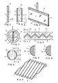
Figur 1 ein Element mit permeabler Wandung im Querschnitt, in Form einer Lamelle,Figur 2 das Element im Querschnitt in Form einer Platte oder eines Rohres,Figur 3 in schematischem Querschnitt ein Element, angeordnet in einem Gefäss, welches mit einem Raum umgeben ist,Figur 4 ein Ausführungsbeispiel des Elements in perspektivischer Darstellung, teilweise geschnitten,Figur 5 ein geformtes Element, eingebaut in einem Gefäss in Aufsicht, gemäss dem vertikalen Pfeil inFigur 3,Figur 6 einen Querschnitt durch die Struktur inFigur 5 gemäss der Linie A/A inFigur 5,- Figur 7 ein Element in Form einer gewellten Lamelle,
Figuren 8 und 9 einen Querschnitt durch einen ersten und durch einen zweiten Abschnitt eines Gefässes mit den Elementen,Figur 10 ein Element, geformt zu einem schraubenförmigen, statischen Mischer, eingebaut in einem Gefäss in schematischer, perspektivischer Darstellung,Figur 11 Elemente in Form eines Rohres, zusammengestellt zu einem statischen Mischer, in schematischer Darstellung,Figur 12 plattenförmige Elemente, zusammengebaut zu einem statischen Mischer in schematischer Darstellung,Figur 13 lamellenförmige, gewellte Elemente zusammengebaut zu einem statischen Mischer in schematischer Darstellung,Figur 14 einen statischen Mischer bildendes Element, eingebaut in einem Gefäss in der Sicht, gemäss Linie B/B inFigur 6.
- 1 shows an element with a permeable wall in cross section, in the form of a lamella,
- FIG. 2 shows the element in cross section in the form of a plate or a tube,
- FIG. 3 shows a schematic cross section of an element arranged in a vessel which is surrounded by a space,
- FIG. 4 shows an exemplary embodiment of the element in a perspective illustration, partially in section,
- 5 shows a shaped element, installed in a vessel under supervision, according to the vertical arrow in FIG. 3,
- FIG. 6 shows a cross section through the structure in FIG. 5 along the line A / A in FIG. 5,
- FIG. 7 shows an element in the form of a corrugated lamella,
- FIGS. 8 and 9 show a cross section through a first and through a second section of a vessel with the elements,
- FIG. 10 shows an element, shaped into a helical, static mixer, installed in a vessel in a schematic, perspective illustration,
- FIG. 11 elements in the form of a tube, put together to form a static mixer, in a schematic illustration,
- FIG. 12 plate-shaped elements, assembled to form a static mixer in a schematic representation,
- FIG. 13 lamellar, corrugated elements assembled into a static mixer in a schematic representation,
- FIG. 14 an element forming a static mixer, installed in a vessel in the view, according to line B / B in FIG. 6.
Das Element, wie es z.B. in Figur 1 oder 2 besonders klar dargestellt ist, weist eine permeable Wandung 1 auf. Diese Wandung stützt sich auf ein Stützgitter 19. Wie es in Figur 1 dargestellt ist, kann das Stützgitter 19 selber einen Innenraum 4 bilden, der von der Wandung 1 begrenzt ist. Die Figur 2 zeigt die weitere Möglichkeit, wo der Innenraum 4 des Elementes zwischen zwei Stützgitterstrukturen gebildet ist. Wie gezeigt, kann die tragende Struktur des Stützgitters aus Traggeflechten gebildet werden, die eine innere Durchlässigkeit aufweisen, und wenn sie an den Grenzflächen zu einem Fluidstrom mit Wandungen bedeckt sind, müssen die tragenden Strukturen mindestens dreimal grössere mittlere Durchlassöffnungen aufweisen, als es das Material der Wandung aufweist, um einen Fluss des Fluids durch den Innenraum 4 zu ermöglichen.The element as e.g. is shown particularly clearly in FIG. 1 or 2, has a
Im Falle der Figur 1 handelt es sich um ein Element, das in Form einer Lamelle gebaut ist. Im Falle der Figur 2 kann es sich um ein Element handeln, das in Form einer Platte oder auch in Form eines Rohres gebaut ist. Das Element ist so geformt, dass es alleine, wie es z.B. in Figur 5 bzw. 6 zu sehen ist, einen Turbulenzgenerator 8 bildet. Die in der Figur 5 bzw. in Figur 6 dargestellte Form des Elements ist eine einfach gewellte Platte, die unter Umständen die Funktion eines Turbulenzgenerators vertreten kann. Eine solche einzelne gewellte Lamelle oder auch gewellte Platte ist in perspektivischer Darstellung in Figur 7 zu sehen.In the case of Figure 1, it is an element that is built in the form of a lamella. In the case of Figure 2, it can be an element that is built in the form of a plate or in the form of a tube. The element is shaped such that it alone forms a
In anderen Fällen werden eine Anzahl von ähnlich geformten Elementen zu einem Modul zusammengestellt, so dass ein Turbulenzgenerator gestaltet ist, welcher einen statischen Mischer 8 bildet. Beispiele solcher zu statischen Mischern zusammengebauten, erfindungsgemässen Elemente sind in den Figuren 10, 11, 12 und 13 gezeigt. Dabei wird der statische Mischer 8, der in der Figur 10 dargestellt ist, ein erfindungsgemässes Element, welches zu einer Schraubenform geformt ist, in einem rohrartigen Gefäss 3 von einem Fluidstrom 2 umflossen. Der statische Mischer 8, gemäss Figur 11, wird von erfindungsgemässen Elementen in Form von Röhrchen zusammengebaut. Die Röhrchen in den einzelnen Lagen 16 des Mischers 8 kreuzen einander. Der statische Mischer gemäss Figur 12 weist plattenförmige Elemente auf, deren Wände mit turbulenzerzeugenden Flügeln 21 versehen sind, wobei die Richtung der Flügel abwechselnd an den einzelnen plattenartigen Elementen 18 einander kreuzt. Der Turbulenzgenerator 8, der in Figur 13 gezeigt ist, ist zusammengestellt aus lamellenförmigen Elementen 9, die gewellt sind.In other cases, a number of similarly shaped elements are put together to form a module, so that a turbulence generator is designed which forms a
Das Element mit der permeablen Wandung 1 ist in einem einen Fluidstrom, welcher mit Pfeilen 2 angedeutet ist, aufnehmenden Gefäss 3 angeordnet. Die Wandung 1 ist mindestens für eine Komponente des Fluids durchlässig und grenzt einen Innenraum 4 des Elements ab. Dieser ist an einen Raum 5 ausserhalb des Gefässes 3 durch die Gefässwand 10 angeschlossen. Dieses ist am besten anhand der Figur 3 gezeigt, wo der Innenraum 4 mittels Leitungen 11 durch die Gefässwand 10 mit dem ausserhalb des Gefässes 3 sich befindlichen Raum 5 verbunden ist. Genau so anschaulich ist dieses mittels Figur 6 gezeigt, die zusammen mit der Figur 5 ein in einem Rohrstück 10 eingebautes gewelltes Element zeigt, dessen Innenraum 4 durch die Wand 10 des rohrförmigen Gefässes 3 in einen Raum 5 ausserhalb des Gefässes 3 unmittelbar mündet.The element with the
Falls es sich um eine Anwendung des Elements als Filterelement handelt, so ist die Wandung nur für eine Komponente des Fluidstromes 2 in dem Gefäss 3 durchlässig, welche als Filtrat durch die Wandung 1 und durch den Innenraum 4 im Kreuzstrom in den Raum 5 ausserhalb des Gefässes 3 fliesst.If the element is used as a filter element, the wall is only permeable to a component of the
Falls das Element zum Eintragen eines anderen Fluids, z.B. eines Gases oder einer Nahrungslösung in den Fluidstrom 2 in dem Gefäss 3 angewendet werden soll, dann ist die Wandung 1 für ein solches Fluid durchlässig, welches dann aus dem Raum 5 ausserhalb des Gefässes 3 durch den Innenraum 4 und durch die Wandung 1 im Kreuzstrom fliesst, um zu dem Fluidstrom 2 in dem Gefäss 3 gemischt zu werden. Beschrieben anhand der Figur 3 käme das beizumischende Fluid aus dem Raum 5 durch die rohrförmigen Verbindungsteile 11 in den Innenraum 4 und fliesst im Kreuzstrom durch die Wandung 1 hinein in den Fluidstrom 2 in dem Gefäss 3, zu welchem es beigemischt wird.If the element for introducing another fluid, e.g. of a gas or a food solution to be used in the
Die Wandung 1 kann mindestens eine Materialschichtlage aufweisen, deren Permeabilität dermassen ist, beziehungsweise deren Poren so dimensioniert sind, dass die Wandung die Filtrationsfunktion des Elements in dem Mikro- bis Ultrafiltrations-Bereich ausüben kann. In einem solchen Falle könnte die erwähnte Materialschichtlage eine semipermeable Membran sein.The
Das Element kann, wie es in Figuren 5, 7, 13, 14 gezeigt ist, eine Form einer Platte oder einer Folie haben, die gewellt sind. Wenn möglich kann eine solche gewölbte Platte oder Folie selbst die Funktion eines Turbulenzgenerators in Form eines statischen Mischers vertreten, wie es in Figur 5 besonders deutlich gezeigt ist. In einem anderen Fall, der in Figur 13 schematisch gezeigt ist, an eine Anzahl solcher gewellten Elemente zu einem Turbulenzgenerator 8 in Form eines statischen Mischers zusammengebaut werden, auf die Weise, dass die Wellentäler der einzelnen, nebeneinander gestellten Elemente 9, 15 quer zueinander verlaufen.The element, as shown in Figures 5, 7, 13, 14, can have a shape of a plate or a film which is corrugated. If possible, such a curved plate or film itself can act as a turbulence generator in the form of a static mixer, as is particularly clearly shown in FIG. In another case, which is shown schematically in FIG. 13, a number of such corrugated elements are assembled to form a
Die Verbindung des Innenraumes 4 kann, wie es in Figur 6 gezeigt ist, direkt durch die Wand 10 des Gefässes in einen Raum 5 ausserhalb des Gefässes münden. Dies ist der Fall, der in Figur 5 und 6 dargestellt ist.The connection of the
Es ist auch möglich und in Figur 3 dargestellt, dass der Innenraum 4 mittels eines, die permeable Wandung 1 und die Gefässwand 10 durchsetzenden Leitungsstückes 11 an den Raum 5 ausserhalb des Gefässes 3 angeschlossen ist. In der Figur 3 ist ein solcher Raum 5 als ein Raum dargestellt, der durch eine Zylinderwand 22 begrenzt ist.It is also possible and shown in FIG. 3 that the
Eine andere vorstellbare Verbindung zwischen dem Innenraum 4 und dem Raum 5 ausserhalb des Gefässes ist in Figur 4 dargestellt, wo das Element in einem Rahmen 13 eingefasst ist, welcher den Innenraum ringsherum dicht umfasst und aus welchem ein Verbindungsrohrstück 14 zu einem Raum 5 führt.Another conceivable connection between the interior 4 and the
Wie es aus den Vorbildern der bisherigen statischen Mischer angeregt ist, kann durch das Element eine durch die Wandung 1 und durch den Innenraum 4, gegen diesen geschlossene Oeffnung, 20 in Figur 13, führen, so dass der Fluidstrom 2 in dem Gefäss 3 nicht nur entlang der Wandung 1 des Elements, sondern auch durch dieses fliessen kann, und so seine Richtung nicht nur entlang des Elements, sondern auch durch das Element ändern kann.As suggested by the models of the previous static mixers, an opening through the
Wie es in Figur 13 angedeutet ist, können diese durchsetzenden Oeffnungen 20 rohrförmig sein. Sie können auch andere Formen haben, z.B. schlitzförmig sein, wie es am Beispiel der Figur 11 gezeigt ist, wo die rohrförmigen Elemente mit Schlitzen 12 versehen sind.As indicated in FIG. 13, these penetrating
Die Materialschichtlage, die die Mikro- bis Ultrafiltration des Elementes ermöglichen soll, kann eine Schicht von Polysulfon sein, die auf ein aus mehreren Lagen zusammengesintertes Stützgitter 19 aufgetragen ist und hinein imprägniert ist.The layer of material layer which is to enable the micro- to ultrafiltration of the element can be a layer of polysulfone which is applied to a
Es wäre auch vorstellbar, das Element so zu gestalten, dass der Innenraum 4 nur von einer Seite mit der permeablen Wandung 1 versehen ist. Die andere Seite des Innenraums 4 kann mit einer undurchlässigen Wand begrenzt werden. Dies dürfte jedoch ein Ausnahmefall sein, normalerweise wird der Innenraum 4 von beiden Seiten mit einer permeablen Wandung 1 versehen sein.It would also be conceivable to design the element such that the
In den Figuren 8 und 9 ist anschaulich gemacht, dass die gewellten, lamellenförmigen Elemente nebeneinander parallel zueinander gestellt werden können, wobei in einem ersten Abschnitt die Lamellen in einer Lage liegen, die gegenüber der Lage der Lamellen in dem gleich nachfolgenden Abschnitt des Turbulenzgenerators um 90° im Raum versetzt sind.In FIGS. 8 and 9, it is made clear that the corrugated, lamellar elements can be placed next to one another parallel to one another, with the lamellae in a first section being in a position that is 90 relative to the position of the lamellae in the immediately following section of the turbulence generator ° are offset in space.
Diese Regel der Versetzung der Leitungswege ist bei allen den hier dargestellten Beispielen der Turbulenzgeneratoren in Figuren 11, 12 oder 13 auch gezeigt. Auch hier wird die Strömungsrichtung mehrmals hintereinander umgelenkt. Dadurch wird eben die vorher erwähnte Wirbelung erzielt, die immer neue Schichten in die Nähe der Wandung 1 bringt, so dass jedes Teilchen des Fluidstromes die Möglichkeit bekommt, über eine suffiziente Zeit mit der Wandung in Berührung zu kommen.This rule of displacement of the line paths is also shown in all the examples of the turbulence generators shown here in FIGS. 11, 12 or 13. Here, too, the direction of flow is redirected several times in succession. As a result, the aforementioned vortex is achieved, which always brings new layers into the vicinity of the
Ein interessantes Anwendungsgebiet bietet sich für die erfindungsgemässen, zu Turbulenzgeneratoren zusammengestellten Elemente in der Fliessbettreaktoren-Technik an. In diesen Reaktoren, besonders in den schwierigen technischen Gebieten, wie es z.B. die Techniken zu Kultivationen von lebenden Zellen darstellen, werden Turbulenzgeneratoren dazu eingesetzt, um das Kultivationsfliessbett in ständiger Durchmischung zu halten und zu verhindern, dass es zur unkontrollierbaren Wirbelung in dem Fliessbett kommt, oder dass es zur wiederholten Zusammenmischung von Elementen kommt, die vorher schon einmal voneinander getrennt worden sind. Auf die oben beschriebene Weise kann man nämlich durch die zu erfindungsgemässen Turbulenzgeneratoren 8 zusammengebauten Elemente ein Fluid aus dem Raum 5 ausserhalb des Reaktionsgefässes führen, um z.B. das Fluidbett auf diese Weise zu begasen. Durch geeignete Struktur der Wandung 1, d.h. durch ihre Beschickung mit einer geeigneten porösen Membran lässt sich in so einem Reaktor eine blasenfreie Begasung in situ erreichen.An interesting field of application is for the elements according to the invention, which are combined to form turbulence generators in fluid bed reactor technology. In these reactors, especially in the difficult technical fields, such as, for example, the techniques for cultivating living cells, turbulence generators are used to keep the cultivation fluid bed in constant mixing and to prevent uncontrollable swirling in the fluid bed or repeated mixing of elements that have previously been separated from one another. In the manner described above, a fluid can be guided from the
Anhand der Figur 14 soll eine mögliche Methode zur Fabrikation einer Vorrichtung erläutert werden, wo ein erfindungsgemässes Element mit der Wandung und dem Innenraum in einem rohrartigen Gefäss eingebaut ist. Es wird dann so verfahren, dass das lamellenförmige Element zuerst gewellt wird und dann in ein Rohr von einem grösseren Durchmesser als das fertige Gefäss dann haben soll eingesetzt wird. Das Element ist in diesem Rohr von einem Durchmesser D 3 in Figur 4 so eingesetzt, dass sein Innenraum im Querschnitt radial auswärts weist. Dieses Rohr, in dem das Element eingesetzt ist wird rotiert. Dabei wird in dieses Rohr ein hartbarer Harzstoff hineingegossen, der an der rotierenden Innenwand eine Schicht bildet, die die Ränder des eingesteckten Elements umfasst. Nach Aushärtung des eingegossenen Kunststoffes wird das damit hergestellte Rohr mit dem eingefassten Element aus der Büchse herausgenommen. Danach wird eine Aussenschicht der Wand des vorfabrizierten Rohres abgeschliffen oder abgedreht, so dass die Innenräume 4 von aussen zugänglich sind. Das Abschleifen bzw. Abdrehen der Oberfläche des Rohres geschieht bis zu dem in der Figur 14 angedeuteten Durchmesser D 2. Zu diesem Zustand bearbeitet, entsteht eine Einheit, bei der der Innenraum des Elements nach aussen in einen Raum ausserhalb des Raumes des Gefässes 3 geöffnet ist. Diese Einheit wird jetzt in ein zweites Rohr mit einem inneren Durchmesser, der so gross sein kann wie der in Figur 14 angegebene Durchmesser D 3 eingesteckt. Dadurch entsteht ein Gebilde, das dem in der Figur 3 dargestellten ähnlich ist. Wenn es sich um eine Anordnung des Elements handeln würde, das in Figur 3 dargestellt ist, wo sein Innenraum 4 mit dem Raum 5 durch Röhrchen 11 verbunden ist, könnte eine solche Einheit genau auf die gleiche Weise fabriziert werden, wie sie vorher mit Bezug auf die Figur 14 beschrieben wurde. Es müsste jedoch der Innenraum 4 an der Wand 10 an einer Stelle 17 gegen den Fluidstrom 2 abgedichtet sein. Es ist gezeigt, dass das Gefäss 3 mit seiner Gefässwand 10 in einem grösseren Rohr 22 eingesteckt ist, zwischen dem und der Wand 10 ein Raum 5, der ausserhalb des Raumes des Gefässes 3 liegt, zu sehen ist. Der Innenraum 4 ist in diesem Fall mittels der Leitungsstücke 11, die die Wandung 1 und die Gefässwand 10 durchsetzen, verbunden.A possible method for manufacturing a device is to be explained on the basis of FIG. 14, where an element according to the invention is installed with the wall and the interior in a tubular vessel. The procedure is then that the lamellar element is first corrugated and then inserted into a tube of a larger diameter than the finished vessel should have. The element is inserted in this tube with a
Claims (17)
dadurch gekennzeichnet, dass das Element in Form einer Platte, Lamelle oder eines Rohres gebaut ist, und dass seine permeable Wandung (1) gegenüber dem umfliessenden Fluidstrom (2) alleine, oder mit weiteren ähnlich geformten Elementen zu einem Modul zusammengestellt, einen Turbulenzgenerator (8) in Gestalt eines statischen Mischers bildet.1. element with permeable wall (1), which is arranged in a vessel (3) receiving a fluid stream (2), the wall (1) being permeable to at least part of the fluid and delimiting an interior (4) of the element, which is connected to a room (5) outside the vessel (3) through the vessel wall (10),
characterized in that the element is constructed in the form of a plate, lamella or a tube, and that its permeable wall (1) with respect to the flowing fluid stream (2) alone or combined with other similarly shaped elements to form a module, a turbulence generator (8 ) in the form of a static mixer.
Priority Applications (1)
| Application Number | Priority Date | Filing Date | Title |
|---|---|---|---|
| AT86115521T ATE60523T1 (en) | 1985-11-22 | 1986-11-08 | ELEMENT WITH PERMEABLE WALL. |
Applications Claiming Priority (2)
| Application Number | Priority Date | Filing Date | Title |
|---|---|---|---|
| CH4993/85 | 1985-11-22 | ||
| CH4993/85A CH670573A5 (en) | 1985-11-22 | 1985-11-22 |
Publications (2)
| Publication Number | Publication Date |
|---|---|
| EP0226788A1 true EP0226788A1 (en) | 1987-07-01 |
| EP0226788B1 EP0226788B1 (en) | 1991-01-30 |
Family
ID=4286086
Family Applications (1)
| Application Number | Title | Priority Date | Filing Date |
|---|---|---|---|
| EP86115521A Expired - Lifetime EP0226788B1 (en) | 1985-11-22 | 1986-11-08 | Element with a permeable side |
Country Status (7)
| Country | Link |
|---|---|
| US (1) | US4902418A (en) |
| EP (1) | EP0226788B1 (en) |
| JP (1) | JPS62125807A (en) |
| AT (1) | ATE60523T1 (en) |
| CA (1) | CA1292170C (en) |
| CH (1) | CH670573A5 (en) |
| DE (1) | DE3677352D1 (en) |
Cited By (3)
| Publication number | Priority date | Publication date | Assignee | Title |
|---|---|---|---|---|
| EP0947239A2 (en) * | 1998-03-27 | 1999-10-06 | Bayer Ag | Static mixer |
| WO2008116872A1 (en) * | 2007-03-27 | 2008-10-02 | Rwth Aachen | Membrane device and method for the production of a membrane device |
| DE102020102420A1 (en) | 2020-01-31 | 2021-08-05 | Rwth Aachen | Gas-liquid reactor for bubble-free gassing of a process liquid |
Families Citing this family (31)
| Publication number | Priority date | Publication date | Assignee | Title |
|---|---|---|---|---|
| JP2686078B2 (en) * | 1987-07-16 | 1997-12-08 | 久夫 小嶋 | Mixing element |
| FI82670C (en) * | 1989-01-27 | 1991-04-10 | Kemira Oy | Process for producing hydrogen peroxide |
| CH678154A5 (en) * | 1989-04-26 | 1991-08-15 | Robert Andreae | |
| US5312185A (en) * | 1989-12-28 | 1994-05-17 | Hisao Kojima | Motionless mixer and method for manufacturing the same |
| US5476783A (en) * | 1992-03-23 | 1995-12-19 | Koch Engineering Company, Inc. | Bioreactor method of culturing and propagating cells with a woven motionless mixing element |
| US5407274A (en) * | 1992-11-27 | 1995-04-18 | Texaco Inc. | Device to equalize steam quality in pipe networks |
| US5709468A (en) * | 1992-11-27 | 1998-01-20 | Texaco Group, Inc. | Method for equalizing steam quality in pipe networks |
| AU703488B2 (en) | 1995-06-30 | 1999-03-25 | Pall Corporation | Separation systems and methods |
| AU761781B2 (en) * | 1998-05-23 | 2003-06-12 | Enersyst Development Center, L.L.C. | High heat transfer rate convection oven with grease management and smoke reduction capabilities |
| JP2002516745A (en) * | 1998-05-29 | 2002-06-11 | エービービー ラーマス グローバル インコーポレイテッド | Structured packing and its components |
| US6273938B1 (en) * | 1999-08-13 | 2001-08-14 | 3M Innovative Properties Company | Channel flow filter |
| GB9923626D0 (en) * | 1999-10-07 | 1999-12-08 | Univ Newcastle | Novel porous element and use thereof |
| US6667017B2 (en) | 1999-10-15 | 2003-12-23 | Abb Lummus Global, Inc. | Process for removing environmentally harmful compounds |
| ES2278639T3 (en) * | 1999-10-15 | 2007-08-16 | Abb Lummus Global Inc. | CONVERSION OF NITROGEN OXIDES IN THE PRESENCE OF A CATALYST SUPPORTED BY A MESH TYPE STRUCTURE. |
| DE10055785A1 (en) * | 2000-11-10 | 2002-06-06 | Gummi Jaeger Kg Gmbh & Cie | Aerator for feeding large and small diameter air bubbles into waste water has elastomeric sleeve with slits, through which air emerges, on support with rectangular cross-section, larger sides of rectangle being very much larger than shorter |
| GB0316864D0 (en) * | 2003-07-18 | 2003-08-20 | Linertech Ltd | Improvements in and relating to container liners |
| US7467523B2 (en) * | 2003-08-26 | 2008-12-23 | Aqwest, Llc | Autonomous water source |
| US7363769B2 (en) * | 2005-03-09 | 2008-04-29 | Kelix Heat Transfer Systems, Llc | Electromagnetic signal transmission/reception tower and accompanying base station employing system of coaxial-flow heat exchanging structures installed in well bores to thermally control the environment housing electronic equipment within the base station |
| US7472895B2 (en) * | 2005-04-25 | 2009-01-06 | Watt Ronald D | Wood air diffuser for use in saltwater aquarium foam fractionators |
| CA2584955C (en) * | 2006-05-15 | 2014-12-02 | Sulzer Chemtech Ag | A static mixer |
| US7905358B2 (en) * | 2006-07-07 | 2011-03-15 | Alliant Techsystems Inc. | Apparatus and methods for filtering granular solid material |
| GB0621388D0 (en) * | 2006-10-27 | 2006-12-06 | Rolls Royce Plc | A support matrix arrangement |
| US9885154B2 (en) | 2009-01-28 | 2018-02-06 | Donaldson Company, Inc. | Fibrous media |
| CH701558A2 (en) | 2009-07-31 | 2011-01-31 | Alex Knobel | Device and method for mixing and exchange of fluids. |
| JP5629556B2 (en) * | 2010-11-10 | 2014-11-19 | ダイムラー・アクチェンゲゼルシャフトDaimler AG | Filtration structure |
| WO2012103280A1 (en) | 2011-01-28 | 2012-08-02 | Donaldson Company, Inc. | Method and apparatus for forming a fibrous media |
| WO2012103547A1 (en) | 2011-01-28 | 2012-08-02 | Donaldson Company, Inc. | Method and apparatus for forming a fibrous media |
| KR101320467B1 (en) * | 2011-10-26 | 2013-10-22 | 주식회사 부강테크 | Filtering Apparatus having Fixed-Type Chaos-Flow Inducer |
| US9713893B2 (en) * | 2013-07-09 | 2017-07-25 | Wenger Manufacturing, Inc. | Method of preconditioning comestible materials using steam/water static mixer |
| JP2016014381A (en) * | 2014-07-03 | 2016-01-28 | ナブテスコ株式会社 | Vehicular air compression device |
| WO2018235210A1 (en) * | 2017-06-21 | 2018-12-27 | エム・テクニック株式会社 | Filtration membrane module and filtration method |
Citations (7)
| Publication number | Priority date | Publication date | Assignee | Title |
|---|---|---|---|---|
| FR1093157A (en) * | 1953-02-11 | 1955-05-02 | Lorraine Carbone | Apparatus for bringing gases or vapors into contact with liquids |
| GB1298072A (en) * | 1969-06-18 | 1972-11-29 | Apv Co Ltd | Improvements in or relating to the treatment of liquids |
| FR2134377A1 (en) * | 1971-04-29 | 1972-12-08 | Sulzer Ag | |
| FR2231408A1 (en) * | 1973-05-29 | 1974-12-27 | Bentley Lab | |
| FR2271857A1 (en) * | 1974-05-24 | 1975-12-19 | Johnson & Johnson | |
| US4207182A (en) * | 1975-11-14 | 1980-06-10 | Rhone-Poulenc Industries | Polymeric compositions for membranes |
| GB1592771A (en) * | 1977-09-15 | 1981-07-08 | Bellhouse F H | Apparatus for heat or mass transfer |
Family Cites Families (18)
| Publication number | Priority date | Publication date | Assignee | Title |
|---|---|---|---|---|
| US3051462A (en) * | 1959-03-12 | 1962-08-28 | Anthony A Fennell | Method and means for operating a soaking pit |
| US3190618A (en) * | 1963-04-30 | 1965-06-22 | Katzen Raphael | Fluid mixer |
| US3491021A (en) * | 1967-10-18 | 1970-01-20 | Morgan G Huntington | Method and apparatus for non-cyclic concentration of solution-suspension |
| US3620895A (en) * | 1969-01-03 | 1971-11-16 | Polaroid Corp | Corrugated micropermeable membrane |
| US3616928A (en) * | 1969-10-02 | 1971-11-02 | Du Pont | Permeation separation device for separating fluids |
| US3774771A (en) * | 1971-12-09 | 1973-11-27 | Interior | Reverse osmosis module |
| CH563802A5 (en) * | 1973-04-18 | 1975-07-15 | Sulzer Ag | |
| FR2231787B1 (en) * | 1973-06-01 | 1977-02-11 | Rhone Poulenc Ind | |
| US4043539A (en) * | 1975-03-28 | 1977-08-23 | Texaco Inc. | Method and apparatus for static type fluid mixing |
| DE2722025A1 (en) * | 1977-05-16 | 1978-11-30 | Hoechst Ag | MEMBRANE UNIT, DEVICE WITH MEMBRANE UNIT, AND METHOD OF BLOOD PURIFICATION |
| SE7812682L (en) * | 1978-01-05 | 1979-07-06 | Kuesters Eduard | FILTER DEVICE |
| US4261834A (en) * | 1978-05-18 | 1981-04-14 | Millipore Corporation | Device and process for removing pyrogens from aqueous solutions |
| ZA796243B (en) * | 1978-11-22 | 1980-11-26 | B Bellhouse | Transfer membrane apparatus |
| EP0048730A1 (en) * | 1980-03-24 | 1982-04-07 | Baxter Travenol Laboratories, Inc. | Tubular channel diffusion device having flow guides therein |
| FR2505204B1 (en) * | 1981-05-05 | 1985-09-27 | Alsthom Atlantique | DEVICE FOR MIXING FLUIDS IN CIRCULATION |
| JPS57209604A (en) * | 1981-06-19 | 1982-12-23 | Daicel Chem Ind Ltd | Separator element of membrane |
| JPS60500005A (en) * | 1982-12-07 | 1985-01-10 | ベルハウス ブリアン ジヨン | Transmission membrane device |
| JPS6140725A (en) * | 1984-07-31 | 1986-02-27 | 江口 節子 | Power source apparatus by air bubbles |
-
1985
- 1985-11-22 CH CH4993/85A patent/CH670573A5/de not_active IP Right Cessation
-
1986
- 1986-10-27 JP JP61255542A patent/JPS62125807A/en active Pending
- 1986-11-06 US US06/927,849 patent/US4902418A/en not_active Expired - Lifetime
- 1986-11-08 AT AT86115521T patent/ATE60523T1/en not_active IP Right Cessation
- 1986-11-08 EP EP86115521A patent/EP0226788B1/en not_active Expired - Lifetime
- 1986-11-08 DE DE8686115521T patent/DE3677352D1/en not_active Expired - Fee Related
- 1986-11-21 CA CA000523513A patent/CA1292170C/en not_active Expired - Fee Related
Patent Citations (7)
| Publication number | Priority date | Publication date | Assignee | Title |
|---|---|---|---|---|
| FR1093157A (en) * | 1953-02-11 | 1955-05-02 | Lorraine Carbone | Apparatus for bringing gases or vapors into contact with liquids |
| GB1298072A (en) * | 1969-06-18 | 1972-11-29 | Apv Co Ltd | Improvements in or relating to the treatment of liquids |
| FR2134377A1 (en) * | 1971-04-29 | 1972-12-08 | Sulzer Ag | |
| FR2231408A1 (en) * | 1973-05-29 | 1974-12-27 | Bentley Lab | |
| FR2271857A1 (en) * | 1974-05-24 | 1975-12-19 | Johnson & Johnson | |
| US4207182A (en) * | 1975-11-14 | 1980-06-10 | Rhone-Poulenc Industries | Polymeric compositions for membranes |
| GB1592771A (en) * | 1977-09-15 | 1981-07-08 | Bellhouse F H | Apparatus for heat or mass transfer |
Cited By (5)
| Publication number | Priority date | Publication date | Assignee | Title |
|---|---|---|---|---|
| EP0947239A2 (en) * | 1998-03-27 | 1999-10-06 | Bayer Ag | Static mixer |
| EP0947239A3 (en) * | 1998-03-27 | 2000-07-12 | Bayer Ag | Static mixer |
| US7390121B2 (en) | 1998-03-27 | 2008-06-24 | Bayer Aktiengesellschaft | Static mixer module |
| WO2008116872A1 (en) * | 2007-03-27 | 2008-10-02 | Rwth Aachen | Membrane device and method for the production of a membrane device |
| DE102020102420A1 (en) | 2020-01-31 | 2021-08-05 | Rwth Aachen | Gas-liquid reactor for bubble-free gassing of a process liquid |
Also Published As
| Publication number | Publication date |
|---|---|
| CA1292170C (en) | 1991-11-19 |
| CH670573A5 (en) | 1989-06-30 |
| EP0226788B1 (en) | 1991-01-30 |
| ATE60523T1 (en) | 1991-02-15 |
| US4902418A (en) | 1990-02-20 |
| DE3677352D1 (en) | 1991-03-07 |
| JPS62125807A (en) | 1987-06-08 |
Similar Documents
| Publication | Publication Date | Title |
|---|---|---|
| EP0226788B1 (en) | Element with a permeable side | |
| EP0819101B1 (en) | Plant and process for oxidizing an aqueous medium | |
| DE69510661T3 (en) | USE OF BIOFILM CARRIER FOR WATER AND WASTE WATER CLEANING | |
| EP0892670B1 (en) | Device for filtering and separating flowing fluids | |
| EP0002422B1 (en) | Filtration device | |
| DE3803886C2 (en) | ||
| DE2324000B2 (en) | Device for the biological purification of waste water | |
| DE60120898T2 (en) | Particle filter for diesel engines | |
| DE2231868B2 (en) | Reverse osmosis cell | |
| DE2753788A1 (en) | DEVICE FOR DUSTING AND DISPERSING FLUIDA | |
| EP1166861A1 (en) | Mixer for mixing at least two gas streams or other Newtonian liquids | |
| EP1592489A2 (en) | Filtering device, filtering means, and filtration method | |
| EP0521495A2 (en) | Process and apparatus for manufacturing hollow fibre modules | |
| DE19544960A1 (en) | Device for filtering and separating flow media | |
| DE3916744A1 (en) | TUBULAR FILTER ELEMENT | |
| DE2508867B2 (en) | Device for heat or material exchange, which consists of several exchange spaces formed by parallel plates | |
| DE69926256T2 (en) | MONOLITICAL, POROUS SUPPORT FOR FILTER ELEMENT AND FILTER ELEMENT | |
| DE2814326A1 (en) | POROESE SUPPORT FOR USE IN A DIVIDER WITH HOLLOW FIBER | |
| DE2529977B2 (en) | Device with membranes on tubular supports for treating fluids | |
| DE10010387A1 (en) | Composite membrane used for purifying hydrogen for fuel cells comprises a support layer made from a first material and a permeation layer made from a second material arranged on the support layer | |
| EP2470291B9 (en) | Three-dimensionally braided hollow fiber module for mass and energy transfer operations | |
| WO2002094724A1 (en) | Device for biological fluid treatment | |
| EP0120264A2 (en) | Cross flow module with fine canals | |
| DE2558986A1 (en) | PACKING AND SYSTEM FOR THE ORGANIC TREATMENT OF WASTE WATER | |
| DE2436965C2 (en) | Filters for filtering liquids |
Legal Events
| Date | Code | Title | Description |
|---|---|---|---|
| PUAI | Public reference made under article 153(3) epc to a published international application that has entered the european phase |
Free format text: ORIGINAL CODE: 0009012 |
|
| AK | Designated contracting states |
Kind code of ref document: A1 Designated state(s): AT BE DE FR GB IT LU NL SE |
|
| 17P | Request for examination filed |
Effective date: 19870825 |
|
| 17Q | First examination report despatched |
Effective date: 19881028 |
|
| GRAA | (expected) grant |
Free format text: ORIGINAL CODE: 0009210 |
|
| ITF | It: translation for a ep patent filed |
Owner name: ING. ZINI MARANESI & C. S.R.L. |
|
| AK | Designated contracting states |
Kind code of ref document: B1 Designated state(s): AT BE DE FR GB IT LU NL SE |
|
| REF | Corresponds to: |
Ref document number: 60523 Country of ref document: AT Date of ref document: 19910215 Kind code of ref document: T |
|
| REF | Corresponds to: |
Ref document number: 3677352 Country of ref document: DE Date of ref document: 19910307 |
|
| ET | Fr: translation filed | ||
| GBT | Gb: translation of ep patent filed (gb section 77(6)(a)/1977) | ||
| PLBE | No opposition filed within time limit |
Free format text: ORIGINAL CODE: 0009261 |
|
| STAA | Information on the status of an ep patent application or granted ep patent |
Free format text: STATUS: NO OPPOSITION FILED WITHIN TIME LIMIT |
|
| 26N | No opposition filed | ||
| REG | Reference to a national code |
Ref country code: GB Ref legal event code: 732E |
|
| REG | Reference to a national code |
Ref country code: FR Ref legal event code: TP |
|
| PGFP | Annual fee paid to national office [announced via postgrant information from national office to epo] |
Ref country code: LU Payment date: 19930917 Year of fee payment: 8 |
|
| PGFP | Annual fee paid to national office [announced via postgrant information from national office to epo] |
Ref country code: FR Payment date: 19930928 Year of fee payment: 8 |
|
| PGFP | Annual fee paid to national office [announced via postgrant information from national office to epo] |
Ref country code: GB Payment date: 19931101 Year of fee payment: 8 |
|
| PGFP | Annual fee paid to national office [announced via postgrant information from national office to epo] |
Ref country code: BE Payment date: 19931112 Year of fee payment: 8 |
|
| PGFP | Annual fee paid to national office [announced via postgrant information from national office to epo] |
Ref country code: SE Payment date: 19931126 Year of fee payment: 8 |
|
| PGFP | Annual fee paid to national office [announced via postgrant information from national office to epo] |
Ref country code: NL Payment date: 19931130 Year of fee payment: 8 Ref country code: AT Payment date: 19931130 Year of fee payment: 8 |
|
| NLS | Nl: assignments of ep-patents |
Owner name: CHEMAP AG TE VOLKETSWIL, ZWITSERLAND. |
|
| EPTA | Lu: last paid annual fee | ||
| PGFP | Annual fee paid to national office [announced via postgrant information from national office to epo] |
Ref country code: DE Payment date: 19931216 Year of fee payment: 8 |
|
| PG25 | Lapsed in a contracting state [announced via postgrant information from national office to epo] |
Ref country code: LU Free format text: LAPSE BECAUSE OF NON-PAYMENT OF DUE FEES Effective date: 19941108 Ref country code: GB Effective date: 19941108 Ref country code: AT Effective date: 19941108 |
|
| PG25 | Lapsed in a contracting state [announced via postgrant information from national office to epo] |
Ref country code: SE Effective date: 19941109 |
|
| PG25 | Lapsed in a contracting state [announced via postgrant information from national office to epo] |
Ref country code: BE Effective date: 19941130 |
|
| EAL | Se: european patent in force in sweden |
Ref document number: 86115521.6 |
|
| BERE | Be: lapsed |
Owner name: GEBRUDER SULZER A.G. Effective date: 19941130 |
|
| PG25 | Lapsed in a contracting state [announced via postgrant information from national office to epo] |
Ref country code: NL Effective date: 19950601 |
|
| GBPC | Gb: european patent ceased through non-payment of renewal fee |
Effective date: 19941108 |
|
| NLV4 | Nl: lapsed or anulled due to non-payment of the annual fee | ||
| PG25 | Lapsed in a contracting state [announced via postgrant information from national office to epo] |
Ref country code: FR Effective date: 19950731 |
|
| PG25 | Lapsed in a contracting state [announced via postgrant information from national office to epo] |
Ref country code: DE Effective date: 19950801 |
|
| EUG | Se: european patent has lapsed |
Ref document number: 86115521.6 |
|
| REG | Reference to a national code |
Ref country code: FR Ref legal event code: ST |
|
| PG25 | Lapsed in a contracting state [announced via postgrant information from national office to epo] |
Ref country code: IT Free format text: LAPSE BECAUSE OF NON-PAYMENT OF DUE FEES;WARNING: LAPSES OF ITALIAN PATENTS WITH EFFECTIVE DATE BEFORE 2007 MAY HAVE OCCURRED AT ANY TIME BEFORE 2007. THE CORRECT EFFECTIVE DATE MAY BE DIFFERENT FROM THE ONE RECORDED. Effective date: 20051108 |