EP0226529B1 - Elektrische Türverriegelungsvorrichtung - Google Patents
Elektrische Türverriegelungsvorrichtung Download PDFInfo
- Publication number
- EP0226529B1 EP0226529B1 EP19860630189 EP86630189A EP0226529B1 EP 0226529 B1 EP0226529 B1 EP 0226529B1 EP 19860630189 EP19860630189 EP 19860630189 EP 86630189 A EP86630189 A EP 86630189A EP 0226529 B1 EP0226529 B1 EP 0226529B1
- Authority
- EP
- European Patent Office
- Prior art keywords
- rack
- spring
- rack means
- door
- travel path
- Prior art date
- Legal status (The legal status is an assumption and is not a legal conclusion. Google has not performed a legal analysis and makes no representation as to the accuracy of the status listed.)
- Expired - Lifetime
Links
Images

Classifications
-
- E—FIXED CONSTRUCTIONS
- E05—LOCKS; KEYS; WINDOW OR DOOR FITTINGS; SAFES
- E05B—LOCKS; ACCESSORIES THEREFOR; HANDCUFFS
- E05B81/00—Power-actuated vehicle locks
- E05B81/24—Power-actuated vehicle locks characterised by constructional features of the actuator or the power transmission
- E05B81/25—Actuators mounted separately from the lock and controlling the lock functions through mechanical connections
-
- Y—GENERAL TAGGING OF NEW TECHNOLOGICAL DEVELOPMENTS; GENERAL TAGGING OF CROSS-SECTIONAL TECHNOLOGIES SPANNING OVER SEVERAL SECTIONS OF THE IPC; TECHNICAL SUBJECTS COVERED BY FORMER USPC CROSS-REFERENCE ART COLLECTIONS [XRACs] AND DIGESTS
- Y10—TECHNICAL SUBJECTS COVERED BY FORMER USPC
- Y10S—TECHNICAL SUBJECTS COVERED BY FORMER USPC CROSS-REFERENCE ART COLLECTIONS [XRACs] AND DIGESTS
- Y10S292/00—Closure fasteners
- Y10S292/62—Lost motion connections
-
- Y—GENERAL TAGGING OF NEW TECHNOLOGICAL DEVELOPMENTS; GENERAL TAGGING OF CROSS-SECTIONAL TECHNOLOGIES SPANNING OVER SEVERAL SECTIONS OF THE IPC; TECHNICAL SUBJECTS COVERED BY FORMER USPC CROSS-REFERENCE ART COLLECTIONS [XRACs] AND DIGESTS
- Y10—TECHNICAL SUBJECTS COVERED BY FORMER USPC
- Y10T—TECHNICAL SUBJECTS COVERED BY FORMER US CLASSIFICATION
- Y10T292/00—Closure fasteners
- Y10T292/08—Bolts
- Y10T292/1043—Swinging
- Y10T292/1075—Operating means
- Y10T292/1082—Motor
-
- Y—GENERAL TAGGING OF NEW TECHNOLOGICAL DEVELOPMENTS; GENERAL TAGGING OF CROSS-SECTIONAL TECHNOLOGIES SPANNING OVER SEVERAL SECTIONS OF THE IPC; TECHNICAL SUBJECTS COVERED BY FORMER USPC CROSS-REFERENCE ART COLLECTIONS [XRACs] AND DIGESTS
- Y10—TECHNICAL SUBJECTS COVERED BY FORMER USPC
- Y10T—TECHNICAL SUBJECTS COVERED BY FORMER US CLASSIFICATION
- Y10T292/00—Closure fasteners
- Y10T292/57—Operators with knobs or handles
Definitions
- the present invention is directed to an improvement in the design of an electric door lock actuator, particularly of the type used in an automobile to lock and unlock the latching bolts in the automobile door. More particularly, the present invention is directed to a combination lost motion and spring displacement device for disconnecting the electric door lock actuator from the locking mechanism of the door once the mechanism has moved to a position to secure the latch in the locked or unlocked position.
- the typical system includes a latching bolt to secure the door to the frame of the automobile, an electric switch located on the inside of the door for locking or unlocking the bolt, a manually-displaceable handle inside of the door for unlatching the door, a manually-moveable button, slide or similar device for locking and unlocking a latching bolt in the door, and on the exterior of the door, a handle for latching and unlatching the door and a key opening for receipt of a key for unlocking or locking the latching bolts.
- the key-receiving mechanism may be designed to either manually unlock the latching bolts or to energize a motor to unlock the latching bolts. At this point in time, most key entry locks utilize the motion imparted by turning the key to unlock the latching bolts.
- the manual effort required to turn the key to unlock the latching bolt may be significant. If the ambient temperature is low, or there is insufficient lubrication, or a key is particularly weak, in any of the above events, the force required to manually unlock the latching bolt may be such that the key is either twisted or broken in the process and entry to the car is denied.
- back-driven is a term used to define the physical movement including rotation of the armature of the actuator motor, and the intermediate gearing between the armature and the door locking mechanism upon manual displacement by turning a key to gain entry to an area.
- U.S. Patent 4,290,634 discloses a series of devices for connecting the manual locking and unlocking button in a car to the motive means.
- a lost motion relationship is disclosed between items 63 and 62.
- Spring 64 is utilized to absorb excess energy from a flywheel.
- Figures 3 and 4 there is disclosed a mechanism for connecting an electric motor to the gear train which is connected to the manual locking button where the gear train is engaged upon sufficient centrifugal force being applied by the motor being operated.
- Figures 5-8 is a separate type of lost motion device utilized without springs as is the device in Figures 9-12.
- a still further type of device is shown in Figures 13-15.
- At least one car manufacturer utilizes an electric door lock actuator which includes an electric motor which drives a rotating mechanism using a spring for latching and unlatching a door.
- This spring which is a direct part of the drive system is wound when the motor is energized such that when the motor is de-energized, the spring unwinds causing the motor to be rotated backwards thereby allowing for manual operation of the locking mechanism without being required to back-drive the motor.
- US-A-4 290 634 discloses an electric door lock actuator according to the preamble of claim 1.
- Another object of the invention is to provide a safe, economical, reliable, easy to manufacture and utilize electric door lock actuator.
- an electric door lock actuator for driving a door latch locking means which includes a housing, a reciprocally-driven rack means mounted therein and having a defined travel path, motive means for driving the rack means, spring means positioned in said housing to be biased by the rack means when moving along the rack means travel path toward an end thereof, said spring means acting to displace the rack means from an end of the travel path when the motive means is not energized to a neutral position, a connecting member extending between the rack means and the door latch locking means, a lost motion coupling means collectively formed by said connecting member and rack means, said coupling allowing the rack means to displace the connecting means to drive the door latch locking means and allowing the spring means to displace the rack means without displacing the connecting member or latch locking mechanism, said rack means including a shouldered section moving with said rack means along said defined travel path; said spring means being mounted within said housing such that said spring means is biased by the linear motion of said shouldered section toward the end of said travel path of the rack
- the invention disclosed is a door lock and latch mechanism including manual means to lock and unlock said mechanism and electric means to lock and unlock said mechanism.
- the door lock and latch mechanism includes a means for connecting the electric means to the remainder of said mechanism in such a manner that the manual means for operating said mechanism may be utilized without the necessity of driving the electric means, said means for connecting including a lost motion coupling connecting the electric means and the remainder of the mechanism and a spring means positioned to cause relative motion in the lost motion coupling between the electric means an d the mechanism whereby the manual means to lock and unlock the mechanism may be utilized to effect movement of the mechanism without causing the electric means to be displaced.
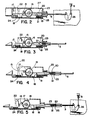
- Fig. 1 is a perspective view of an automobile door showing the typical location of the door latch and lock mechanism, the electric door lock actuator and control switch, and circuit therefor.
- Fig. 2 is a sectional view of the electric door lock actuator in accordance with the present invention showing the position of the components of the actuator at the extreme left range of travel.
- Fig. 3 is a sectional view of the electrical door lock actuator in accordance with the present invention showing the position of the components as the actuator is returned to a neutral position.
- Fig. 4 is a sectional view of the electrical door lock actuator in accordance with the present invention showing the position of the components as the actuator is travelling to the right.
- Fig. 5 is a sectional view of the electrical door lock actuator in accordance with the present invention showing the position of the components of the actuator at the extreme right range of travel.
- an electrically powered door lock actuator 1 is shown mounted between the inner and outer panels of an automobile door 2.
- a connecting link 3 extends from the actuator to a door latching and locking mechanism 4. The connecting link is driven back and forth by the actuator to engage and disengage the lock.
- a connecting rod 5 extends from the latch and lock mechanism to manual control button 6 located near the bottom edge of the window. This button is used to manually lock and unlock the door latching mechanism.
- a connecting rod 7 extends from the latch and lock mechanism to the key operated actuator 8 that is accessible from outside the door.
- a connecting rod 9 extends from the latch and lock mechanism to the door handle 10 that is used to unlatch the door.
- Conductors 11 and 12 supply current to the actuator from a battery 13 through a double pole, double throw control switch 14 located on the inner panel of the door.
- the arrangement of the various elements just described can be considered typical for an automobile door although slight variations in location of the components may vary from one type automobile to another. Almost without exception, however, there will be a means to manually latch a door from inside and outside the door, and a manual means to lock and unlock the latching means that will be located inside the door and outside the door.
- the electric actuator is mounted within the door and is connected by linkage to the manually actuated locking mechanism.
- the control switch for the electric actuator is mounted inside the automobile and is usually located on the inside panel of the door.
- an electrical switch is also incorporated in the key actuator so that when a key is inserted in the slot, a switch is closed which causes the electric actuator to unlock the latch.
- Figs. 2-5 show a detailed view of the electric door lock actuator in accordance with the present invention.
- the objective of the invention is to overcome a problem common on heretofore known systems. The problem centers around the fact that, because the electric actuator and the manual control for the lock are both connected to the same mechanism, inc reased physical force is required to unlock the latch simply because the electric actuator has to be "back-driven".
- pinion 15 is driven by a reversible motor 22.
- the pinion meshes with gear 16 that, in turn, meshes with rack gear 17 so that, as the motor driven pinion rotates in the clockwise direction, the rack will move to the right as viewed and to the left when the pinion rotates in a counterclockwise direction.
- rack gear moves to the right, a shouldered section 18 of the rack gear engages spring 19 and compresses the spring against housing 27 as the rack travels toward the right.
- a connecting link 3 Attached to the right end of the rack is a connecting link 3 that is secured within a cavity defined by the rack but that is free to move laterally with respect to the rack within predetermined limits.
- the freedom for the limited lateral movement is accomplished by means of a headed over section 23 of the connecting link that is free to move within cavity 20 provided in the rack that serves to contain, guide and limit the freedom of lateral movement of the link with respect to the rack. It is anticipated that this freedom of movement could be provided at some other location. For example, there could be an elongated slot provided on the member of the lock mechanism into which the connecting link attaches that would provide limited movement of the locking mechanism with respect to the connecting link, and this would effectively accomplish the same objective.
- FIG. 2-5 A complete operating cycle of the actuator can be followed by viewing Figs. 2-5 wherein like components in each figure are identified by the same number.
- the actuator is fully extended to the left as viewed, and motor 22 is energized.
- this position will be assumed to place the door lock in an unlocked position.
- motor 22 has already driven the rack gear 17 to the position and spring 24 is fully compressed.
- the head over portion of connecting link 3 is positioned against the right wall 25 of cavity 20.
- the rack gear moving to the left causing the headed over portion of the connecting link to contact wall 25 of cavity 20 at which time the connecting link then moved to the left with the rack thereby moving lock actuator arm 26 to the unlocked position as shown.
- Fig. 3 shows the position of the components after the control switch 14 is released, and motor 22 is no longer energized.
- spring 24 has forced the rack gear 17 to move to the right as compared to the position in Fig. 2. This has caused the right wall 25 of cavity 20 to move away from headed over section 23.
- the manual control lock button 6 can be moved to the locked or unlocked position without moving rack gear 17 because the headed over section 23 of connecting link 3 is free to move within cavity 20. In the position as shown, the manual mechanism is effectively disconnected from the electrical actuator.
Landscapes
- Lock And Its Accessories (AREA)
Claims (2)
- Elektrischer Türschloßstellantrieb zum Antreiben einer Türfallenverriegelungseinrichtung, mit:
einem Gehäuse (27);
einer hin und her angetriebenen Zahnstangeneinrichtung (17), die darin befestigt ist und eine festgelegte Bewegungsbahn hat;
einer Antriebseinrichtung (22) zum Antreiben der Zahnstangeneinrichtung (17);
einer Federeinrichtung (19, 24), die in dem Gehäuse (27) so angeordnet ist, daß sie durch die Zahnstangeneinrichtung gespannt wird, wenn diese sich längs der Zahnstangeneinrichtungsbewegungsbahn zu einem Ende derselben hin bewegt, wobei die Federeinrichtung bewirkt, daß die Zahnstangeneinrichtung (17) von einem Ende der Bewegungsbahn aus in eine neutrale Position bewegt wird, wenn die Antriebseinrichtung (22) nicht an Spannung liegt;
einem Verbindungsteil (3), das sich zwischen der Zahnstangeneinrichtung (17) und der Türfallenverriegelungseinrichtung (4) erstreckt; und
einer Totgangkupplung (20, 21, 23, 25), die durch das Verbindungsteil (3) und die Zahnstangeneinrichtung (17) gemeinsam gebildet ist, wobei die Kupplung der Zahnstangeneinrichtung (17) gestattet, das Verbindungsglied (3) zu bewegen, um die Türfallenverriegelungseinrichtung (4) anzutreiben, und der Federeinrichtung (19, 24) gestattet, die Zahnstangeneinrichtung (17) zu bewegen, ohne das Verbindungsteil (3) oder die Fallenverriegelungseinrichtung (4) zu bewegen,
dadurch gekennzeichnet,
daß die Zahnstangeneinrichtung einen Schulterabschnitt (18) aufweist, der sich mit der Zahnstangeneinrichtung längs der festgelegten Bewegungsbahn bewegt,
daß die Federeinrichtung (19, 24) so in dem Gehäuse befestigt ist, daß die Federeinrichtung (19, 24) durch die Linearbewegung des Schulterabschnitts (18) gespannt wird, wenn sich die Zahnstangeneinrichtung (17) dem Ende ihrer Bewegungsbahn nähert, und eine erste Feder (19) und eine zweite Feder (24) umfaßt, von denen eine Feder an jedem Ende der Zahnstangeneinrichtungsbewegungsbahn und in dem Gehäuse (27) angeordnet ist, wobei der Schulterabschnitt (18) der Zahnstangeneinrichtung (17) die passende Feder (19 oder 24) erfaßt und zusammendrückt, wenn sich die Zahnstangeneinrichtung (17) zu dem einen oder anderen Ende ihrer Bewegungsbahn bewegt. - Vorrichtung nach Anspruch 1, wobei die Totgangkupplung (20, 21, 23, 25) einen Totganghohlraum (20) aufweist, der in der Zahnstangeneinrichtung (17) gebildet ist, und einen Teil (23) größeren Durchmessers, der an dem Verbindungsteil (3) gebildet und innerhalb des Totganghohlraums (20) verschiebbar ist, wodurch die Zahnstangeneinrichtung (17) und das Verbindungsteil (3) relativ zueinander bewegt werden können, indem eine Verschiebebewegung zwischen der Zahnstangeneinrichtung (17) und dem Verbindungsteil (3) gestattet wird.
Applications Claiming Priority (2)
| Application Number | Priority Date | Filing Date | Title |
|---|---|---|---|
| US06/809,377 US4674781A (en) | 1985-12-16 | 1985-12-16 | Electric door lock actuator |
| US809377 | 2001-03-15 |
Publications (3)
| Publication Number | Publication Date |
|---|---|
| EP0226529A2 EP0226529A2 (de) | 1987-06-24 |
| EP0226529A3 EP0226529A3 (en) | 1988-05-11 |
| EP0226529B1 true EP0226529B1 (de) | 1992-03-11 |
Family
ID=25201201
Family Applications (1)
| Application Number | Title | Priority Date | Filing Date |
|---|---|---|---|
| EP19860630189 Expired - Lifetime EP0226529B1 (de) | 1985-12-16 | 1986-12-11 | Elektrische Türverriegelungsvorrichtung |
Country Status (5)
| Country | Link |
|---|---|
| US (1) | US4674781A (de) |
| EP (1) | EP0226529B1 (de) |
| CA (1) | CA1273215C (de) |
| DE (1) | DE3684260D1 (de) |
| MX (1) | MX161322A (de) |
Families Citing this family (84)
| Publication number | Priority date | Publication date | Assignee | Title |
|---|---|---|---|---|
| DE3627893A1 (de) * | 1986-08-16 | 1988-02-18 | Swf Auto Electric Gmbh | Stelleinrichtung, insbesondere zur tuerverriegelung bei kraftfahrzeugen |
| DE3703392A1 (de) * | 1987-02-05 | 1988-08-18 | Fichtel & Sachs Ag | Elektrische zentral-verriegelungs-einrichtung fuer tueren, hauben und/oder deckel insbesondere an kraftfahrzeugen |
| JPH0735708B2 (ja) * | 1987-11-30 | 1995-04-19 | 株式会社大井製作所 | 自動車用ドアロック装置 |
| US4850466A (en) * | 1988-05-19 | 1989-07-25 | General Motors Corporation | Clutch for power door lock actuator |
| US4893704A (en) * | 1989-03-27 | 1990-01-16 | General Motors Corporation | Power door lock actuator |
| US4946211A (en) * | 1989-04-24 | 1990-08-07 | General Motors Corporation | Latch control arrangement |
| US4969672A (en) * | 1989-05-15 | 1990-11-13 | General Motors Corporation | Deck lid release actuator |
| US5214332A (en) * | 1989-06-20 | 1993-05-25 | Alpha Corporation | Electric motor |
| AT398454B (de) * | 1992-04-01 | 1994-12-27 | Roto Frank Eisenwaren | Schloss, insbesondere mehrriegelschloss |
| US5653144A (en) * | 1993-02-09 | 1997-08-05 | Fenelon; Paul J. | Stress dissipation apparatus |
| ATE156886T1 (de) * | 1993-02-10 | 1997-08-15 | Atoma Int Inc | Lineaire antriebsbewegung |
| US5503441A (en) * | 1993-09-30 | 1996-04-02 | Stoneridge, Inc. | Double locking lock actuator |
| JP3023278B2 (ja) * | 1994-05-24 | 2000-03-21 | 三井金属鉱業株式会社 | 自動閉扉機構付車両ドアロック装置 |
| US5916327A (en) * | 1995-04-28 | 1999-06-29 | Ut Automotive Dearborn, Inc. | Multi-functional apparatus employing an electromagnetic device |
| US5694812A (en) * | 1995-04-28 | 1997-12-09 | United Technologies Automotive, Inc. | Multi-functional apparatus employing an electromagnetic device and an intermittent motion mechanism |
| US5949206A (en) * | 1995-04-28 | 1999-09-07 | Ut Automotive Dearborn, Inc. | Multi-functional apparatus employing an intermittent motion mechanism |
| US5903114A (en) * | 1995-04-28 | 1999-05-11 | Ut Automotive Dearborn, Inc. | Multi-functional apparatus employing an intermittent motion mechanism |
| US5920158A (en) * | 1995-04-28 | 1999-07-06 | Miller; Robin Mihekun | Multi-functional vehicle apparatus |
| US5983739A (en) * | 1995-09-01 | 1999-11-16 | Feder; David A. | Door lock actuator |
| US5634676A (en) * | 1995-09-01 | 1997-06-03 | Feder; David A. | Power door lock actuator |
| US5852943A (en) * | 1996-05-06 | 1998-12-29 | Ut Automotive Dearborn, Inc. | Door lock mechanism for an automotive vehicle |
| US5844382A (en) * | 1997-04-09 | 1998-12-01 | Ut Automotive Dearborn, Inc | Motion transmitting apparatus for use with an automotive vehicle multi-functional apparatus |
| US5969431A (en) * | 1997-10-08 | 1999-10-19 | Lear Automotive Dearborn, Inc. | Linearly actuating multi-functional apparatus for use in an automotive vehicle |
| US6075298A (en) * | 1997-10-09 | 2000-06-13 | Lear Automotive Dearborn, Inc | Rotary and linear translation actuator performing multi-functions in an automobile |
| US6003193A (en) * | 1997-10-09 | 1999-12-21 | Lear Automotive Dearborn, Inc. | Multi-functional apparatus having flexible clutch |
| US5889341A (en) * | 1997-10-09 | 1999-03-30 | Ut Automotive Dearborn, Inc. | Multi-functional apparatus employing a linear wiper |
| US5847519A (en) * | 1997-10-09 | 1998-12-08 | Ut Automotive Dearborn, Inc. | Multi-functional apparatus for a wiper and cable drive |
| US5953786A (en) * | 1997-10-09 | 1999-09-21 | Ut Automotive Dearborn, Inc. | Bypass loop wiper/washer system |
| US6020576A (en) * | 1997-10-09 | 2000-02-01 | Lear Automotive Dear Born, Inc. | Temperature and windshield crack detector |
| US6026536A (en) * | 1997-10-09 | 2000-02-22 | Lear Automotive Dearborn, Inc | Range limiting dual direction slip clutch |
| US5979256A (en) * | 1997-10-09 | 1999-11-09 | Ut Automotive Dearborn, Inc. | Gear drive window wiper and multi-function electric motor |
| US5986351A (en) * | 1997-10-09 | 1999-11-16 | Lear Automotive Dearborn, Inc. | Bi-directional lever for activating automotive liftgate lock mechanism |
| US5907199A (en) * | 1997-10-09 | 1999-05-25 | Ut Automotive Dearborn, Inc. | Electric motor providing multi-directional output |
| US5924324A (en) * | 1997-10-09 | 1999-07-20 | Ut Automotive Dearborn, Inc. | Movable gear drive windshield wiper |
| US5917298A (en) * | 1997-10-09 | 1999-06-29 | Ut Automotive Dearborn, Inc. | Electric motor control system with resistor network for automobile wiper assembly |
| US5907885A (en) * | 1997-10-09 | 1999-06-01 | Ut Automotive Dearborn, Inc. | Multi-functional apparatus for use in an automotive vehicle employing multiple tracks |
| US5920949A (en) * | 1997-10-09 | 1999-07-13 | Ut Automotive Dearborn, Inc. | Rocking wiper mechanism |
| US5977678A (en) * | 1997-10-09 | 1999-11-02 | Ut Automotive Dearborn, Inc. | Magnetic coupling mechanism for use in an automotive vehicle |
| US5920159A (en) * | 1997-10-09 | 1999-07-06 | Ut Automotive Dearborn, Inc. | Multi-functional apparatus employing a flexible drive element for selectively actuating multiple output systems |
| US5981907A (en) * | 1997-10-09 | 1999-11-09 | Ut Automotive Dearborn, Inc. | Rear wiper monitoring theft deterrent circuit |
| US6002323A (en) * | 1997-10-09 | 1999-12-14 | Lear Automotive Dearborn, Inc. | Audible feedback apparatus for indicating operation and position of a movable element |
| US5929588A (en) * | 1997-10-09 | 1999-07-27 | Ut Automotive Dearborn, Inc. | Electric motor control system for automobile wiper assembly |
| US6205612B1 (en) | 1997-10-09 | 2001-03-27 | Ut Automotive Dearborn, Inc. | Window wiper system for an automotive vehicle |
| DE19908155A1 (de) * | 1999-02-25 | 2000-08-31 | Hella Kg Hueck & Co | Elektromotorische Stellvorrichtung für ein Kraftfahrzeug |
| DE60134227D1 (de) * | 2000-07-03 | 2008-07-10 | Stoneridge Control Devices Inc | Betätigungsvorrichtung für tankklappe |
| GB2364545B (en) * | 2000-07-07 | 2003-11-12 | Era Products Ltd | Locks |
| GB0110457D0 (en) * | 2001-04-28 | 2001-06-20 | Meritor Light Vehicle Sys Ltd | Cable linkage |
| EP1347131A1 (de) * | 2002-03-19 | 2003-09-24 | Ford Global Technologies, Inc. | Türgriffvorrichtung |
| CA2439780C (en) * | 2003-09-08 | 2011-09-20 | Intier Automotive Closures Inc. | Power actuator for automotive closure latch |
| US20070126244A1 (en) * | 2003-09-09 | 2007-06-07 | Intier Automotive Closures Inc. | Power Actuator for Automotive Closure Latch |
| US8069616B2 (en) * | 2007-09-07 | 2011-12-06 | Brose Schliesssysteme Gmbh & Co. Kg | Method for mounting a motor vehicle door lock |
| DE102008028256A1 (de) * | 2008-06-13 | 2009-12-24 | Kiekert Ag | Schließvorrichtung mit zwei Sperrklinken und motorisch angetriebenen Stellantrieb |
| WO2010094127A1 (en) | 2009-02-19 | 2010-08-26 | Litens Automotive Partnership | Tensioner with micro-adjustment feature |
| US9260882B2 (en) | 2009-03-12 | 2016-02-16 | Ford Global Technologies, Llc | Universal global latch system |
| US8573657B2 (en) * | 2009-03-12 | 2013-11-05 | Ford Global Technologies, Llc | Latch mechanism |
| US9151366B2 (en) | 2010-09-10 | 2015-10-06 | Litens Automotive Partnership | Intelligent belt drive system and method |
| US9334932B2 (en) | 2011-05-13 | 2016-05-10 | Litens Automotive Partnership | Intelligent belt drive system and method |
| US9464697B2 (en) | 2011-09-05 | 2016-10-11 | Litens Automotive Partnership | Intelligent belt drive system and method |
| US9551166B2 (en) | 2011-11-02 | 2017-01-24 | Ford Global Technologies, Llc | Electronic interior door release system |
| US9447850B2 (en) * | 2012-04-28 | 2016-09-20 | Litens Automotive Partnership | Adjustable tensioner |
| US8746024B2 (en) * | 2012-06-14 | 2014-06-10 | Aaron M. Baker | Rebound locking mechanism |
| CA2836004C (en) * | 2012-12-05 | 2021-06-01 | United States Postal Service | Lock mechanism for securing a lockable volume |
| US10435923B2 (en) * | 2013-11-15 | 2019-10-08 | Taiger International Corp. | Swing type power door lock actuator |
| US9416565B2 (en) | 2013-11-21 | 2016-08-16 | Ford Global Technologies, Llc | Piezo based energy harvesting for e-latch systems |
| CN104948544A (zh) * | 2014-03-27 | 2015-09-30 | 珠海格力电器股份有限公司 | 卡锁装置和连接装置 |
| US10323442B2 (en) | 2014-05-13 | 2019-06-18 | Ford Global Technologies, Llc | Electronic safe door unlatching operations |
| US10119308B2 (en) | 2014-05-13 | 2018-11-06 | Ford Global Technologies, Llc | Powered latch system for vehicle doors and control system therefor |
| US10273725B2 (en) | 2014-05-13 | 2019-04-30 | Ford Global Technologies, Llc | Customer coaching method for location of E-latch backup handles |
| US9834964B2 (en) | 2014-05-13 | 2017-12-05 | Ford Global Technologies, Llc | Powered vehicle door latch and exterior handle with sensor |
| US9903142B2 (en) | 2014-05-13 | 2018-02-27 | Ford Global Technologies, Llc | Vehicle door handle and powered latch system |
| DE102014010014B4 (de) * | 2014-07-08 | 2023-08-17 | Günther Zimmer | Verfahren und Antrieb für eine Vorrichtung zum Beschleunigen eines auf Block fahrenden Getriebezuges |
| US9909344B2 (en) | 2014-08-26 | 2018-03-06 | Ford Global Technologies, Llc | Keyless vehicle door latch system with powered backup unlock feature |
| CN105386662B (zh) * | 2014-09-03 | 2020-05-08 | 麦格纳覆盖件有限公司 | 单级导螺杆系结致动器 |
| CN105735783A (zh) * | 2014-12-27 | 2016-07-06 | 因特瓦产品有限责任公司 | 用于车辆锁闩中的窗板按钮界面的整体杆结构 |
| US9861039B2 (en) * | 2015-01-30 | 2018-01-09 | Johnson Electric S.A. | Mower and clutch |
| US9725069B2 (en) | 2015-10-12 | 2017-08-08 | Ford Global Technologies, Llc | Keyless vehicle systems |
| US10550610B2 (en) | 2016-06-22 | 2020-02-04 | Ford Global Technologies, Llc | Inside override emergency handle for door release |
| US10227810B2 (en) | 2016-08-03 | 2019-03-12 | Ford Global Technologies, Llc | Priority driven power side door open/close operations |
| US10087671B2 (en) | 2016-08-04 | 2018-10-02 | Ford Global Technologies, Llc | Powered driven door presenter for vehicle doors |
| US10329823B2 (en) | 2016-08-24 | 2019-06-25 | Ford Global Technologies, Llc | Anti-pinch control system for powered vehicle doors |
| US10458171B2 (en) | 2016-09-19 | 2019-10-29 | Ford Global Technologies, Llc | Anti-pinch logic for door opening actuator |
| CN108073236A (zh) * | 2016-11-11 | 2018-05-25 | 鸿富锦精密工业(武汉)有限公司 | 锁定装置 |
| US10604970B2 (en) | 2017-05-04 | 2020-03-31 | Ford Global Technologies, Llc | Method to detect end-of-life in latches |
| US10907386B2 (en) | 2018-06-07 | 2021-02-02 | Ford Global Technologies, Llc | Side door pushbutton releases |
Family Cites Families (6)
| Publication number | Priority date | Publication date | Assignee | Title |
|---|---|---|---|---|
| US1304955A (en) * | 1919-05-27 | Okas-shifting meaus eob | ||
| US3243216A (en) * | 1964-04-22 | 1966-03-29 | Gen Motors Corp | Door locking system |
| JPS5430317Y2 (de) * | 1976-04-07 | 1979-09-25 | ||
| US4102213A (en) * | 1976-10-15 | 1978-07-25 | Design & Manufacturing Corporation | Door lock actuator unit |
| DE2721970A1 (de) * | 1977-05-14 | 1978-11-16 | Fichtel & Sachs Ag | Schliess- und/oder verriegelungseinrichtung fuer fahrzeugtueren |
| JPS6217567Y2 (de) * | 1981-02-05 | 1987-05-07 |
-
1985
- 1985-12-16 US US06/809,377 patent/US4674781A/en not_active Expired - Fee Related
-
1986
- 1986-12-11 EP EP19860630189 patent/EP0226529B1/de not_active Expired - Lifetime
- 1986-12-11 DE DE8686630189T patent/DE3684260D1/de not_active Expired - Fee Related
- 1986-12-15 CA CA525334A patent/CA1273215C/en not_active Expired
- 1986-12-16 MX MX4679A patent/MX161322A/es unknown
Also Published As
| Publication number | Publication date |
|---|---|
| CA1273215A (en) | 1990-08-28 |
| US4674781A (en) | 1987-06-23 |
| CA1273215C (en) | 1990-08-28 |
| EP0226529A2 (de) | 1987-06-24 |
| DE3684260D1 (de) | 1992-04-16 |
| MX161322A (es) | 1990-09-10 |
| EP0226529A3 (en) | 1988-05-11 |
Similar Documents
| Publication | Publication Date | Title |
|---|---|---|
| EP0226529B1 (de) | Elektrische Türverriegelungsvorrichtung | |
| US4793640A (en) | Cam-actuated electric door lock | |
| EP1296844B1 (de) | Betätigungsvorrichtung für tankklappe | |
| US5802894A (en) | Central locking system for an automotive vehicle with structurally identical door locks | |
| US6463773B1 (en) | Electronic latch apparatus and method | |
| US5876087A (en) | Motor-vehicle sliding-door system | |
| US20010011467A1 (en) | Dirt-free handle for the opening of trunk lids of motor vehicles | |
| EP0142319B1 (de) | Kraftfahrzeugtürverriegelungssysteme | |
| US7000956B2 (en) | Last assembly and vehicle including such a latch assembly | |
| US5927015A (en) | Powered door drive system and lock | |
| US5029915A (en) | Vehicle door locking system | |
| US4824152A (en) | Vehicle door latch | |
| US4885922A (en) | Locking drive for a central locking system | |
| EP0959205A1 (de) | Fahrzeugtürschloss | |
| EP0225905B1 (de) | Kraftfahrzeugverriegelungsvorrichtung | |
| GB2334297A (en) | Vehicle door lock with controlled pawl locking mechanism | |
| EP0706601B1 (de) | Ein elektromechanischer antrieb und ein elektrisch angetriebenes schloss und zutrittskontrollverfahren mit dieser vorrichtung | |
| US6213524B1 (en) | Rotary link deadbolt locking actuator and method | |
| US5441317A (en) | Superlock feature for an automotive door locking actuator | |
| GB2304796A (en) | A motor vehicle door lock | |
| ES288363U (es) | Dispositivo de mando de apertura para cerraduras | |
| GB2306552A (en) | Vehicle door lock superlocking actuator |
Legal Events
| Date | Code | Title | Description |
|---|---|---|---|
| PUAI | Public reference made under article 153(3) epc to a published international application that has entered the european phase |
Free format text: ORIGINAL CODE: 0009012 |
|
| AK | Designated contracting states |
Kind code of ref document: A2 Designated state(s): DE FR IT |
|
| PUAL | Search report despatched |
Free format text: ORIGINAL CODE: 0009013 |
|
| RHK1 | Main classification (correction) |
Ipc: E05B 1/00 |
|
| AK | Designated contracting states |
Kind code of ref document: A3 Designated state(s): DE FR IT |
|
| 17P | Request for examination filed |
Effective date: 19880715 |
|
| 17Q | First examination report despatched |
Effective date: 19890306 |
|
| ITTA | It: last paid annual fee | ||
| GRAA | (expected) grant |
Free format text: ORIGINAL CODE: 0009210 |
|
| AK | Designated contracting states |
Kind code of ref document: B1 Designated state(s): DE FR IT |
|
| ET | Fr: translation filed | ||
| REF | Corresponds to: |
Ref document number: 3684260 Country of ref document: DE Date of ref document: 19920416 |
|
| ITF | It: translation for a ep patent filed |
Owner name: UFFICIO BREVETTI RICCARDI & C. |
|
| PLBE | No opposition filed within time limit |
Free format text: ORIGINAL CODE: 0009261 |
|
| STAA | Information on the status of an ep patent application or granted ep patent |
Free format text: STATUS: NO OPPOSITION FILED WITHIN TIME LIMIT |
|
| 26N | No opposition filed | ||
| PGFP | Annual fee paid to national office [announced via postgrant information from national office to epo] |
Ref country code: FR Payment date: 19931110 Year of fee payment: 8 |
|
| PGFP | Annual fee paid to national office [announced via postgrant information from national office to epo] |
Ref country code: DE Payment date: 19931122 Year of fee payment: 8 |
|
| PG25 | Lapsed in a contracting state [announced via postgrant information from national office to epo] |
Ref country code: FR Effective date: 19950831 |
|
| PG25 | Lapsed in a contracting state [announced via postgrant information from national office to epo] |
Ref country code: DE Effective date: 19950901 |
|
| REG | Reference to a national code |
Ref country code: FR Ref legal event code: ST |
|
| PG25 | Lapsed in a contracting state [announced via postgrant information from national office to epo] |
Ref country code: IT Free format text: LAPSE BECAUSE OF NON-PAYMENT OF DUE FEES;WARNING: LAPSES OF ITALIAN PATENTS WITH EFFECTIVE DATE BEFORE 2007 MAY HAVE OCCURRED AT ANY TIME BEFORE 2007. THE CORRECT EFFECTIVE DATE MAY BE DIFFERENT FROM THE ONE RECORDED. Effective date: 20051211 |