EP0226488B1 - Boitier pour batteries sans entretien à liquide immobilisé pour l'alimentation des appareillages électroniques autonomes - Google Patents
Boitier pour batteries sans entretien à liquide immobilisé pour l'alimentation des appareillages électroniques autonomes Download PDFInfo
- Publication number
- EP0226488B1 EP0226488B1 EP86402475A EP86402475A EP0226488B1 EP 0226488 B1 EP0226488 B1 EP 0226488B1 EP 86402475 A EP86402475 A EP 86402475A EP 86402475 A EP86402475 A EP 86402475A EP 0226488 B1 EP0226488 B1 EP 0226488B1
- Authority
- EP
- European Patent Office
- Prior art keywords
- battery
- case
- support
- female connector
- electronic apparatus
- Prior art date
- Legal status (The legal status is an assumption and is not a legal conclusion. Google has not performed a legal analysis and makes no representation as to the accuracy of the status listed.)
- Expired
Links
- 239000007788 liquid Substances 0.000 title claims abstract description 5
- 239000004020 conductor Substances 0.000 claims abstract description 7
- 230000000903 blocking effect Effects 0.000 claims abstract description 4
- 238000012423 maintenance Methods 0.000 claims abstract description 3
- 238000009434 installation Methods 0.000 description 9
- 229910000831 Steel Inorganic materials 0.000 description 1
- 230000005540 biological transmission Effects 0.000 description 1
- 230000003100 immobilizing effect Effects 0.000 description 1
- 238000003780 insertion Methods 0.000 description 1
- 230000037431 insertion Effects 0.000 description 1
- 230000000284 resting effect Effects 0.000 description 1
- 238000005476 soldering Methods 0.000 description 1
- 239000010959 steel Substances 0.000 description 1
Images


Classifications
-
- H—ELECTRICITY
- H01—ELECTRIC ELEMENTS
- H01M—PROCESSES OR MEANS, e.g. BATTERIES, FOR THE DIRECT CONVERSION OF CHEMICAL ENERGY INTO ELECTRICAL ENERGY
- H01M50/00—Constructional details or processes of manufacture of the non-active parts of electrochemical cells other than fuel cells, e.g. hybrid cells
- H01M50/20—Mountings; Secondary casings or frames; Racks, modules or packs; Suspension devices; Shock absorbers; Transport or carrying devices; Holders
- H01M50/296—Mountings; Secondary casings or frames; Racks, modules or packs; Suspension devices; Shock absorbers; Transport or carrying devices; Holders characterised by terminals of battery packs
-
- H—ELECTRICITY
- H01—ELECTRIC ELEMENTS
- H01M—PROCESSES OR MEANS, e.g. BATTERIES, FOR THE DIRECT CONVERSION OF CHEMICAL ENERGY INTO ELECTRICAL ENERGY
- H01M50/00—Constructional details or processes of manufacture of the non-active parts of electrochemical cells other than fuel cells, e.g. hybrid cells
- H01M50/20—Mountings; Secondary casings or frames; Racks, modules or packs; Suspension devices; Shock absorbers; Transport or carrying devices; Holders
- H01M50/202—Casings or frames around the primary casing of a single cell or a single battery
-
- H—ELECTRICITY
- H01—ELECTRIC ELEMENTS
- H01M—PROCESSES OR MEANS, e.g. BATTERIES, FOR THE DIRECT CONVERSION OF CHEMICAL ENERGY INTO ELECTRICAL ENERGY
- H01M50/00—Constructional details or processes of manufacture of the non-active parts of electrochemical cells other than fuel cells, e.g. hybrid cells
- H01M50/20—Mountings; Secondary casings or frames; Racks, modules or packs; Suspension devices; Shock absorbers; Transport or carrying devices; Holders
- H01M50/262—Mountings; Secondary casings or frames; Racks, modules or packs; Suspension devices; Shock absorbers; Transport or carrying devices; Holders with fastening means, e.g. locks
- H01M50/264—Mountings; Secondary casings or frames; Racks, modules or packs; Suspension devices; Shock absorbers; Transport or carrying devices; Holders with fastening means, e.g. locks for cells or batteries, e.g. straps, tie rods or peripheral frames
-
- H—ELECTRICITY
- H01—ELECTRIC ELEMENTS
- H01M—PROCESSES OR MEANS, e.g. BATTERIES, FOR THE DIRECT CONVERSION OF CHEMICAL ENERGY INTO ELECTRICAL ENERGY
- H01M50/00—Constructional details or processes of manufacture of the non-active parts of electrochemical cells other than fuel cells, e.g. hybrid cells
- H01M50/20—Mountings; Secondary casings or frames; Racks, modules or packs; Suspension devices; Shock absorbers; Transport or carrying devices; Holders
- H01M50/271—Lids or covers for the racks or secondary casings
-
- Y—GENERAL TAGGING OF NEW TECHNOLOGICAL DEVELOPMENTS; GENERAL TAGGING OF CROSS-SECTIONAL TECHNOLOGIES SPANNING OVER SEVERAL SECTIONS OF THE IPC; TECHNICAL SUBJECTS COVERED BY FORMER USPC CROSS-REFERENCE ART COLLECTIONS [XRACs] AND DIGESTS
- Y02—TECHNOLOGIES OR APPLICATIONS FOR MITIGATION OR ADAPTATION AGAINST CLIMATE CHANGE
- Y02E—REDUCTION OF GREENHOUSE GAS [GHG] EMISSIONS, RELATED TO ENERGY GENERATION, TRANSMISSION OR DISTRIBUTION
- Y02E60/00—Enabling technologies; Technologies with a potential or indirect contribution to GHG emissions mitigation
- Y02E60/10—Energy storage using batteries
Definitions
- the present invention relates to the supply of autonomous electronic equipment by means of maintenance-free batteries with immobilized liquid and, more particularly, of housings adapted to house such batteries.
- the present invention relates to such boxes allowing, during a single maneuver consisting in sliding the battery inside the box, immobilizing it and thereby ensuring all the necessary electrical connections.
- the integrated case for maintenance-free battery with immobilized liquid supplying autonomous electronic devices comprises a case provided with an outlet for supply wires, means for vertical and horizontal locking in the position of the battery and means for electrical connection d on the one hand connected to the arrival of current from the battery, and on the other hand connected to the electronic equipment to be supplied, the inside of the housing constituting a housing for a support adapted to contain the battery, which support provided with a handle has a front face to which is fixed a female connector for the connection of the battery.
- a vertical plate serving as support for the two centering pins and carrying a male connector connected by a conductor to the electronic devices to be supplied and whose studs protruding from the outside of the plate are intended to be capped by the female connector of the battery and in that the front face of the battery support has guide perforations at the points corresponding to the location of the guide pins of the plate and carries the female connector cooperating with the corresponding male connector of the housing and connected to the battery terminals.
- the housing is provided with a door hinged by hinges and a latch, said door carrying a stopper which, when the door is closed, blocks the battery in a horizontal position.
- the rear face of the housing carries inside the housing a horizontal elastic blade used to lock the battery in a vertical position.
- the housing 1 is in the form of a box whose lateral sides are designated 1a and 1b, the rear wall 1c and the upper wall 1d and provided with a door 2 articulated by hinges 3.
- the housing is provided with feet 4 used to fix it in the vicinity of the installation to be supplied.
- An orifice 5 drilled in the side wall 1 allows the exit of wires to the apparatus to be supplied.
- a plate 6 serving as support for the two centering pins 7a and 7b fixed perpendicular to the outer face of the plate symmetrically with respect to its center.
- the plate 6 carries a male connector 8, the contact pads of which protrude from the outside face of the plate and are intended to be capped by the female connector 35 connected to the battery.
- the connector 8 is connected, for example by soldering, to the power supply of the electronic devices by means of the conductor 9 which passes through the housing towards the outside via the orifice 5.
- a steel blade 10 To the rear wall 1c of the housing is fixed a steel blade 10, the end of which is bent upwards, serving for the vertical setting of the battery.
- the door 2 of the housing carries on the interior side a stopper 11 coated with rubber and dimensioned so as to immobilize the battery support horizontally, when the door is locked by means of a locking clamp 12.
- the battery 20 provided with terminals 21 is placed in a support 30 comprising a bottom 30a, two side notched sides 30b, a rear face 30c and a front face 31 provided with an external handle 36.
- the front face 31 is pierced with guide perforations 32a and 32b at the points corresponding to the location of guide pins 7a and 7b carried by the plate 6 of the housing, as well as an orifice 33 used to make pass them wires 34 connected to the terminals 21 of the battery to connect them to the female connector 35 fixed to the interior face of the front face 31 at the height corresponding to the location of the male connector 8 on the plate of the housing.
- the installation of the battery is carried out as follows.
- the box 1 is fixed or placed near the installation to be supplied, so that the door 2 is accessible from the outside. Connect the conductors 9 to the male connector 8 and pass them through the orifice 5 to the installation to be supplied.
- the battery is placed inside the support 30 and the wires 34 are connected to the terminals 21 of the battery and to the contacts of the female connector 35 by passing them from the inside to the outside of the support.
- the handle 36 of the support is grasped and the support is slid inside the housing by pushing it all the way, so as to insert the battery under the blocking blade 10.
- the female connector 35 covers the male connector 8 of the plate 6 secured to the housing and the electrical connection is made between the battery and the installation to be supplied by means of wires 9.
- the door 2 is closed by locking it with the clamp 12 so that the stopper 11 clamps the support 30 against the rear wall 1c of the housing.
- the advantages of the proposed system are mainly of two kinds.
- the insertion of the support with the battery at the bottom of the box makes a perfect electrical connection
- the interior arrangement of the box makes it possible to immobilize the battery inside the box. following this simple maneuver, so as to allow the placement of the battery for example in a lateral position or upside down.
Landscapes
- Chemical & Material Sciences (AREA)
- Chemical Kinetics & Catalysis (AREA)
- Electrochemistry (AREA)
- General Chemical & Material Sciences (AREA)
- Battery Mounting, Suspending (AREA)
- Filling, Topping-Up Batteries (AREA)
- Water Treatment By Sorption (AREA)
- Solid-Sorbent Or Filter-Aiding Compositions (AREA)
- Devices For Dispensing Beverages (AREA)
- Vehicle Cleaning, Maintenance, Repair, Refitting, And Outriggers (AREA)
- Secondary Cells (AREA)
Description
- La présente invention concerne l'alimentation des appareillages électroniques autonomes au moyen de batteries sans entretien à liquide immobilisé et, plus particulièrement, des boîtiers adaptés à loger de telles batteries.
- L'industrie électronique utilise fréquemment des batteries qui, compte tenu des endroits peu accessibles où se trouvent les installations électroniques par exemple pour les transmissions téléphoniques, télégraphiques ou autres, ne peuvent faire l'objet d'un entretien régulier. Par ailleurs, les conditions relatives à l'emplacement de telles installations exigent de pouvoir disposer des batteries fonctionnant dans n'importe quelle position, par exemple reposant sur une de ses faces latérales.
- De telles batteries de voltage quelconque, souvent de 9,5 ou 12 volts, appelées batteries sans entretien à liquide immobilisé, sont conçues pour travailler dans de telles conditions.
- Le logement de batteries servant à l'alimentation des installations électroniques placées dans les conditions précaires mentionnées ci-dessus présente des difficultés et il est apparu souhaitable de construire des boîtiers munis de connexions électriques branchées sur la batterie et sur l'alimentation des installations, de façon à obtenir, lorsqu'on glisse la batterie à l'intérieur du boîtier et on verrouille ce dernier, automatiquement et simultanément une jonction électrique fiable et un calage en position de la batterie. Un tel résultat doit être obtenu sans qu'il soit nécessaire de prendre des précautions, lors de la mise en place de la batterie, pour viser avec précision l'emplacement de cette dernière et pour effectuer séparément des branchements électriques.
- La présente invention a pour l'objet de tels boîtiers permettant, lors d'une seule manoeuvre consistant à glisser la batterie à l'intérieur du boîtier, à l'immobiliser et à assurer par là même toutes les connexions électriques nécessaires.
- Le boîtier intégré pour batterie sans entretien à liquide immobilisé alimentant des appareillages électroniques autonomes selon l'invention comporte un boîtier muni de sortie de fils d'alimentation, de moyens de blocage vertical et horizontal en position de la batterie et de moyens de connexion électrique d'une part branchés sur l'arrivée du courant de la batterie, et d'autre part branchés sur l'appareillage électroniques à alimenter, l'intérieur du boîtier constituant un logement pour un support adapté à contenir la batterie, lequel support muni d'une poignée présente une face avant à laquelle est fixé un connecteur femelle pour la connexion de la batterie. Il est caractérisé en ce qu'à la paroi supérieure du boîtier est fixée à l'intérieur du boîtier une plaque verticale servant de support des deux pions de centrage et portant un connecteur mâle relié par un conducteur aux appareils électroniques à alimenter et dont les plots ressortant du côté extérieur de la plaque sont destinés à être coiffés par le connecteur femelle de la batterie et en ce que la face avant du support de batterie présente des perforations de guidage aux endroits correspondant à l'emplacement des pions de guidage de la plaque et porte le connecteur femelle coopérant avec le connecteur mâle correspondant du boîtier et relié aux bornes de la batterie.
- Selon une forme avantageuse de réalisation, le boîtier est muni d'une porte articulée par des charnières et d'un verrou, ladite porte portant un butoir qui, lors de la fermeture de la porte, bloque la batterie en position horizontale.
- La face arrière du boîtier porte à l'intérieur du boîtier une lame élastique horizontale servant au blocage de la batterie en position verticale.
- D'autres particularités du boîtier selon l'invention apparaitront à la lumière de la description d'un mode de réalisation présenté à titre d'exemple non limitatif et illustré par des dessins, dont
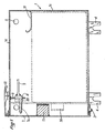
- la figure 1 présente une vue en coupe longitudinale le boîtier fermé avec indication en pointillé de l'emplacement de la batterie et de son support logés à l'intérieur,
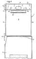
- la figure 2 une vue de face du boîtier ouvert,
- la figure 3 une vue de côté du support dans lequel est placée la batterie,
- la figure 4 une vue de face du support.
- Le boîtier 1 se présente sous forme d'une boîte dont les côtés latéraux sont désignés 1 a et 1 b, la paroi arrière 1c et la paroi supérieure 1d et pourvue d'une porte 2 articulée par des charnières 3. Le boîtier est pourvu de pieds 4 servant à le fixer au voisinage de l'installation à alimenter.
- Un orifice 5 percé dans la paroi latérale 1 permet la sortie de fils vers l'appareillage à alimenter.
- A la paroi supérieure 1d est fixée à l'intérieur du boîtier une plaque 6 servant de support aux deux pions de centrage 7a et 7b fixés perpendiculairement à la face extérieure de la plaque symétriquement par rapport à son centre.
- La plaque 6 porte un connecteur mâle 8 dont les plots de contact ressortent sur la face extérieure de la plaque et sont destinés à être coiffés par le connecteur femelle 35 relié à la batterie.
- Du côté de la face intérieure de la plaque 6, le connecteur 8 est branché, par exemple par soudure, sur l'alimentation des appareils électronique au moyen du conducteur 9 qui traverse le boîtier vers l'extérieur en passant par l'orifice 5.
- A la paroi arrière 1c du boîtier est fixée une lame d'acier 10 dont l'extrémité est recourbée vers le haut, servant au calage vertical de la batterie.
- La porte 2 du boîtier porte du côté intérieur un butoir 11 revêtu de caoutchouc et dimensionné de façon à immobiliser horizontalement le support de batterie, lorsque la porte est verrouillée au moyen d'une sauterelle de verrouillage 12.
- La batterie 20 munie de bornes 21 est placée dans un support 30 comportant un fond 30a, deux côtés latéraux échancrés 30b, une face arrière 30c et une face avant 31 munie d'une poignée extérieure 36.
- A sa partie supérieure, la face avant 31 est percée de perforations de guidage 32a et 32b aux endroits correspondant à l'emplacement de pions de guidage 7a et 7b portés par la plaque 6 du boîtier, ainsi que d'un orifice 33 servant à faire passer les fils 34 reliés aux bornes 21 de la batterie pour les brancher sur le connecteur femelle 35 fixé à la face intérieure de la face avant 31 à la hauteur correspondant à l'emplacement du connecteur mâle 8 sur la plaque du boîtier.
- La mise en place de la batterie s'effectue de la façon suivante.
- On fixe ou on pose le boîtier 1 auprès de l'installation à alimenter, de façon à ce que la porte 2 soit accessible de l'extérieur. On branche les conducteurs 9 sur le connecteur mâle 8 et on les fait passer à travers l'orifice 5 vers l'installation à alimenter.
- On place la batterie à l'intérieur du support 30 et on connecte les fils 34 aux bornes 21 de la batterie et aux contacts du connecteur femelle 35 en les faisant passer de l'intérieur à l'extérieur du support.
- On saisit la poignée 36 du support et on glisse le support à l'intérieur du boîtier en le poussant à fond, de façon à insérer la batterie sous la lame de blocage 10. A cet instant, le connecteur femelle 35 coiffe le connecteur mâle 8 de la plaque 6 solidaire du boîtier et le jonction électrique est réalisée entre la batterie et l'installation à alimenter au moyen de fils 9.
- On referme la porte 2 en la verrouillant à l'aide de la sauterelle 12 de façon à ce que le butoir 11 maintienne avec serrage le support 30 contre la paroi arrière 1c du boîtier.
- Comme on comprend aisément, les avantages du système proposé sont principalement de deux sortes. D'une part, l'insertion du support avec la batterie au fond du boîtier réalise une parfaite connexion électrique et d'autre part, l'agencement intérieur du boîtier permet d'assurer l'immobilisation de la batterie à l'intérieur du boîtier à la suite de cette simple manoeuvre, de façon à permettre le placement de la batterie par exemple en position latérale ou la tête en bas.
Claims (4)
Priority Applications (1)
| Application Number | Priority Date | Filing Date | Title |
|---|---|---|---|
| AT86402475T ATE41268T1 (de) | 1985-11-12 | 1986-11-05 | Behaelter fuer wartungsfreie batterien mit immobilisierter fluessigkeit fuer die stromversorgung von selbstaendigen elektronischen apparaten. |
Applications Claiming Priority (2)
| Application Number | Priority Date | Filing Date | Title |
|---|---|---|---|
| FR8516645A FR2590079B1 (fr) | 1985-11-12 | 1985-11-12 | Boitier pour batteries sans entretien a liquide immobilise pour l'alimentation des appareillages electroniques autonomes |
| FR8516645 | 1985-11-12 |
Publications (2)
| Publication Number | Publication Date |
|---|---|
| EP0226488A1 EP0226488A1 (fr) | 1987-06-24 |
| EP0226488B1 true EP0226488B1 (fr) | 1989-03-08 |
Family
ID=9324687
Family Applications (1)
| Application Number | Title | Priority Date | Filing Date |
|---|---|---|---|
| EP86402475A Expired EP0226488B1 (fr) | 1985-11-12 | 1986-11-05 | Boitier pour batteries sans entretien à liquide immobilisé pour l'alimentation des appareillages électroniques autonomes |
Country Status (5)
| Country | Link |
|---|---|
| EP (1) | EP0226488B1 (fr) |
| AT (1) | ATE41268T1 (fr) |
| DE (1) | DE3662321D1 (fr) |
| ES (1) | ES2008035B3 (fr) |
| FR (1) | FR2590079B1 (fr) |
Families Citing this family (1)
| Publication number | Priority date | Publication date | Assignee | Title |
|---|---|---|---|---|
| CN102717804B (zh) * | 2012-07-03 | 2014-12-31 | 南车株洲电力机车有限公司 | 一种可防止误操作的城轨车辆蓄电池箱电池斗止挡结构 |
Family Cites Families (5)
| Publication number | Priority date | Publication date | Assignee | Title |
|---|---|---|---|---|
| BE493744A (fr) * | ||||
| US3956021A (en) * | 1974-05-09 | 1976-05-11 | Mikhail Stepanovich Tsygankov | Storage battery |
| GB2042242B (en) * | 1979-01-24 | 1982-12-08 | Hoppecke Zoellner Sohn Accu | Charging and discharging lead-acid battries |
| IT8053367V0 (it) * | 1980-07-07 | 1980-07-07 | Fiat Ricerche | Dispositivo per l'accumulazione e l'alimentazione di energia elettrica destinato ad essere installato su veicoli elettrici |
| JPS598266A (ja) * | 1982-07-06 | 1984-01-17 | Mitsubishi Electric Corp | 電気計器類の蓄電池取付装置 |
-
1985
- 1985-11-12 FR FR8516645A patent/FR2590079B1/fr not_active Expired
-
1986
- 1986-11-05 ES ES86402475T patent/ES2008035B3/es not_active Expired - Lifetime
- 1986-11-05 DE DE8686402475T patent/DE3662321D1/de not_active Expired
- 1986-11-05 AT AT86402475T patent/ATE41268T1/de not_active IP Right Cessation
- 1986-11-05 EP EP86402475A patent/EP0226488B1/fr not_active Expired
Non-Patent Citations (1)
| Title |
|---|
| PATENTS ABSTRACTS OF JAPAN, vol. 8, no. 88 (E-240)[1525], 21 avril 1984; & JP-A-59 8266 (MITSUBISHI DENKI K.K.) 17-01-1984 * |
Also Published As
| Publication number | Publication date |
|---|---|
| FR2590079A1 (fr) | 1987-05-15 |
| DE3662321D1 (en) | 1989-04-13 |
| ES2008035B3 (es) | 1992-10-16 |
| EP0226488A1 (fr) | 1987-06-24 |
| ATE41268T1 (de) | 1989-03-15 |
| FR2590079B1 (fr) | 1988-05-13 |
Similar Documents
| Publication | Publication Date | Title |
|---|---|---|
| FR2682224A1 (fr) | Dispositif de prise de charge pour vehicule a moteur electrique. | |
| FR2693842A1 (fr) | Dispositif de fixation de câbles électriques. | |
| FR2614752A1 (fr) | Socle d'appareil electrique pouvant prendre place dans une goulotte de passage de conducteurs | |
| EP0226488B1 (fr) | Boitier pour batteries sans entretien à liquide immobilisé pour l'alimentation des appareillages électroniques autonomes | |
| EP3782867B1 (fr) | Dispositif de connexion électrique pour un véhicule, véhicule et procédé d'installation associés | |
| EP2909657B1 (fr) | Borne de détection d'un réseau optiquement invisible, installation comprenant une telle borne de détection, et procédé de détection d'un réseau optiquement invisible | |
| JPH11215649A (ja) | 配電箱 | |
| EP0743728B1 (fr) | Coffret d'appareillage électrique | |
| EP0076183B1 (fr) | Dispositif de distribution électrique | |
| EP0552114A1 (fr) | Borne de raccordement multiple pour appareillage électrique modulaire | |
| CA1084602A (fr) | Retenteur de fiche raccord, fiches male et femelle, et fiche a plaque murale | |
| FR2612008A1 (fr) | Boitier isolant, de connexion electrique montable notamment dans un support de lampadaire | |
| FR2725319A1 (fr) | Support d'appareillage a rapporter sur une boite d'encastrement, et bloc de fixation propre a l'equipement d'un tel support d'appareillage | |
| FR2751831A1 (fr) | Commande de meuble electromotorisee | |
| FR2624662A1 (fr) | Boitier de connexion electrique | |
| FR2608850A1 (fr) | Boitier de raccordement pour cables electriques | |
| EP2981159B1 (fr) | Boîtier électronique présentant un socle | |
| FR2604033A1 (fr) | Mecanisme de connexion pour connecter un connecteur de cable a une douille | |
| EP1002345B1 (fr) | Boitier de connexion electrique | |
| FR2613544A1 (fr) | Dispositif pour prise electrique murale | |
| EP3174161A1 (fr) | Dispositif d'interconnexion d'un organe électrique à des paires de câbles électriques | |
| FR3138358A1 (fr) | Systeme de montage d’une batterie d’alimentation d’un moteur de vehicule automobile a propulsion electrique | |
| FR2605809A1 (fr) | Prise electrique de securite pour le raccordement momentane d'un appareil dote d'un bornier de type domino | |
| FR2602116A1 (fr) | Boitier de protection, principalement destine a recevoir les connexions et les appareillages d'alimentation des lampes d'eclairage public | |
| FR3027581A1 (fr) | Procede de montage d’un contacteur electrique de porte laterale coulissante. |
Legal Events
| Date | Code | Title | Description |
|---|---|---|---|
| PUAI | Public reference made under article 153(3) epc to a published international application that has entered the european phase |
Free format text: ORIGINAL CODE: 0009012 |
|
| 17P | Request for examination filed |
Effective date: 19861113 |
|
| AK | Designated contracting states |
Kind code of ref document: A1 Designated state(s): AT BE CH DE ES GB IT LI NL SE |
|
| 17Q | First examination report despatched |
Effective date: 19880818 |
|
| GRAA | (expected) grant |
Free format text: ORIGINAL CODE: 0009210 |
|
| AK | Designated contracting states |
Kind code of ref document: B1 Designated state(s): AT BE CH DE ES GB IT LI NL SE |
|
| PG25 | Lapsed in a contracting state [announced via postgrant information from national office to epo] |
Ref country code: SE Effective date: 19890308 Ref country code: AT Effective date: 19890308 |
|
| REF | Corresponds to: |
Ref document number: 41268 Country of ref document: AT Date of ref document: 19890315 Kind code of ref document: T |
|
| ITF | It: translation for a ep patent filed | ||
| GBT | Gb: translation of ep patent filed (gb section 77(6)(a)/1977) | ||
| REF | Corresponds to: |
Ref document number: 3662321 Country of ref document: DE Date of ref document: 19890413 |
|
| PG25 | Lapsed in a contracting state [announced via postgrant information from national office to epo] |
Ref country code: ES Free format text: LAPSE BECAUSE OF THE APPLICANT RENOUNCES Effective date: 19891106 |
|
| PG25 | Lapsed in a contracting state [announced via postgrant information from national office to epo] |
Ref country code: LI Effective date: 19891130 Ref country code: CH Effective date: 19891130 Ref country code: BE Effective date: 19891130 |
|
| PLBE | No opposition filed within time limit |
Free format text: ORIGINAL CODE: 0009261 |
|
| STAA | Information on the status of an ep patent application or granted ep patent |
Free format text: STATUS: NO OPPOSITION FILED WITHIN TIME LIMIT |
|
| 26N | No opposition filed | ||
| BERE | Be: lapsed |
Owner name: S.A. E.R.A.C. Effective date: 19891130 |
|
| PG25 | Lapsed in a contracting state [announced via postgrant information from national office to epo] |
Ref country code: NL Effective date: 19900601 |
|
| NLV4 | Nl: lapsed or anulled due to non-payment of the annual fee | ||
| REG | Reference to a national code |
Ref country code: CH Ref legal event code: PL |
|
| PG25 | Lapsed in a contracting state [announced via postgrant information from national office to epo] |
Ref country code: DE Effective date: 19900801 |
|
| PG25 | Lapsed in a contracting state [announced via postgrant information from national office to epo] |
Ref country code: GB Effective date: 19901105 |
|
| GBPC | Gb: european patent ceased through non-payment of renewal fee | ||
| REG | Reference to a national code |
Ref country code: ES Ref legal event code: FD2A Effective date: 20010402 |
|
| PG25 | Lapsed in a contracting state [announced via postgrant information from national office to epo] |
Ref country code: IT Free format text: LAPSE BECAUSE OF NON-PAYMENT OF DUE FEES;WARNING: LAPSES OF ITALIAN PATENTS WITH EFFECTIVE DATE BEFORE 2007 MAY HAVE OCCURRED AT ANY TIME BEFORE 2007. THE CORRECT EFFECTIVE DATE MAY BE DIFFERENT FROM THE ONE RECORDED. Effective date: 20051105 |