EP0226060A2 - Equipment for transport and handling of containers and other larger load carriers - Google Patents
Equipment for transport and handling of containers and other larger load carriers Download PDFInfo
- Publication number
- EP0226060A2 EP0226060A2 EP86116035A EP86116035A EP0226060A2 EP 0226060 A2 EP0226060 A2 EP 0226060A2 EP 86116035 A EP86116035 A EP 86116035A EP 86116035 A EP86116035 A EP 86116035A EP 0226060 A2 EP0226060 A2 EP 0226060A2
- Authority
- EP
- European Patent Office
- Prior art keywords
- load
- stand
- fitted
- carrying frame
- changer
- Prior art date
- Legal status (The legal status is an assumption and is not a legal conclusion. Google has not performed a legal analysis and makes no representation as to the accuracy of the status listed.)
- Granted
Links
Images


Classifications
-
- B—PERFORMING OPERATIONS; TRANSPORTING
- B60—VEHICLES IN GENERAL
- B60S—SERVICING, CLEANING, REPAIRING, SUPPORTING, LIFTING, OR MANOEUVRING OF VEHICLES, NOT OTHERWISE PROVIDED FOR
- B60S9/00—Ground-engaging vehicle fittings for supporting, lifting, or manoeuvring the vehicle, wholly or in part, e.g. built-in jacks
- B60S9/02—Ground-engaging vehicle fittings for supporting, lifting, or manoeuvring the vehicle, wholly or in part, e.g. built-in jacks for only lifting or supporting
- B60S9/04—Ground-engaging vehicle fittings for supporting, lifting, or manoeuvring the vehicle, wholly or in part, e.g. built-in jacks for only lifting or supporting mechanically
-
- A—HUMAN NECESSITIES
- A01—AGRICULTURE; FORESTRY; ANIMAL HUSBANDRY; HUNTING; TRAPPING; FISHING
- A01D—HARVESTING; MOWING
- A01D90/00—Vehicles for carrying harvested crops with means for selfloading or unloading
- A01D90/12—Vehicles for carrying harvested crops with means for selfloading or unloading with additional devices or implements
-
- B—PERFORMING OPERATIONS; TRANSPORTING
- B60—VEHICLES IN GENERAL
- B60D—VEHICLE CONNECTIONS
- B60D1/00—Traction couplings; Hitches; Draw-gear; Towing devices
- B60D1/14—Draw-gear or towing devices characterised by their type
- B60D1/143—Draw-gear or towing devices characterised by their type characterised by the mounting of the draw-gear on the towed vehicle
Abstract
Description
- The invention concerns equipment for transport and handling of containers and other larger load carriers which, together with a load carrying frame, forms a load unit designed so as to be able to be placed on a load changer on a first vehicle which is fitted with devices for manoeuvring of the load unit when this is to be placed on or unloaded from the load changer, with this load carrying frame being fitted with an upward-pointing stand (pillar) at the front end with coupling mechanism for coupling of the said manoeuvring devices with the stand.
- Whole crop harvesting is a new and old method for gathering in all valuable components of harvest crops, i.e. not only seed corn but also straw, blades and husks. In its modern form this technique entails the whole plant except the root system and a short stubble being cut directly on the field by the harvesting machine. The cut produce is collected in a container which is carried by the harvesting machine. When the container is full it is transported to a centre, after which the cut produce is separated into different components or treated in another way. So that the new technique's advantages may be able to be utilised in an effective manner it is essential that all steps in the handling system can be carried out in a rational way. This entails among other things that all forms of transport must be able to be carried out rationally and that load transfer must be able to be avoided as far as possible. The latter condition has not been able to be solved in a satisfactory way with the aid of known technology.
- An aim of the invention is to offer equipment which solves the abovementioned problems connected with whole crop harvesting better than known equipment, wether it is a question of grain crops or other crops. The application of the invention is not, however, limited to this sphere, but can with advantage be used also in many other fields where there is a requirement to change between carried and towed transportation. Examples of such requirements are to be found in forestry, peat handling, manufacturing, industry and many other fields.
- According to the invention the load unit can be converted to a trailer which can be coupled directly to a tractor or other towing vehicle for transport of the load carrier between a loading place, for example a harvest field, and an emptying place, for example a receiving centre or similar. This conversion capability can be achieved through the fact that the load carrying frame is longer than the load changer, so that the load carrying frame projects with a part at the rear end beyond the rear end of the load changer, that the aforesaid rear end part on the load carrying frame is fitted with at least one pair of wheels, and through the fact that the aforesaid stand at the front end of the load unit can be swung down, when the load unit is unloaded, through rotation of a horizontal member, so that the dropped column can serve as a drawbar when the load unit is converted into a trailer.
- Preferably the stand has an L-shaped profile, while the aforesaid member forming a coupling between the end of the short shank of the L and the front end of the main part of the load carrying frame. Further it is advisable to have one or more ground supports fitted to the upper part of the stand, more closely on the side which, in relation to the L shape, is turned leftwards from the vertical shank of the L. These ground supports function when the load unit is converted to a trailer and the towing vehicle is uncoupled. The ground supports can have the form of feet or wheels.
- The power sources for converting the load unit to a trailer and vice versa comprise a pair of hydraulic cylinders which are fitted on the load unit in order to produce the rotational movements around the horizontal axis of rotation of the aforesaid member.
- Further characteristics and advantages of the invention will become clear from the patent claims and from the following description of a preferred embodiment.
- In the following description of a preferred embodiment reference will be made to the enclosed drawings, of which
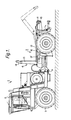
- Fig. 1 is a side view of a vehicle, called the first vehicle, which is fitted in a manner which is in itself known with a load changer and so called projection for manoeuvring of a load unit,
- Fig. 2 shows the same vehicle as in Fig. 1 fitted with a header and a load unit with the container belonging to it placed on the load changer,
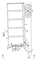
- Fig. 3 is a side view of the load unit on a larger scale,
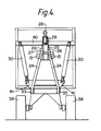
- Fig. 4 is an end view IV-IV in Fig. 3, and
- Fig. 5 is a side view, which shows how the load unit converted to a trailer can be coupled to a tractor.
- In Figs. 1 and 2 a first vehicle is designated with the numeral 1. This consists of a front part with driver's
cab 5 and a rear part with load changer 2. Between the two parts there is an articulatedframe steering hinge 9. The front part has a pair offront wheels 3, and the rear part has a pair ofrear wheels 4. The basic construction of the vehicle 1 is known in the art and does not constitute any part of the invention. Its rear end has been designated 10. - At the
rear end 10 of the load changer 2 there are "roll-on roll-off" rollers, in a way that is in itself well known, for unloading and loading of aload unit 7, Fig. 2 and Fig. 3, consisting of acontainer 8 and aload carrying frame 20. Thecontainer 8 and the load carrying frame are attached to each other by welding, - On the load changer 2 there is also a projection 6 for manoeuvring of the
load unit 7 in connection with unloading and loading. The projection 6 consists, in a well known manner, of an angled beam construction with a straightfirst part 12, which is horizontal in the rest position, and another angled part which includes avertical pillar 13, which is terminated in ahook 14, and ahorizontal part 13′, which is telescopically movable in thefirst part 12. Thefirst part 12 is connected at its rear end to the load changer 2 through a horizontal manoeuvre arm shaft. In the load changer 2 two parallel firsthydraulic cylinders 16 are fitted, one on each side of the first part of thebeam 12, in order to be able to swing the projection 6 through rotation about the said shaft in order to drop the projection 6 backwards to the position marked with a dotted line in Fig. 1. In addition there are other hydraulic cylinders - not shown - in order to project thevertical pillar 13 forwards and backwards in relation to the load changer, with thehorizontal part 13′ moving telescopically in the first namedpart 12 in connection with unloading and loading of theload unit 7. - In Fig. 2 it is shown how the vehicle 1 functions as a combined implement carrier and load carrier. The front part has been fitted with a
header 17 and achopper 18. The chopped harvest crop is transported with the aid of a blower and aduct 19 to thecontainer 8. The vehicle 1 also contains a hydraulic motor to operate the system's various hydraulic components. - The above described construction belongs to well known technology. The new element resides in the design of the
load unit 7. Theload unit 7 comprises on the one hand the abovementionedload carrying frame 20, which is fixed by welding to thecontainer 8, and on the other hand a stand (pillar) 21, which is shaped like an L, whose right-hand arm at its right-hand end is pivotally connected to the front end of theload carrying frame 20 by ahorizontal hinge 22. - The rear main section of the
load changer frame 20 consists in the well known manner of longitudinal parallel side beams and crossbeams welded together into aframework 31, which in its turn is fixed by welding to thecontainer 8. Thestand 21 includes a pair of beams, which have, as has already been mentioned, from the side the shape of an L. The two shorter, parallell arms, which at their outer ends are pivotally connected to theframework 31 by the pivot 22 (turning axis), have been designated 23 and the two longer arms have been designated 24, Fig. 4. The knee bend in the angle between the twoarms longer arms 24 approach each other at the outer ends, where they are joined together by awelded plate construction 25 containing a pair ofside plates 26. Between these twoside plates 26 there extends alink 27 arranged to work in conjunction with thehook 14 on the projection 6. In addition there is aneye 28 attached to anend plate 29 on theplate construction 25. The twolonger arms 24 both also feature on the outside a pair of supportingfeet 15 withlegs 39, which are pivotally connected with the twoshanks 24. - The
load unit 7 is substantially longer than the load changer 2. In the rear part of the load unit, which projects beyond therear edge 10 of the load changer 2 when theload unit 7 is mounted on the load changer 2, there are two pairs ofbogie wheels 38, which hang free in the air when theload unit 7 with thecontainer 8 is loaded on the vehicle 1. - The equipment described can be handled in the following manner. Suppose that the
load unit 7 with thecontainer 8 is loaded on the load changer 2, and that thecontainer 8 has been filled with harvest produce and is to be transported to a receiving centre. Theload unit 7 with the container is unloaded from the load changer 2 with the aid of the projection 6 and the hydraulic cylinders belonging to it in the well known manner. The unloaded unit is thus standing inclined forwards with the back pair ofbogie wheels 38 and theknee bend 33 resting on the ground. With the aid of a pair of double-actinghydraulic cylinders 30 fitted between ahorizontal beam 40 on the container's front end and a pair of fasteninglugs 41 on the outside of the arms 24 a bit above theknee bend 33 thestand 21 swings forwards and downwards through rotation about theturning axis 22. Theknee bend 33 is then pressed harder against the ground after thearms bogie wheels 38 rolls slightly forwards. The ground supports 15 soon come to reach the ground. Through continued rotation about theaxis 22 thehydraulic cylinder 30 continues to project thestand 21 away from itself and press thefeet 15 against the ground, so that the knee bends 33 leave the ground until theload carrying frame 20 has assumed a substantially horizontal position. Theload changer frame 20 has now been converted into atruck 7′ or trailer consisting of acontainer 8 on theframework 31 which forms the chassis of thetruck 7′. At the rear there are thewheels 38 and at the front adrawbar 21′, formed by the swung-down pillar 21. Thetruck 7′ can be coupled to atractor 43 by means of theeye 28 at the end of thedrawbar 21′. The unit can then be moved to the receiving centre or similar, where the container is emptied. Thetractor 43 with thetruck 7′ can then be driven back, thetruck 7′ is uncoupled and converted to aload unit 7 through return of thedrawbar 21′ so that instead it forms a stand (pillar) 21 withattachment 27 for thehook 14 on the projection 6 etc.
Claims (5)
characterised by the fact that the load carrying frame (20) is longer than the load changer (2), so that the load carrying frame projects with a rear end part beyond the rear end (10) of the load changer, that the aforesaid rear end part of the load carrying frame is fitted with at least one pair of wheels (38), and that the aforesaid stand (21), when the load unit is unloaded, can be swung down through rotation about a horizontal axis (22) for converting the load unit (7) into a trailer (7′), with the swung-down stand being able to act as a drawbar (21′) on the trailer (7′).
Priority Applications (1)
| Application Number | Priority Date | Filing Date | Title |
|---|---|---|---|
| AT86116035T ATE49929T1 (en) | 1985-12-13 | 1986-11-20 | EQUIPMENT FOR TRANSPORTATION AND HANDLING OF CONTAINERS AND OTHER LARGER LOAD CARRIERS. |
Applications Claiming Priority (2)
| Application Number | Priority Date | Filing Date | Title |
|---|---|---|---|
| SE8505906A SE452730B (en) | 1985-12-13 | 1985-12-13 | EQUIPMENT FOR TRANSPORT AND HANDLING OF CONTAINERS AND OTHER LARGE LOADERS |
| SE8505906 | 1985-12-13 |
Publications (3)
| Publication Number | Publication Date |
|---|---|
| EP0226060A2 true EP0226060A2 (en) | 1987-06-24 |
| EP0226060A3 EP0226060A3 (en) | 1987-11-19 |
| EP0226060B1 EP0226060B1 (en) | 1990-01-31 |
Family
ID=20362455
Family Applications (1)
| Application Number | Title | Priority Date | Filing Date |
|---|---|---|---|
| EP86116035A Expired - Lifetime EP0226060B1 (en) | 1985-12-13 | 1986-11-20 | Equipment for transport and handling of containers and other larger load carriers |
Country Status (5)
| Country | Link |
|---|---|
| EP (1) | EP0226060B1 (en) |
| AT (1) | ATE49929T1 (en) |
| DE (1) | DE3668587D1 (en) |
| ES (1) | ES2013705B3 (en) |
| SE (1) | SE452730B (en) |
Cited By (5)
| Publication number | Priority date | Publication date | Assignee | Title |
|---|---|---|---|---|
| AU620865B2 (en) * | 1988-04-28 | 1992-02-27 | Siemens Aktiengesellschaft | Optical waveguide |
| FR2697208A1 (en) * | 1992-10-27 | 1994-04-29 | Diebolt Remy | Chassis extension, e.g. for attachment of trailers or bogies to heavy vehicles - has towing attachment, with telescopic bar which is pivoted to this attachment by pin and which is controlled by mechanism of jacks and cables |
| NL9302072A (en) * | 1993-11-30 | 1995-06-16 | Alkas B V Wageningen | Triangle and assembly comprising triangle and carriage(s) |
| EP1298026A1 (en) * | 2001-09-26 | 2003-04-02 | Coutier Industrie | Trailer hitch and means for manoeuvring a carriage |
| FR3012404A1 (en) * | 2013-10-25 | 2015-05-01 | Rio Tinto Alcan Int Ltd | HANDLING DEVICE FOR HANDLING A LOAD IN AN ELECTROLYSIS FACTORY, ALUMINUM COMPRISING THIS DEVICE AND SUPPORT PLATFORM FOR IMPLEMENTING SAID DEVICE |
Citations (4)
| Publication number | Priority date | Publication date | Assignee | Title |
|---|---|---|---|---|
| US3057499A (en) * | 1961-01-11 | 1962-10-09 | Young Spring & Wire Corp | Trailer tractor for rail-highway freight transfer equipment |
| DE1954743U (en) * | 1966-12-13 | 1967-02-02 | Herbert Vidal & Co Karosserie | SINGLE OR MULTI-AXIS ROAD TRANSPORT DEVICE FOR THE TRANSPORTATION OF CONTAINERS IN CONNECTION WITH A SEMI-TRACTOR. |
| DE2119420A1 (en) * | 1970-04-21 | 1971-10-28 | Fiat S.P.A., Turin (Italien) | Articulated truck |
| US4243353A (en) * | 1979-02-14 | 1981-01-06 | Reed Floyd W | Cotton module transport apparatus |
-
1985
- 1985-12-13 SE SE8505906A patent/SE452730B/en not_active IP Right Cessation
-
1986
- 1986-11-20 AT AT86116035T patent/ATE49929T1/en not_active IP Right Cessation
- 1986-11-20 DE DE8686116035T patent/DE3668587D1/en not_active Expired - Lifetime
- 1986-11-20 ES ES86116035T patent/ES2013705B3/en not_active Expired - Lifetime
- 1986-11-20 EP EP86116035A patent/EP0226060B1/en not_active Expired - Lifetime
Patent Citations (4)
| Publication number | Priority date | Publication date | Assignee | Title |
|---|---|---|---|---|
| US3057499A (en) * | 1961-01-11 | 1962-10-09 | Young Spring & Wire Corp | Trailer tractor for rail-highway freight transfer equipment |
| DE1954743U (en) * | 1966-12-13 | 1967-02-02 | Herbert Vidal & Co Karosserie | SINGLE OR MULTI-AXIS ROAD TRANSPORT DEVICE FOR THE TRANSPORTATION OF CONTAINERS IN CONNECTION WITH A SEMI-TRACTOR. |
| DE2119420A1 (en) * | 1970-04-21 | 1971-10-28 | Fiat S.P.A., Turin (Italien) | Articulated truck |
| US4243353A (en) * | 1979-02-14 | 1981-01-06 | Reed Floyd W | Cotton module transport apparatus |
Cited By (5)
| Publication number | Priority date | Publication date | Assignee | Title |
|---|---|---|---|---|
| AU620865B2 (en) * | 1988-04-28 | 1992-02-27 | Siemens Aktiengesellschaft | Optical waveguide |
| FR2697208A1 (en) * | 1992-10-27 | 1994-04-29 | Diebolt Remy | Chassis extension, e.g. for attachment of trailers or bogies to heavy vehicles - has towing attachment, with telescopic bar which is pivoted to this attachment by pin and which is controlled by mechanism of jacks and cables |
| NL9302072A (en) * | 1993-11-30 | 1995-06-16 | Alkas B V Wageningen | Triangle and assembly comprising triangle and carriage(s) |
| EP1298026A1 (en) * | 2001-09-26 | 2003-04-02 | Coutier Industrie | Trailer hitch and means for manoeuvring a carriage |
| FR3012404A1 (en) * | 2013-10-25 | 2015-05-01 | Rio Tinto Alcan Int Ltd | HANDLING DEVICE FOR HANDLING A LOAD IN AN ELECTROLYSIS FACTORY, ALUMINUM COMPRISING THIS DEVICE AND SUPPORT PLATFORM FOR IMPLEMENTING SAID DEVICE |
Also Published As
| Publication number | Publication date |
|---|---|
| SE8505906D0 (en) | 1985-12-13 |
| EP0226060A3 (en) | 1987-11-19 |
| ES2013705B3 (en) | 1990-06-01 |
| DE3668587D1 (en) | 1990-03-08 |
| ATE49929T1 (en) | 1990-02-15 |
| EP0226060B1 (en) | 1990-01-31 |
| SE452730B (en) | 1987-12-14 |
| SE8505906L (en) | 1987-06-14 |
Similar Documents
| Publication | Publication Date | Title |
|---|---|---|
| US8567169B2 (en) | Agriculture bale accumulator | |
| US3800966A (en) | Loader crane for gooseneck trailer | |
| US7673439B2 (en) | Agricultural machine for swathing products lying on the ground | |
| US4564325A (en) | Flush-mounted round bale mover for truck beds | |
| US5401050A (en) | Machinery transport trailer | |
| US7100351B2 (en) | Foldable hay rake | |
| US4348143A (en) | Large round hay bale mover | |
| US5090720A (en) | Transporting system and method for using same | |
| US4621776A (en) | Round bale handler | |
| US5361569A (en) | Harvester header transport apparatus | |
| US4579497A (en) | Stowable round bale hauler | |
| US4773806A (en) | Agricultural vehicle for transporting and feeding hay | |
| US5362189A (en) | Bale handling carrier | |
| US4290733A (en) | Forage stack mover | |
| US5165836A (en) | Round bale hauler | |
| US5257885A (en) | Round bale windrower | |
| EP0226060B1 (en) | Equipment for transport and handling of containers and other larger load carriers | |
| US2606417A (en) | Reversible implement and coupling therefor | |
| US4364700A (en) | Bale-handling apparatus | |
| GB2026429A (en) | Load lifting and transporting vehicle | |
| US3536339A (en) | Vertically adjustable wheeled trailer | |
| US4126234A (en) | Large cylindrical bale transporter | |
| US5580208A (en) | Tractor three-point hitch mounted transporter | |
| US5964078A (en) | Multiple implement tow bar assembly | |
| CA2302217C (en) | Agricultural bale accumulator |
Legal Events
| Date | Code | Title | Description |
|---|---|---|---|
| PUAI | Public reference made under article 153(3) epc to a published international application that has entered the european phase |
Free format text: ORIGINAL CODE: 0009012 |
|
| AK | Designated contracting states |
Kind code of ref document: A2 Designated state(s): AT BE CH DE ES FR GB GR IT LI LU NL SE |
|
| PUAL | Search report despatched |
Free format text: ORIGINAL CODE: 0009013 |
|
| AK | Designated contracting states |
Kind code of ref document: A3 Designated state(s): AT BE CH DE ES FR GB GR IT LI LU NL SE |
|
| 17P | Request for examination filed |
Effective date: 19880401 |
|
| 17Q | First examination report despatched |
Effective date: 19890421 |
|
| GRAA | (expected) grant |
Free format text: ORIGINAL CODE: 0009210 |
|
| AK | Designated contracting states |
Kind code of ref document: B1 Designated state(s): AT BE CH DE ES FR GB GR IT LI LU NL SE |
|
| PG25 | Lapsed in a contracting state [announced via postgrant information from national office to epo] |
Ref country code: SE Effective date: 19900131 Ref country code: LI Effective date: 19900131 Ref country code: GR Free format text: LAPSE BECAUSE OF FAILURE TO SUBMIT A TRANSLATION OF THE DESCRIPTION OR TO PAY THE FEE WITHIN THE PRESCRIBED TIME-LIMIT Effective date: 19900131 Ref country code: CH Effective date: 19900131 Ref country code: AT Effective date: 19900131 |
|
| REF | Corresponds to: |
Ref document number: 49929 Country of ref document: AT Date of ref document: 19900215 Kind code of ref document: T |
|
| REF | Corresponds to: |
Ref document number: 3668587 Country of ref document: DE Date of ref document: 19900308 |
|
| RAP2 | Party data changed (patent owner data changed or rights of a patent transferred) |
Owner name: DE ROTTERDAMSCHE DROOGDOK MAATSCHAPPIJ B.V. |
|
| REG | Reference to a national code |
Ref country code: CH Ref legal event code: PUE Owner name: DE ROTTERDAMSCHE DROOGDOK MAATSCHAPPIJ B.V. |
|
| ITF | It: translation for a ep patent filed |
Owner name: STUDIO TORTA SOCIETA' SEMPLICE |
|
| ET | Fr: translation filed | ||
| REG | Reference to a national code |
Ref country code: CH Ref legal event code: PL |
|
| PLBE | No opposition filed within time limit |
Free format text: ORIGINAL CODE: 0009261 |
|
| STAA | Information on the status of an ep patent application or granted ep patent |
Free format text: STATUS: NO OPPOSITION FILED WITHIN TIME LIMIT |
|
| PG25 | Lapsed in a contracting state [announced via postgrant information from national office to epo] |
Ref country code: LU Free format text: LAPSE BECAUSE OF NON-PAYMENT OF DUE FEES Effective date: 19901130 |
|
| 26N | No opposition filed | ||
| ITTA | It: last paid annual fee | ||
| PGFP | Annual fee paid to national office [announced via postgrant information from national office to epo] |
Ref country code: GB Payment date: 19931110 Year of fee payment: 8 Ref country code: FR Payment date: 19931110 Year of fee payment: 8 |
|
| PGFP | Annual fee paid to national office [announced via postgrant information from national office to epo] |
Ref country code: DE Payment date: 19931123 Year of fee payment: 8 |
|
| PGFP | Annual fee paid to national office [announced via postgrant information from national office to epo] |
Ref country code: NL Payment date: 19931130 Year of fee payment: 8 Ref country code: ES Payment date: 19931130 Year of fee payment: 8 |
|
| PGFP | Annual fee paid to national office [announced via postgrant information from national office to epo] |
Ref country code: BE Payment date: 19940105 Year of fee payment: 8 |
|
| PG25 | Lapsed in a contracting state [announced via postgrant information from national office to epo] |
Ref country code: GB Effective date: 19941120 |
|
| PG25 | Lapsed in a contracting state [announced via postgrant information from national office to epo] |
Ref country code: ES Free format text: LAPSE BECAUSE OF THE APPLICANT RENOUNCES Effective date: 19941121 |
|
| PG25 | Lapsed in a contracting state [announced via postgrant information from national office to epo] |
Ref country code: BE Effective date: 19941130 |
|
| BERE | Be: lapsed |
Owner name: DE ROTTERDAMSCHE DROOGDOK MAATSCHAPPIJ B.V. Effective date: 19941130 |
|
| PG25 | Lapsed in a contracting state [announced via postgrant information from national office to epo] |
Ref country code: NL Effective date: 19950601 |
|
| NLV4 | Nl: lapsed or anulled due to non-payment of the annual fee | ||
| GBPC | Gb: european patent ceased through non-payment of renewal fee |
Effective date: 19941120 |
|
| PG25 | Lapsed in a contracting state [announced via postgrant information from national office to epo] |
Ref country code: FR Effective date: 19950731 |
|
| PG25 | Lapsed in a contracting state [announced via postgrant information from national office to epo] |
Ref country code: DE Effective date: 19950801 |
|
| REG | Reference to a national code |
Ref country code: FR Ref legal event code: ST |
|
| REG | Reference to a national code |
Ref country code: ES Ref legal event code: FD2A Effective date: 20010402 |
|
| PG25 | Lapsed in a contracting state [announced via postgrant information from national office to epo] |
Ref country code: IT Free format text: LAPSE BECAUSE OF NON-PAYMENT OF DUE FEES Effective date: 20051120 |