EP0225815B1 - Tool for closing the production string of a well - Google Patents
Tool for closing the production string of a well Download PDFInfo
- Publication number
- EP0225815B1 EP0225815B1 EP86402298A EP86402298A EP0225815B1 EP 0225815 B1 EP0225815 B1 EP 0225815B1 EP 86402298 A EP86402298 A EP 86402298A EP 86402298 A EP86402298 A EP 86402298A EP 0225815 B1 EP0225815 B1 EP 0225815B1
- Authority
- EP
- European Patent Office
- Prior art keywords
- valve
- piston
- assembly
- tool
- tool according
- Prior art date
- Legal status (The legal status is an assumption and is not a legal conclusion. Google has not performed a legal analysis and makes no representation as to the accuracy of the status listed.)
- Expired - Lifetime
Links
- 238000004519 manufacturing process Methods 0.000 title description 19
- 239000012530 fluid Substances 0.000 claims description 21
- 230000000694 effects Effects 0.000 claims description 13
- 238000005192 partition Methods 0.000 claims description 9
- 230000002093 peripheral effect Effects 0.000 claims description 5
- 238000006073 displacement reaction Methods 0.000 claims description 4
- 239000007788 liquid Substances 0.000 claims description 4
- 238000011144 upstream manufacturing Methods 0.000 claims description 3
- 230000000712 assembly Effects 0.000 claims description 2
- 238000000429 assembly Methods 0.000 claims description 2
- 230000000295 complement effect Effects 0.000 claims 1
- 210000002445 nipple Anatomy 0.000 claims 1
- 238000007789 sealing Methods 0.000 description 4
- 210000000078 claw Anatomy 0.000 description 3
- 230000005540 biological transmission Effects 0.000 description 2
- 239000004215 Carbon black (E152) Substances 0.000 description 1
- 230000003321 amplification Effects 0.000 description 1
- 230000004323 axial length Effects 0.000 description 1
- 230000006835 compression Effects 0.000 description 1
- 238000007906 compression Methods 0.000 description 1
- 230000001419 dependent effect Effects 0.000 description 1
- 229930195733 hydrocarbon Natural products 0.000 description 1
- 150000002430 hydrocarbons Chemical class 0.000 description 1
- 238000005259 measurement Methods 0.000 description 1
- 230000005226 mechanical processes and functions Effects 0.000 description 1
- 238000003199 nucleic acid amplification method Methods 0.000 description 1
- 239000000725 suspension Substances 0.000 description 1
Images


Classifications
-
- E—FIXED CONSTRUCTIONS
- E21—EARTH DRILLING; MINING
- E21B—EARTH DRILLING, e.g. DEEP DRILLING; OBTAINING OIL, GAS, WATER, SOLUBLE OR MELTABLE MATERIALS OR A SLURRY OF MINERALS FROM WELLS
- E21B23/00—Apparatus for displacing, setting, locking, releasing, or removing tools, packers or the like in the boreholes or wells
- E21B23/004—Indexing systems for guiding relative movement between telescoping parts of downhole tools
- E21B23/006—"J-slot" systems, i.e. lug and slot indexing mechanisms
-
- E—FIXED CONSTRUCTIONS
- E21—EARTH DRILLING; MINING
- E21B—EARTH DRILLING, e.g. DEEP DRILLING; OBTAINING OIL, GAS, WATER, SOLUBLE OR MELTABLE MATERIALS OR A SLURRY OF MINERALS FROM WELLS
- E21B34/00—Valve arrangements for boreholes or wells
- E21B34/06—Valve arrangements for boreholes or wells in wells
- E21B34/14—Valve arrangements for boreholes or wells in wells operated by movement of tools, e.g. sleeve valves operated by pistons or wire line tools
-
- F—MECHANICAL ENGINEERING; LIGHTING; HEATING; WEAPONS; BLASTING
- F15—FLUID-PRESSURE ACTUATORS; HYDRAULICS OR PNEUMATICS IN GENERAL
- F15B—SYSTEMS ACTING BY MEANS OF FLUIDS IN GENERAL; FLUID-PRESSURE ACTUATORS, e.g. SERVOMOTORS; DETAILS OF FLUID-PRESSURE SYSTEMS, NOT OTHERWISE PROVIDED FOR
- F15B11/00—Servomotor systems without provision for follow-up action; Circuits therefor
- F15B11/02—Systems essentially incorporating special features for controlling the speed or actuating force of an output member
- F15B11/028—Systems essentially incorporating special features for controlling the speed or actuating force of an output member for controlling the actuating force
- F15B11/032—Systems essentially incorporating special features for controlling the speed or actuating force of an output member for controlling the actuating force by means of fluid-pressure converters
- F15B11/0325—Systems essentially incorporating special features for controlling the speed or actuating force of an output member for controlling the actuating force by means of fluid-pressure converters the fluid-pressure converter increasing the working force after an approach stroke
-
- F—MECHANICAL ENGINEERING; LIGHTING; HEATING; WEAPONS; BLASTING
- F15—FLUID-PRESSURE ACTUATORS; HYDRAULICS OR PNEUMATICS IN GENERAL
- F15B—SYSTEMS ACTING BY MEANS OF FLUIDS IN GENERAL; FLUID-PRESSURE ACTUATORS, e.g. SERVOMOTORS; DETAILS OF FLUID-PRESSURE SYSTEMS, NOT OTHERWISE PROVIDED FOR
- F15B2211/00—Circuits for servomotor systems
- F15B2211/50—Pressure control
- F15B2211/505—Pressure control characterised by the type of pressure control means
- F15B2211/50509—Pressure control characterised by the type of pressure control means the pressure control means controlling a pressure upstream of the pressure control means
-
- F—MECHANICAL ENGINEERING; LIGHTING; HEATING; WEAPONS; BLASTING
- F15—FLUID-PRESSURE ACTUATORS; HYDRAULICS OR PNEUMATICS IN GENERAL
- F15B—SYSTEMS ACTING BY MEANS OF FLUIDS IN GENERAL; FLUID-PRESSURE ACTUATORS, e.g. SERVOMOTORS; DETAILS OF FLUID-PRESSURE SYSTEMS, NOT OTHERWISE PROVIDED FOR
- F15B2211/00—Circuits for servomotor systems
- F15B2211/50—Pressure control
- F15B2211/55—Pressure control for limiting a pressure up to a maximum pressure, e.g. by using a pressure relief valve
Definitions
- the present invention relates to a tool for closing the production column of a well containing a pressurized fluid, this tool, designed to be temporarily fixed inside the production column or to be an integral part of it.
- -ci comprising a valve which can be actuated to close or open the production column in the passage of the fluid from the well.
- one of the main tests for determining the production capacity of a hydrocarbon well consists in stopping production using a valve and recording the pressure variations resulting from the closing of the well.
- US-A-4 252 188 corresponds to the preamble of claim 1 and describes an actuating device for controlling the operation of an intake valve installed in a well. It comprises a first annular piston which is moved upwards under the action of the pressure established between the annular space of the well and the production column. During this movement, the first piston, by compressing a spring, lowers by means of a double-chamber hydraulic transmission a second piston which controls the opening of the valve.
- the subject of the invention is a sealing tool which can be installed in the production column of a well for the duration of the tests carried out on the well, the valve of this tool being easy to maneuver despite the considerable pressure which can reign in the well and which opposes the opening of the valve after it has been closed.
- the tool according to the invention comprises respective chambers of variable volume, of different section, communicating with one another and filled with a hydraulic liquid which is preferably confined therein;
- the piston of the first assembly acts on the valve in the direction of its opening under the effect of the pressure of the hydraulic fluid to which it is subjected, this piston offering an inner face, in contact with the hydraulic fluid, the surface of which is greater on the surface of the inner face of the piston of the second set.
- the piston of the second set slides in the corresponding cylinder in the direction of the longitudinal axis of the tool and its arrangement is such that, when it is stressed upwards by a cable which is attached to it, it causes a reduction in the volume of the chamber of said assembly. Consequently, by applying a tensile force to the cable which goes up to the surface inside the production column, a multiplier effect is obtained on this force which makes it possible to control the opening of the valve despite the pressure of the well fluids that oppose this opening.
- the piston of the second set should offer an external surface which is subjected to the pressure of the well upstream of the valve and which is greater than the surface of the internal face of said piston. Thanks to this arrangement, the valve in closed position receives from the piston of the first assembly, subjected to the pressure of the hydraulic fluid which is higher than the ambient pressure prevailing in the well where the tool is located, a force in the direction of its opening, which is deducted from the force that the valve receives directly from the pressurized fluid from the well, which tends to keep it closed.
- valve is relieved and its opening is obtained by applying a reduced control force compared to the force which would be necessary in the absence of said hydraulic mechanism, any measure of pressure equalization on the part and other of the valve prior to its opening becoming superfluous.
- This effect is combined with the aforementioned force multiplier effect and leads to a further reduction in the force to be applied to obtain the opening of the valve.
- valve will normally consist of a valve and a conjugate seat, this valve being integral with the piston of the first assembly.
- the structure of the hydraulic mechanism is given a coaxial configuration. More specifically, it can be provided that the valve flap is integral with a cylindrical sleeve whose axis is parallel to the direction of movement of the valve and which externally carries the piston of the first assembly in the form of a sliding annular piston in a fixed cylindrical sleeve, forming the side wall of the cylinder of the first set and closed by a transverse partition which is situated between the valve and the piston and through which the sleeve integral with the valve can slide in leaktight manner, the latter sleeve forming the side wall of the chamber of the second assembly, which communicates with the chamber of the first assembly by at least one orifice drilled in said wall, and in which the piston of the second assembly slides, this piston being integral with an actuating rod which can slide tightly through the valve and to which is attached a cable such as the aforementioned cable, capable of controlling, lo rs a tensile force is applied to it, the opening of the valve by
- the sleeve forming the side wall of the cylinder of the first set extends to the beyond the partition which limits the chamber of this assembly by a part of generally tubular shape, comprising at least one pawl and at least one locking bolt which can be retracted in said tubular part or radially protrude therefrom to engage in a peripheral groove that includes a fitting with internal reach placed in the production column at the place where the tool is to be stationed, the radial movements of said pawl and of said bolt being controlled by a movable tubular part in the direction of the longitudinal axis of the tool, arranged coaxially inside said tubular part and comprising zones of different radii on which said pawl and said bolt bear, the position of the latter being dependent on the respective zone of the tubular part which is opposite.
- said tubular part can take three determined positions with respect to said tubular part, namely a first position where the pawl can emerge projecting, under the action of a spring, and the bolt is retracted in retracted position, a second position where the pawl is retracted and the bolt emerges and a third position where the pawl and the bolt are retracted, the passages of the tubular part from its first to its second, then to its third position being controlled by longitudinal displacements of the rod of the piston of the second set under the effect of successive pulls applied to the cable attached to this rod.
- the pawl controls the stopping of the tool in the fitting with internal reach; in the second position, the bolt locks the tool there; in the third position, the tool is unlocked and can be reassembled.
- the valve pushes back, on its first closure controlled by the rod of said piston, said part to bring it into its second position.
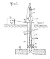
- FIG. 1 shows a well dug in an oil-producing zone 50 and comprising, in a casing 51, a production column 100. Between the lower end of the latter and the casing 51 is placed an annular sealing device or "packer" 53. A shutter tool 70 according to the invention is lowered slightly above the level of the producing area 50 using a cable 17 to which it is suspended. This cable, passing inside the production column 100, emerges at its top through a sealing device 72 to be wound, via deflection pulleys 73, 74, on the drum of a winch 75 arranged on the surface of the ground.
- the cable 17 is an electric cable which, in addition to a mechanical function of suspension and actuation of the tool 70, provides a function of transmission of measurement signals to the surface from devices which can be associated with the tool, such as a pressure gauge 15 intended to measure the pressure at the bottom of the well, below the tool.
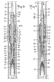
- the tool 70 shown in Figures 2A, 2B comprises a first tubular part 1, of great length.
- a second tubular part 2 which emerges upwards, and a third tubular part 3, below from which the part 1 contains a fourth tubular part 4.
- a fifth tubular part 5 is also provided, which crosses the whole along the longitudinal axis Z of the tool. All these parts can slide longitudinally with respect to each other.
- the head 1a of the part 1 contains stop pawls 11 and locking bolts 12 which can emerge therefrom at its periphery by corresponding orifices to engage in a groove 101 formed in a fitting with internal reach 100a which comprises column 100 at the level where the tool should be placed.
- Each stop pawl 11, provided with a spring 18 which tends to make it emerge from the head 1a of the part 1, is oriented so as to disappear when the tool descends into the column 100, the passage of possible obstacles on the internal wall thereof, but, during an upward movement of the tool, to engage in a cavity such as the groove 101 to stop the tool.
- the part 2 has, opposite each of them, a reduced radius in a zone 2a extending over a certain axial length, this radius increasing in a zone 2b situated below this zone, to which it is connected by a chamfer, to a value such that, if this zone 2b comes, by sliding of the part 2, opposite the corresponding pawl 11, it forces the latter to switch to the erased situation inside the head 1a of the part 1.
- the part 2 offers, opposite each locking bolt 12, a zone 2c, a zone 2d or a zone 2e, the zone 2d situated between zones 2c and 2e having a greater radius as the latter, as it forces the corresponding bolt 12 to emerge from the head 1a to engage in the groove 101, while when one of the zones 2c and 2e is opposite the bolt 12, the latter ci takes an erased position inside the head 1a.
- Zone 2d is connected to zones 2c and 2d by respective chamfers.
- the part 1 is extended upwards, beyond its head 1a, by a long elastic hook 1b which can come into engagement, depending on the mutual position of the parts 1 and 2, either in a peripheral groove 2f formed at the top of the piece 2, either in one of the two holes 2g, 2h drilled in the wall of piece 2, one below the other and both below the groove 2f.
- the part 1 has, below its head 1a, a first cylindrical zone 1c of diameter slightly smaller than that of the head 1a, then, below, connecting with the zone 1c by a conical chamfer, a second cylindrical zone 1d of diameter slightly smaller than that of zone 1c.
- Zone 1d is pierced with axially extending slots 1e, through which pass radial arms 3a which comprises the part 3 and which support a crown 3b surmounted by a pair of seals 13.
- the part 1 has a part 1f of larger diameter, substantially equal to that of the head 1a, then continues to its lower end by a long cylindrical sleeve 1g, with thin wall, of slightly smaller diameter.
- annular piston 4a belonging to the part 4 and projecting around a cylindrical sleeve 4b with thin wall, which can slide in the axial opening of an annular partition 1h that includes the piece 1 at the top of the socket 1 g.
- annular partition 1h that includes the piece 1 at the top of the socket 1 g.
- the part 4 widens into a conical head 4c forming a valve which cooperates with a conjugate seat 3c formed by the lower end of the part 3.
- the sleeve 4b is extends to end with a 4d part offering peripheral notches on its outer surface.
- the part 5 consists first of all of a head 5a of generally cylindrical shape, engaged in the upper part of the part 2 and capable of sliding in a sleeve 2i terminating this last part, with an internal diameter slightly smaller than the diameter of the rest of the part 2.
- a bulge 5b of conjugate diameter of the latter diameter, so that this bulge can slide in the part 2, but cannot pass through the sleeve 2i thereof, thus limiting an upward movement of the part 5 relative to the part 2.
- the bulge 5b carries a lug 25 engaged in a guide slot 2j formed in the part 2 in the axial direction, so that the parts 2 and 5 can execute a mutual sliding movement, but are integral in rotation about their common axis Z.
- groove 2f is hollowed out on the periphery of sleeve 2i, while the orifices 2g and 2h are drilled below the latter, in the cylindrical region of the part 2 where the bulge 5b can slide.
- the part 5 is continued, below its head 5a, by a long and thin rod 5c which crosses axially, inside the part 1, the bottom of the part 2, the part 3 and the part 4. If an annular gap is formed between the rod 5c and the internal cylindrical surface of the parts 2 and 3, said rod passes through the valve 4c that comprises the part 4 by an axial orifice of diameter conjugated to its own diameter. Below the valve 4c, the socket 4b of this same part remotely surrounds the rod 5c. Then this continues, after an annular shoulder 5d (FIG. 3), by a part 5e of slightly larger diameter which emerges downwards from the notched part 4d of the part 4.
- the part 5 offers a set of claws 5f oriented upwards in the axial direction and capable of coming into engagement with the notched part 4d of the part 4, the parts 4 and 5 then being coupled ( not definitively).
- a 5g collar At the foot of the claws 5f is a 5g collar; between this and the piston 4a is placed a compression spring 14 which tends to push the piston 4a upwards relative to the part 5.
- a pressure gauge 15 intended to measure the pressure of the fluid that the well contains. Its electrical connection wires pass right through the tool via an axial channel 5k which comprises the part 5 over its entire length and are connected to the electric cable 17 moored to the head 5a of this same part 5.
- the part 5 then has an externally threaded zone 5h, followed by a zone 5i of diameter greater than the average diameter of the threaded zone 5h.
- a part 6 is engaged around this part of the part 5. It comprises a sleeve 6a offering an internal thread combined with that of the zone 5h, on which it is screwed, and lugs 6b extending downward in the axial direction around the zone 5i and each ending in a boss 6c projecting radially outwards.
- the tabs 6b have their own elasticity which urges them towards the general axis Z of the tool.
- the free ends of the tabs 6b either rest on the part 5i, so that the bosses 6c are almost pushed back in contact with the internal surface of the socket 1 g of the part 1 and are then likely to come into abutment against a shoulder 1i projecting from said internal surface, or are located opposite part 5i of smaller diameter of part 5, so that the tabs 6b retract centripetally and their bosses 6c are erased and can therefore cross the shoulder 1i of the part 1.
- the sleeve 6a of the part 6 has at its periphery triangular bosses 61, 62, ..., arranged in staggered rows in two rows.
- the diameter of the sleeve 6a and the thickness of said bosses as well as of the abovementioned shoulder 1i are chosen so that the part 6 can move freely with respect to the latter, but that its bosses 61, 62, ..
- FIG. 8 where it has been assumed for convenience that it was the part 6 which was fixed and the part 1 with its pins 16 which moved, if, from an initial position 16 1 , the pin 16 shown moves in the downward axial direction, it meets in 16 2 the boss 62 which causes it to deflect to the right until 16 3 , then it continues its race in the axial direction to reach a position 16 4 , from which it then rises, meets in 16 5 the boss 63 which also causes it to deflect to the right until 16 6 , and reaches its final position 16, angularly distant from its initial position 16, by a fraction of a turn.
- the pin 16 is stationary and it is the part 6 which turns, to the left, of said fraction of a turn.
- this part can serve as an indexing member making it possible to count the number of back-and-forth movements carried out by the part 5 on which it is screwed.
- O-ring seals are provided in relation to the part 4: a seal 28 (Figure 4) between the valve 4c and the rod 5c; a seal 29 ( Figure 28) between the partition 1 h and the socket 4b; a seal 30 between the piston 4a and the bush 1g; a seal 31 ( Figure 3) between the lower part 4d of the part 4 and the corresponding 5th part of the part 5; finally, a seal 32 (FIG. 2B) on the valve 4c opposite its seat 3c.
- a seal 33 is also provided in the zone 1c of the part 1, which can cooperate either with the part 2 (FIG. 3), or with the part 3 (FIG. 4).
- the arrangement described shows two cylinder-piston assemblies: a first assembly comprising a cylinder formed by the bush 1g and the piston 4a of the part 4, integral with the valve 4c, and a second assembly comprising a cylinder formed by the bush 4b and a piston formed by part 5e of part 5, of diameter greater than that of part 5c which overcomes it and forms the actuating rod.
- the chamber 41 of variable volume of the first set limited by the socket 4b, the piston 4a, the socket 1g and the partition 1h, communicates through orifices 4e drilled in the socket 4b with the chamber 45 of variable volume of the second set, limited by the rod 5c, the shoulder 5d, the sleeve 4b and the valve 4c. These two chambers are filled with hydraulic fluid.
- the valve 4c Due to the presence of the hydraulic mechanism formed by the communicating chambers 41, 45, filled with hydraulic fluid, and their respective pistons 4a, 5e, the valve 4c which, in the closed position, after lowering the tool into the well, is subjected on the part of the pressurized fluid from the well to a force which tends to apply it against its seat 3c, receives from said hydraulic fluid, via the piston 4a, a force in the opposite direction which is deduced from the preceding one, so that the total force with which the valve 4c is pressed against its seat 3c in the closed position is reduced.
- the effective area of the piston of the chamber 45 is S l -S 2 .
- This mechanism also has an amplifying effect on the force f which must be applied to the part 5 via the cable 17 to obtain the opening of the valve 4c. Indeed, such a force f creates a pressure variation in chamber 45, which is reflected in chamber 41, so that the piston 4a applies an opening force to the valve 4c
- the tool having been lowered slightly below the fitting with internal reach 100a of the column 100, it is brought up until the pawls 11 come to engage in the groove 101 of said fitting, the part 1 there thereby finding it immobilized.
- An additional traction applied to the cable 17 brings up the part 5 which drives the part 2, the hook 1 escaping from the groove 2f to come to engage in the orifice 2g.
- This upward movement of the part 2 relative to the part causes on the one hand the engagement in the groove 101 of the bolts 12 by the raised area 2d of the part 2 and on the other hand the erasure of the pawls 11 by the zone 2b located below the zone 2a and of greater radial thickness than the latter.
- the ascent of the part 5 with respect to the part 1 also has the effect of bringing the part 6 back into the part 1, so that it escapes the pins 16 each of which was engaged in the locked position in one of the aforementioned notches 20 formed in the boss 61 and the diametrically opposite boss (FIG. 8).
- Each pin 16 then meets the boss 60 located below the boss 61 and is returned by it opposite the boss 61, so that at the subsequent loosening of the cable 17 causing a lowering of the part 6 ( Figure 4), the pin 16 meets the boss 61 which drives it towards the following bosses 62, 63, ..., without the pin 16 being able to return to the notch 20.
- the part 6 is definitively released and, when the cable is released above.
- the valve thus opening connects regions 1 and II of the production column via the annular gap between the latter and the sleeve 1g of the part 1, orifices 1j drilled in the wall of said part between the sleeve 1g and the part 1f which surmounts it, the annular gap which follows the seat 3c between the part 5c of the part 5 on the one hand and the internal surface of the parts 3 and 2 on the other hand, and orifices 2k drilled in the wall of the part 2.
- the part 5 has also raised the part 6, the sleeve 6a thereof crossing the level of the pins 16, so that the peripheral bosses of said sleeve have cooperated with said fixed pins which rotated the part 6 by a fraction of a turn on the threaded part 5h of the part 5, immobilized in rotation by the screw 25 engaged in the slot 2j of the part 2, this rotation of the part 6 causing it to rise slightly compared to room 5.
- valve 4c closes under the action of the spring 14 aided by the pressure P 1 of the fluid in the well, the part 6 rotating a new fraction of a turn.
- the number of opening / closing cycles of the tool valve is adjustable and depends on the initial position given to the indexing member 6 on the threaded part 5h of the part 5.
Description
La présente invention se rapporte à un outil d'obturation de la colonne de production d'un puits contenant un fluide sous pression, cet outil, conçu pour être temporairement fixé à l'intérieur de la colonne de production ou pour faire partie intégrante de celle-ci, comprenant une vanne qui peut être actionnée pour fermer ou ouvrir la colonne de production au passage du fluide du puits.The present invention relates to a tool for closing the production column of a well containing a pressurized fluid, this tool, designed to be temporarily fixed inside the production column or to be an integral part of it. -ci, comprising a valve which can be actuated to close or open the production column in the passage of the fluid from the well.
On sait que l'un des principaux essais permettant de déterminer la capacité de production d'un puits d'hydrocarbures consiste à arrêter la production à l'aide d'une vanne et à enregistrer les variations de pression résultant de la fermeture du puits. On sait par ailleurs qu'il est avantageux de pouvoir fermer la colonne de production à proximité immédiate de la zone souterraine productrice, de façon à éliminer certains effets perturbateurs dus à la compressibilité du fluide présent dans la colonne de production, qui se manifestent lorsqu'on effectue la fermeture en surface.It is known that one of the main tests for determining the production capacity of a hydrocarbon well consists in stopping production using a valve and recording the pressure variations resulting from the closing of the well. We also know that it is advantageous to be able to close the production column in the immediate vicinity of the producing underground zone, so as to eliminate certain disturbing effects due to the compressibility of the fluid present in the production column, which appear when the surface is closed.
Le brevet US-A-4 252 188 correspond au préambule de la revendication 1 et décrit un dispositif d'actionnement pour commander le fonctionnement d'une vanne d'admission installée dans un puits. Il comprend un premier piston annulaire qui est déplacé vers le haut sous l'action de la pression établie entre l'espace annulaire du puits et la colonne de production. Lors de ce déplacement le premier piston, en comprimant un ressort, fait descendre par l'intermédiaire d'une transmission hydraulique à double chambre un deuxième piston qui commande l'ouverture de la vanne.US-A-4 252 188 corresponds to the preamble of
L'invention a pour objet un outil d'obturation pouvant être installé dans la colonne de production d'un puits pendant la durée des essais effectués sur le puits, la vanne de cet outil étant d'une manoeuvre aisée malgré la pression considérable qui peut régner dans le puits et qui s'oppose à l'ouverture de la vanne après qu'elle ait été fermée.The subject of the invention is a sealing tool which can be installed in the production column of a well for the duration of the tests carried out on the well, the valve of this tool being easy to maneuver despite the considerable pressure which can reign in the well and which opposes the opening of the valve after it has been closed.
Dans ce but, l'outil selon l'invention comprend des chambres respectives de volume variable, de section différente, communiquant entre elles et remplies d'un liquide hydraulique qui s'y trouve de préférence confiné; le piston du premier ensemble agit sur la vanne dans le sens de son ouverture sous l'effet de la pression du liquide hydraulique à laquelle il est soumis, ce piston offrant une face intérieure, en contact avec le liquide hydraulique, dont la surface est supérieure à la surface de la face intérieure du piston du second ensemble. Le piston du second ensemble coulisse dans le cylindre correspondant suivant la direction de l'axe longitudinal de l'outil et sa disposition est telle que, lorsqu'il est sollicité vers le haut par un câble qui lui est attaché, il cause une diminution du volume de la chambre dudit ensemble. Par suite, en appliquant une force de traction au câble qui remonte jusqu'à la surface à l'intérieur de la colonne de production, on obtient un effet multiplicateur sur cette force qui permet de commander l'ouverture de la vanne malgré la pression des fluides du puits qui s'oppose à cette ouverture.For this purpose, the tool according to the invention comprises respective chambers of variable volume, of different section, communicating with one another and filled with a hydraulic liquid which is preferably confined therein; the piston of the first assembly acts on the valve in the direction of its opening under the effect of the pressure of the hydraulic fluid to which it is subjected, this piston offering an inner face, in contact with the hydraulic fluid, the surface of which is greater on the surface of the inner face of the piston of the second set. The piston of the second set slides in the corresponding cylinder in the direction of the longitudinal axis of the tool and its arrangement is such that, when it is stressed upwards by a cable which is attached to it, it causes a reduction in the volume of the chamber of said assembly. Consequently, by applying a tensile force to the cable which goes up to the surface inside the production column, a multiplier effect is obtained on this force which makes it possible to control the opening of the valve despite the pressure of the well fluids that oppose this opening.
De plus, il convient que le piston du second ensemble offre une surface extérieure qui est soumise à la pression du puits en amont de la vanne et qui est supérieure à la surface de la face intérieure dudit piston. Grâce à cette disposition, la vanne en situation de fermeture reçoit du piston du premier ensemble, soumis à la pression du liquide hydraulique qui est supérieure à la pression ambiante régnant dans le puits où se trouve l'outil, une force dans le sens de son ouverture, qui vient en déduction de la force que la vanne reçoit directement du fluide sous pression du puits, qui tend à la maintenir fermée. Ainsi, la vanne est soulagée et son ouverture est obtenue moyennant l'application d'une force de commande réduite par rapport à la force qui serait nécessaire en l'absence dudit mécanisme hydraulique, toute mesure d'égalisation de pression de part et d'autre du clapet préalablement à son ouverture devenant superflue. Cet effet se conjugue avec l'effet multiplicateur de force précité et conduit à une nouvelle diminution de la force à appliquer pour obtenir l'ouverture de la vanne.In addition, the piston of the second set should offer an external surface which is subjected to the pressure of the well upstream of the valve and which is greater than the surface of the internal face of said piston. Thanks to this arrangement, the valve in closed position receives from the piston of the first assembly, subjected to the pressure of the hydraulic fluid which is higher than the ambient pressure prevailing in the well where the tool is located, a force in the direction of its opening, which is deducted from the force that the valve receives directly from the pressurized fluid from the well, which tends to keep it closed. Thus, the valve is relieved and its opening is obtained by applying a reduced control force compared to the force which would be necessary in the absence of said hydraulic mechanism, any measure of pressure equalization on the part and other of the valve prior to its opening becoming superfluous. This effect is combined with the aforementioned force multiplier effect and leads to a further reduction in the force to be applied to obtain the opening of the valve.
En pratique, la vanne se composera normalement d'un clapet et d'un siège conjugué, ce clapet étant solidaire du piston du premier ensemble.In practice, the valve will normally consist of a valve and a conjugate seat, this valve being integral with the piston of the first assembly.
Dans une force d'exécution préférée, on donne à la structure du mécanisme hydraulique une configuration coaxiale. Plus précisément, on peut prévoir que le clapet de la vanne soit solidaire d'une douille cylindrique dont l'axe est parallèle à la direction de déplacement du clapet et qui porte extérieurement le piston du premier ensemble sous la forme d'un piston annulaire coulissant dans une douille cylindrique fixe, formant la paroi latérale du cylindre du premier ensemble et fermée par une cloison transversale qui est située entre le clapet et le piston et à travers laquelle peut coulisser de façon étanche la douille solidaire du clapet, cette dernière douille formant la paroi latérale de la chambre du second ensemble, laquelle communique avec la chambre du premier ensemble par au moins un orifice percé dans ladite paroi, et dans laquelle coulisse le piston du second ensemble, ce piston étant solidaire d'une tige d'actionnement qui peut coulisser de façon étanche à travers le clapet et à laquelle est attaché un câble tel que le câble précité, susceptible de commander, lorsqu'un effort de traction lui est appliqué, l'ouverture de la vanne par déplacement du clapet via ledit mécanisme hydraulique.In a preferred execution force, the structure of the hydraulic mechanism is given a coaxial configuration. More specifically, it can be provided that the valve flap is integral with a cylindrical sleeve whose axis is parallel to the direction of movement of the valve and which externally carries the piston of the first assembly in the form of a sliding annular piston in a fixed cylindrical sleeve, forming the side wall of the cylinder of the first set and closed by a transverse partition which is situated between the valve and the piston and through which the sleeve integral with the valve can slide in leaktight manner, the latter sleeve forming the side wall of the chamber of the second assembly, which communicates with the chamber of the first assembly by at least one orifice drilled in said wall, and in which the piston of the second assembly slides, this piston being integral with an actuating rod which can slide tightly through the valve and to which is attached a cable such as the aforementioned cable, capable of controlling, lo rs a tensile force is applied to it, the opening of the valve by displacement of the valve via said hydraulic mechanism.
Lorsqu'il s'agit d'un outil amovible fixé temporairement dans une colonne de production, on peut prévoir, pour permettre le verrouillage de l'outil au niveau désiré, que la douille formant la paroi latérale du cylindre du premier ensemble se prolonge au delà de la cloison qui limite la chambre de cet ensemble par une partie de forme générale tubulaire, comportant au moins un cliquet et au moins un pêne de verrouillage pouvant s'escamoter dans ladite partie tubulaire ou en faire radialement saillie pour s'engager dans une gorge périphérique que comporte un raccord à portée intérieure placé dans la colonne de production à l'endroit où l'outil doit être mis en station, les mouvements radiaux dudit cliquet et dudit pêne étant commandés par une pièce tubulaire mobile dans la direction de l'axe longitudinal de l'outil, disposée coaxialement à l'intérieur de ladite partie tubulaire et comportant des zones de rayons différents sur lesquelles prennent appui ledit cliquet et ledit pêne, la position de ces derniers étant tributaire de la zone respective de la pièce tubulaire qui se trouve en regard.In the case of a removable tool temporarily fixed in a production column, it can be provided, in order to allow the tool to be locked at the desired level, that the sleeve forming the side wall of the cylinder of the first set extends to the beyond the partition which limits the chamber of this assembly by a part of generally tubular shape, comprising at least one pawl and at least one locking bolt which can be retracted in said tubular part or radially protrude therefrom to engage in a peripheral groove that includes a fitting with internal reach placed in the production column at the place where the tool is to be stationed, the radial movements of said pawl and of said bolt being controlled by a movable tubular part in the direction of the longitudinal axis of the tool, arranged coaxially inside said tubular part and comprising zones of different radii on which said pawl and said bolt bear, the position of the latter being dependent on the respective zone of the tubular part which is opposite.
De préférence, ladite pièce tubulaire peut prendre trois positions déterminées par rapport à ladite partie tubulaire, savoir une première position où le cliquet peut émerger en saillie, sous l'action d'un ressort, et le pêne est rétracté en situation escamotée, une seconde position où le cliquet est rétracté et le pêne émerge et une troisième position où le cliquet et le pêne sont rétractés, les passages de la pièce tubulaire de sa première à sa seconde, puis à sa troisième position étant commandés par des déplacements longitudinaux de la tige du piston du second ensemble sous l'effet de tractions successives appliquées au câble attaché à cette tige. Dans la première position de ladite pièce, le cliquet commande l'arrêt de l'outil dans le raccord à portée intérieure; dans la seconde position, le pêne y assure le verrouillage de l'outil; dans la troisième position, l'outil est déverrouillé et peut être remonté.Preferably, said tubular part can take three determined positions with respect to said tubular part, namely a first position where the pawl can emerge projecting, under the action of a spring, and the bolt is retracted in retracted position, a second position where the pawl is retracted and the bolt emerges and a third position where the pawl and the bolt are retracted, the passages of the tubular part from its first to its second, then to its third position being controlled by longitudinal displacements of the rod of the piston of the second set under the effect of successive pulls applied to the cable attached to this rod. In the first position of said part, the pawl controls the stopping of the tool in the fitting with internal reach; in the second position, the bolt locks the tool there; in the third position, the tool is unlocked and can be reassembled.
Pour obtenir le passage de l'une à l'autre de ces positions de la pièce tubulaire, on peut prévoir que, la pièce tubulaire étant initialement dans sa première position, le clapet repousse, à sa première fermeture commandée par la tige dudit piston, ladite pièce pour l'amener dans sa seconde position. On peut prévoir en outre, pour réaliser le déverrouillage de l'outil à la fin d'un nombre prédéterminé de cycles d'ouverture/ fermeture de la vanne, que cette même tige de piston soit couplée à un organe d'indexage qui avance d'un pas à chaque déplacement en va-et-vient de la tige correspondant à un cycle d'ouverture-fermeture de la vanne, et que cet organe limite la course de la tige dans le sens correspondant à l'ouverture du clapet jusqu'à ce qu'il ait accompli un nombre de pas déterminé, après quoi il s'efface pour laisser se prolonger la course de la tige, celle-ci commandant alors le passage de la pièce tubulaire de sa seconde à sa troisième position, donc la libération de l'outil pour sa remontée.To obtain the passage from one to the other of these positions of the tubular part, it can be provided that, the tubular part being initially in its first position, the valve pushes back, on its first closure controlled by the rod of said piston, said part to bring it into its second position. Provision may also be made, in order to unlock the tool at the end of a predetermined number of valve opening / closing cycles, for this same piston rod to be coupled to an indexing member which advances d '' one step at each back-and-forth movement of the rod corresponding to an opening-closing cycle of the valve, and that this member limits the stroke of the rod in the direction corresponding to the opening of the valve until that he has completed a determined number of steps, after which he disappears to allow the stroke of the rod to continue, the latter then controlling the passage of the tubular part from its second to its third position, therefore the release of the tool for its ascent.
Afin d'imposer au clapet de demeurer ouvert durant cette phase finale de remontée de l'outil, on peut doter ladite tige et la douille solidaire du clapet d'organes d'accrochage grâce auxquels elles se verrouillent mutuellement lorsque la tige accomplit sa course prolongée qui cause le déverrouillage de l'outil, le clapet se trouvant dès lors maintenu en situation d'ouverture.In order to force the valve to remain open during this final phase of raising the tool, it is possible to provide said rod and the sleeve integral with the valve with hooking members by means of which they lock each other when the rod completes its extended stroke. which causes the unlocking of the tool, the valve being therefore maintained in the open situation.
D'autres caractéristiques et avantages de l'invention ressortiront plus clairement de la description qui va suivre, en regard des dessins annexés, d'un exemple de réalisation non limitatif.
- La figure 1 représente schématiquement, en coupe verticale, un puits dans lequel a été mis en place un outil d'obturation selon l'invention.
- Les figures 2A et 2B représentent, en coupe longitudinale partielle, un outil selon l'invention, respectivement par moitiés, les deux figures se raccordant suivant la ligne AA'.
- Les figures 3 à 6 représentent, à plus petite échelle, l'outil des figures 2A, 2B dans différentes phases d'utilisation.
- La figure 7 est une vue en section schématique de la partie de l'outil où se trouve le mécanisme hydraulique d'actionnement de la vanne d'obturation qu'il comporte.
- La figure 8 illustre schématiquement le fonctionnement de l'organe d'indexage de l'outil destiné à limiter le nombre de cycles d'ouverture/fermeture de la vanne.
- FIG. 1 schematically represents, in vertical section, a well in which a sealing tool according to the invention has been put in place.
- FIGS. 2A and 2B show, in partial longitudinal section, a tool according to the invention, respectively in halves, the two figures connecting along line AA '.
- Figures 3 to 6 show, on a smaller scale, the tool of Figures 2A, 2B in different phases of use.
- Figure 7 is a schematic sectional view of the part of the tool where the hydraulic mechanism for actuating the shut-off valve is located.
- FIG. 8 schematically illustrates the operation of the indexing member of the tool intended to limit the number of opening / closing cycles of the valve.
On voit sur la figure 1 un puits creusé dans une zone 50 productrice de pétrole et comportant, dans un tubage 51, une colonne de production 100. Entre l'extrémité inférieure de cette dernière et le tubage 51 est placé un dispositif d'étanchéité annulaire ou "packer" 53. Un outil d'obturation 70 selon l'invention est descendu peu au-dessus du niveau de la zone productrice 50 à l'aide d'un câble 17 auquel il est suspendu. Ce câble, passant à l'intérieur de la colonne de production 100, en émerge à son sommet à travers un dispositif d'étanchéité 72 pour aller s'enrouler, via des poulies de renvoi 73, 74, sur le tambour d'un treuil 75 disposé à la surface du sol. Le câble 17 est un câble électrique qui, outre une fonction mécanique de suspension et d'actionnement de l'outil 70, assure une fonction de transmission de signaux de mesure vers la surface à partir de dispositifs qui peuvent être associés à l'outil, tels qu'un manomètre 15 destiné à mesurer la pression au fond du puits, au-dessous de l'outil.FIG. 1 shows a well dug in an oil-producing
Dans la description qui suit de l'outil d'obturation 70, on a supposé que celui-ci se trouvait en position normale d'utilisation dans un puits vertical.In the following description of the
L'outil 70 représenté aux figures 2A, 2B comprend une première pièce tubulaire 1, de grande longueur. Dans la tête 1 a de cette pièce, élargie au diamètre interne de la colonne de production 100 où est descendu l'outil, sont engagées une seconde pièce tubulaire 2, qui émerge vers le haut, et une troisième pièce tubulaire 3, au-dessous de laquelle la pièce 1 contient une quatrième pièce tubulaire 4. Une cinquième pièce tubulaire 5 est en outre prévue, qui traverse le tout suivant l'axe longitudinal Z de l'outil. Toutes ces pièces peuvent coulisser longitudinalement les unes par rapport aux autres.The
La tête 1 a de la pièce 1 contient des cliquets d'arrêt 11 et des pênes de verrouillage 12 qui peuvent en émerger à sa périphérie par des orifices correspondants pour s'engager dans une gorge 101 pratiquée dans un raccord à portée intérieure 100a que comporte la colonne 100 au niveau où doit se placer l'outil. Chaque cliquet d'arrêt 11, muni d'un ressort 18 qui tend à le faire émerger de la tête 1a de la pièce 1, est orienté de façon à s'effacer, lors de la descente de l'outil dans la colonne 100, au passage d'obstacles éventuels sur la paroi interne de celle-ci, mais, lors d'un mouvement ascendant de l'outil, à s'engager dans une cavité telle que la gorge 101 pour arrêter l'outil. Afin de ne pas gêner les mouvements de basculement des cliquets 11, la pièce 2 présente, en regard de chacun d'eux, un rayon réduit dans une zone 2a s'étendant sur une certaine longueur axiale, ce rayon augmentant dans une zone 2b située au-dessous de cette zone, à laquelle elle se raccorde par un chanfrein, à une valeur telle que, si cette zone 2b vient, par coulissement de la pièce 2, en regard du cliquet 11 correspondant, elle oblige ce dernier à basculer en situation effacée à l'intérieur de la tête 1a de la pièce 1.The head 1a of the
Suivant sa position par rapport à la pièce 1, la pièce 2 offre, en regard de chaque pêne de verrouillage 12, une zone 2c, une zone 2d ou une zone 2e, la zone 2d située entre les zones 2c et 2e présentant un plus grand rayon que ces dernières, tel qu'il oblige le pêne 12 correspondant à émerger de la tête 1a pour s'engager dans la gorge 101, tandis que lorsque l'une des zones 2c et 2e se trouve en regard du pêne 12, celui-ci prend une position effacée à l'intérieur de la tête 1a. La zone 2d se raccorde aux zones 2c et 2d par des chanfreins respectifs.Depending on its position relative to the
La pièce 1 se prolonge vers le haut, au delà de sa tête 1a, par un long crochet élastique 1 b qui peut venir en prise, suivant la position mutuelle des pièces 1 et 2, soit dans une gorge périphérique 2f pratiquée au sommet de la pièce 2, soit dans l'un des deux trous 2g, 2h percés dans la paroi de la pièce 2, l'un au-dessous de l'autre et tous deux au-dessous de la gorge 2f.The
La pièce 1 présente, au-dessous de sa tête 1a, une première zone cylindrique 1c de diamètre légèrement inférieur à celui de la tête 1a, puis, au-dessous, se raccordant avec la zone 1c par un chanfrein conique, une seconde zone cylindrique 1d de diamètre légèrement inférieur à celui de la zone 1c. La zone 1d est percée de fentes 1e s'étendant axialement, à travers lesquelles passent des bras radiaux 3a que comporte la pièce 3 et qui supportent une couronne 3b surmontée d'une paire de joints d'étanchéité 13. Au-dessous de la zone 1d, la pièce 1 présente une partie 1f de diamètre plus grand, sensiblement égal à celui de la tête 1a, puis se continue jusqu'à son extrémité inférieure par une longue douille cylindrique 1g, à paroi mince, de diamètre un peu plus petit. A l'intérieur de cette douille peut coulisser suivant la direction axiale un piston annulaire 4a appartenant à la pièce 4 et faisant saillie autour d'une douille cylindrique 4b à paroi mince, qui peut coulisser dans l'ouverture axiale d'une cloison annulaire 1h que comporte la pièce 1 au sommet de la douille 1 g. Au-dessus de cette cloison, la pièce 4 s'élargit en une tête conique 4c formant un clapet qui coopère avec un siège conjugué 3c formé par l'extrémité inférieure de la pièce 3. Au-dessous du piston 4a, la douille 4b se prolonge pour se terminer par une partie 4d offrant sur sa surface extérieure des crans périphériques.The
La pièce 5 se compose tout d'abord d'une tête 5a de forme générale cylindrique, engagée dans la partie supérieure de la pièce 2 et pouvant coulisser dans un manchon 2i terminant cette dernière pièce, de diamètre interne légèrement inférieur au diamètre du reste de la pièce 2. A la base de la tête 5a se trouve un renflement 5b de diamètre conjugué de ce dernier diamètre, de sorte que ce renflement peut coulisser dans la pièce 2, mais ne peut franchir le manchon 2i de celle-ci, limitant ainsi un mouvement vers le haut de la pièce 5 par rapport à la pièce 2. D'autre part, le renflement 5b porte un ergot 25 engagé dans une fente de guidage 2j pratiquée dans la pièce 2 suivant la direction axiale, de sorte que les pièces 2 et 5 peuvent exécuter un mouvement de coulissement mutuel, mais sont solidaires en rotation autour de leur axe commun Z.The
On notera que la gorge 2f précitée est creusée sur le pourtour de manchon 2i, tandis que les orifices 2g et 2h sont percés au-dessous de celui-ci, dans la région cylindrique de la pièce 2 où peut coulisser le renflement 5b.It will be noted that the
La pièce 5 se poursuit, au-dessous de sa tête 5a, par une tige 5c longue et mince, qui traverse axialement, à l'intérieur de la pièce 1, le bas de la pièce 2, la pièce 3 et la pièce 4. Si un intervalle annulaire est ménagé entre la tige 5c et la surface cylindrique interne des pièces 2 et 3, ladite tige traverse le clapet 4c que comporte la pièce 4 par un orifice axial de diamètre conjugué à son propre diamètre. Au-dessous du clapet 4c, la douille 4b de cette même pièce entoure à distance la tige 5c. Puis celle-ci se poursuit, après un épaulement annulaire 5d (figure 3), par une partie 5e de diamètre un peu supérieur qui émerge vers le bas de la partie crantée 4d de la pièce 4.The
Au bas de cette partie 5e, la pièce 5 offre un jeu de griffes 5f orientées vers le haut dans la direction axiale et susceptibles de venir en prise avec la partie crantée 4d de la pièce 4, les pièces 4 et 5 se trouvant alors accouplées (de façon non définitive). Au pied des griffes 5f se trouve un collet 5g; entre celui-ci et le piston 4a est placé un ressort de compression 14 qui tend à repousser le piston 4a vers le haut par rapport à la pièce 5.At the bottom of this
A l'extrémité inférieure de la pièce 5 est fixé un manomètre 15 destiné à mesurer la pression du fluide que contient le puits. Ses fils de connexion électrique traversent l'outil de part en part via un canal axial 5k que comporte la pièce 5 sur toute sa longueur et sont connectés au câble électrique 17 amarré à la tête 5a de cette même pièce 5.At the lower end of the
La pièce 5 présente ensuite une zone 5h filetée extérieurement, suivie d'une zone 5i de diamètre supérieur au diamètre moyen de la zone filetée 5h. Une pièce 6 est engagée autour de cette partie de la pièce 5. Elle comprend un manchon 6a offrant un filetage interne conjugué de celui de la zone 5h, sur laquelle il est vissé, et des pattes 6b s'étendant vers le bas en direction axiale autour de la zone 5i et se terminant chacune par un bossage 6c faisant radialement saillie vers l'extérieur. Les pattes 6b sont dotées d'une élasticité propre qui les sollicite vers l'axe général Z de l'outil. Suivant la position relative de la pièce 6 sur la pièce 5 (qui dépend de son degré de vissage sur la partie filetée 5h), les extrémités libres des pattes 6b soit trouvent appui sur la partie 5i, de sorte que les bossages 6c sont repoussés quasiment en contact avec la surface interne de la douille 1 g de la pièce 1 et sont alors susceptibles de venir en butée contre un épaulement 1i en saillie sur ladite surface interne, soit se trouvent en regard de la partie 5i de moindre diamètre de la pièce 5, de sorte que les pattes 6b se rétractent de façon centripète et que leurs bossages 6c s'effacent et peuvent dès lors franchir l'épaulement 1i de la pièce 1.The
Le manchon 6a de la pièce 6 présente à sa périphérie des bossages triangulaires 61, 62,..., disposés en quinconce sur deux rangées. Le diamètre du manchon 6a et l'épaisseur desdits bossages ainsi que de l'épaulement 1i précité sont choisis de façon que la pièce 6 puisse se déplacer librement vis-à-vis de ce dernier, mais que ses bossages 61, 62,..., coopèrent avec une paire de pions 16 faisant saillie à l'intérieur de la douille 1g de la pièce 1 en situation diamétralement opposée, ceci afin de faire tourner d'une fraction de tour la pièce 6 par rapport à la pièce 1 et, solidaires de cette dernière en rotation, les pièces 2 et 5, à chaque fois que les deux rangées de bossages 61, 62, ..., passent devant les pions 16.The
Considérant la figure 8 où on a supposé par commodité que c'était la pièce 6 qui était fixe et la pièce 1 avec ses pions 16 qui se déplaçait, si, à partir d'une position initiale 161, le pion 16 représenté se déplace en direction axiale vers le bas, il recontre en 162 le bossage 62 qui le fait dévier vers la droite jusqu'en 163, puis il poursuit sa course en direction axiale pour atteindre une position 164, d'où il remonte ensuite, recontre en 165 le bossage 63 qui le fait également dévier vers la droite jusqu'en 166, et atteint sa position finale 16, distante angulairement de sa position initiale 16, d'une fraction de tour. En réalité, le pion 16 est immobile et c'est la pièce 6 qui tourne, vers la gauche, de ladite fraction de tour. Ainsi, cette pièce peut servir d'organe d'indexage permettant de compter le nombre de déplacements en va-et-vient exécutés par la pièce 5 sur laquelle elle est vissée.Considering FIG. 8 where it has been assumed for convenience that it was the
Des joints toriques d'étanchéité sont prévus en relation avec la pièce 4: un joint 28 (figure 4) entre le clapet 4c et la tige 5c; un joint 29 (figure 28) entre la cloison 1 h et la douille 4b; un joint 30 entre le piston 4a et la douille 1g; un joint 31 (figure 3) entre la partie inférieure 4d de la pièce 4 et la partie 5e correspondante de la pièce 5; enfin, un joint 32 (figure 2B) sur le clapet 4c en regard de son siège 3c. Un joint 33 est également prévu dans la zone 1c de la pièce 1, qui peut coopérer soit avec la pièce 2 (figure 3), soit avec la pièce 3 (figure 4).O-ring seals are provided in relation to the part 4: a seal 28 (Figure 4) between the
La disposition décrite fait apparaître deux ensembles cylindre-piston: un premier ensemble comprenant un cylindre formé par la douille 1g et le piston 4a de la pièce 4, solidaire du clapet 4c, et un second ensemble comprenant un cylindre formé par la douille 4b et un piston formé par la partie 5e de la pièce 5, de diamètre supérieur à celui de la partie 5c qui le surmonte et en forme la tige d'actionnement. La chambre 41 de volume variable du premier ensemble, limitée par la douille 4b, le piston 4a, la douille 1g et la cloison 1h, communique par des orifices 4e percés dans la douille 4b avec la chambre 45 de volume variable du second ensemble, limitée par la tige 5c, l'épaulement 5d, la douille 4b et le clapet 4c. Ces deux chambres sont remplies de liquide hydraulique.The arrangement described shows two cylinder-piston assemblies: a first assembly comprising a cylinder formed by the
Du fait de la présence du mécanisme hydraulique formé par les chambres communiquantes 41, 45, remplies de fluide hydraulique, et leurs pistons respectifs 4a, 5e, le clapet 4c qui, en position de fermeture, après descente de l'outil dans le puits, est soumis de la part du fluide sous pression du puits à une force qui tend à l'appliquer contre son siège 3c, reçoit dudit fluide hydraulique, par l'intermédiaire du piston 4a, une force en sens contraire qui se déduit de la précédente, de sorte que la force totale avec laquelle le clapet 4c est pressé contre son siège 3c en position de fermeture est réduite.Due to the presence of the hydraulic mechanism formed by the communicating
En effet (cf. figure 7), si l'on appelle respectivement Si et S2 les sections des parties 5e et 5c de la pièce 5,Indeed (cf. FIG. 7), if we respectively call Si and S 2 the sections of
la surface effective du piston de la chambre 45 est Sl-S2. La pièce 5 reçoit d'une part, du fluide du puits où règne une pression Pi, une force F1=P1S1 the effective area of the piston of the
dirigée vers le haut, et d'autre part, du fluide de la chambre 45 où règne une pression P2, une force F2=P2S2 directed upwards, and on the other hand, of the fluid of the
dirigée vers le bas. La pièce 5 étant en équilibre entre le milieu du puits à la pression P1 et le milieu au-dessus du clapet 4c dont la pression est négligeable, on a![]()
![]()
![]()
![]()
Etant donné que Si est supérieur à S2, la pression P2 dans la double chambre 41, 45 est supérieure à la pression P, régnant dans le puits.Since Si is greater than S 2 , the pressure P 2 in the
Si maintenant on appelle respectivement S3, S4 et S5 les surfaces qu'offrent au milieu à la pression P, le clapet 3c, la partie 5e de la pièce 5 et le piston 4a, ce dernier offrant au fluide de la chambre 41 une surface Se, on constate que le clapet 4c est soumis
- à une force Fh vers le haut de la part de la pression P,:

- et à une force Fb vers le bas de la part de la pression P2:

- at a force F h upwards from the pressure P ,:
- and to a downward force F b from the pressure P 2 :
En supposant pour simplifier que![]()
![]()
![]()
![]()
![]()
![]()
![]()
![]()
Si les valeurs de Si et S2 sont par exemple choisies respectivement égales à 2 cm2 et 1,5 cm2, on voit que la force Fb créée vers le bas par le fluide hydraulique de la chambre 41 est égale aux deux tiers de la force Fh exercée vers le haut par le fluide du puits, la force résultante Fh-Fb à laquelle est soumis le clapet 4c étant ainsi abaissée au tiers de la force Fh qu'il subirait dans le sens de la fermeture en l'absence du mécanisme hydraulique à deux pistons.If the values of Si and S 2 are for example chosen respectively equal to 2 cm 2 and 1.5 cm 2 , it can be seen that the force F b created downwards by the hydraulic fluid of the
Ce mécanisme a par ailleurs un effet amplificateur sur la force f qui doit être appliquée à la pièce 5 via le câble 17 pour obtenir l'ouverture du clapet 4c. En effet, une telle force f crée une variation de pression![]()
![]()
![]()
![]()
Avec les valeurs indiquées précédemment à titre d'exemple pour S, et S2 et en choisissant pour S6 la valeur de 15 cm2, on voit que le coefficient amplificateur de force S6/(S1-S2) s'élève à 30. Par suite, grâce au mécanisme hydraulique d'actionnement du clapet 4c, il suffit dans le cas pratique considéré d'appliquer au câble 17 une force de traction f de valeur 30x3=90 fois plus petite que la force qu'il faudrait appliquer directement au clapet en l'absence dudit mécanisme hydraulique.With the values indicated above by way of example for S, and S 2 and by choosing for S 6 the value of 15 cm 2 , we see that the force amplifying coefficient S 6 / (S 1 -S 2 ) rises to 30. As a result, thanks to the hydraulic mechanism for actuating the
Le fonctionnement de l'outil au cours de son utilisation va maintenant être décrit.The operation of the tool during its use will now be described.
Lorsque l'outil est descendu dans la colonne de production 100 du puits, ses différents éléments sont dans la situation illustrée à la figure 3. Le crochet élastique 1 b de la pièce 1 est en prise avec la gorge 2f de la pièce 2, de sorte que les pênes 12 se trouvent en regard de la zone en retrait 2c de la pièce 2 et sont donc en position escamotée à l'intérieur de celle-ci. Durant la descente de l'outil, les cliquets 11 frottent contre la surface interne de la colonne de production en s'effaçant élastiquement; par contre, les joints d'étanchéité 13 reposent dans la zone en retrait 1d de la pièce 1, de sorte que tout contact avec la surface interne de la colonne 100 leur est épargné. La pièce 6 est verrouillée dans la pièce 1, les deux pions 16 de cette dernière se trouvant logés dans des encoches 20 correspondantes de la pièce 6 (figure 8), dans laquelle se trouve vissée en situation haute la pièce 5, son collet 5g étant espacé de l'extrémité supérieure de la pièce 6. Les pièces 1, 5 et 6 sont donc mutuellement immobilisées, le clapet 4c se trouvant en position d'ouverture à distance de son siège 3c, tandis que le ressort 14 est comprimé entre le collet 5g et le piston 4a.When the tool is lowered into the
L'outil ayant été descendu légèrement au-dessous du raccord à portée intérieure 100a de la colonne 100, on le fait remonter jusqu'à ce que les cliquets 11 viennent s'engager dans la gorge 101 dudit raccord, la pièce 1 s'y trouvant de ce fait immobilisée. Un surcroît de traction appliqué au câble 17 fait remonter la pièce 5 qui entraîne la pièce 2, le crochet 1 échappant à la gorge 2f pour venir s'engager dans l'orifice 2g. Ce déplacement vers le haut de la pièce 2 par rapport à la pièce cause d'une part la mise en prise dans la gorge 101 des pênes 12 par la zone en relief 2d de la pièce 2 et d'autre part l'effacement des cliquets 11 par la zone 2b située au-dessous de la zone 2a et de plus grande épaisseur radiale que celle-ci. La remontée de la pièce 5 par rapport à la pièce 1 a également pour effet de faire remonter la pièce 6 dans la pièce 1, de sorte qu'elle échappe aux pions 16 dont chacun se trouvait engagé en position de verrouillage dans l'une des encoches 20 précitées pratiquées dans le bossage 61 et le bossage diamétralement opposé (figure 8). Chaque pion 16 rencontre alors le bossage 60 situé au-dessous du bossage 61 et se trouve renvoyé par lui en regard du bossage 61, de sorte qu'au relâchement ultérieur du câble 17 causant un abaissement de la pièce 6 (figure 4), le pion 16 rencontre le bossage 61 qui le chasse vers les bossages suivants 62, 63, ..., sans que le pion 16 puisse revenir dans l'encoche 20. Ainsi la pièce 6 se trouve définitivement libérée et, lors du relâchement précité du câble 17, elle laisse descendre la pièce 5 dans la pièce 1. Ce mouvement autorise une diminution du volume de la chambre hydraulique 41 en correspondance avec l'augmentation de celui de la chambre 45, donc, sous l'action du ressort 14, une remontée de la pièce 4 et du clapet 4c que celle-ci comporte. Ledit clapet rencontre son siège 3c et repousse vers le haut la pièce 3 à laquelle celui-ci appartient, ainsi que la couronne 3b qui force les joints toriques 13 à quitter la zone 1d de petit diamètre pour gagner la zone 1cde plus grand diamètre où ils se trouvent comprimés contre la surface interne de la colonne 100 et assurent par suite l'étanchéité entre les régions et Il de la colonne 100 situées respectivement au-dessus et au-dessous d'eux (cf. le brevet français 2586781). Finalement, le clapet 4c se trouve appliqué en situation d'obturation sur son siège 3c, la pièce 3 étant en butée contre la pièce 2. Les deux régions 1 et Il précitées de la colonne 100 sont donc isolées l'une de l'autre.The tool having been lowered slightly below the fitting with
Lorsqu'on désire mettre en communication lesdites parties et Il par ouverture de la vanne formée par le clapet 4c et son siège 3b, on exerce une traction sur le câble 17 (figure 5). La pièce 5 remonte (jusqu'à venue en butée des bossages 6c de la pièce 6 sur l'épaulement 1i de la pièce 1) et le piston 5e qu'elle comporte fait diminuer le volume de la chambre hydraulique 45, ce qui cause une augmentation de celui de la chambre hydraulique 41 et par suite en abaissement de la pièce 4 et du clapet 4c avec une force multipliée. La valve s'ouvrant ainsi met en communication les régions 1 et Il de la colonne de production via l'intervalle annulaire entre cette dernière et le manchon 1g de la pièce 1, des orifices 1j percés dans la paroi de ladite pièce entre la douille 1g et la partie 1f qui la surmonte, l'intervalle annulaire qui fait suite au siège 3c entre la partie 5c de la pièce 5 d'une part et la surface interne des pièces 3 et 2 d'autre part, et des orifices 2k percés dans la paroi de la pièce 2. Corrélativement, la pièce 5 a fait remonter aussi le pièce 6, le manchon 6a de celle-ci franchissant le niveau des pions 16, de sorte que les bossages périphériques dudit manchon ont coopéré avec lesdits pions fixes, ce qui a fait tourner la pièce 6 d'une fraction de tour sur la partie filetée 5h de la pièce 5, immobilisée en rotation par la vis 25 engagée dans la fente 2j de la pièce 2, cette rotation de la pièce 6 la faisant légèrement remonter par rapport à la pièce 5.When it is desired to put said parts and II in communication by opening the valve formed by the
Lorsqu'on relâche le câble 17, le clapet 4c se referme sous l'action du ressort 14 aidé par la pression P1 du fluide du puits, la pièce 6 tournant d'une nouvelle fraction de tour.When the
Ainsi, par traction et relâchement successifs du câble 17, on obtient respectivement l'ouverture et la fermeture de la vanne 4c, 3c, l'ouverture de celle-ci ne demandant qu'une force de traction relativement faible grâce aux effets de soulagement du clapet et d'amplification de la force utile appliquée à celui-ci que procure le mécanisme hydraulique de l'outil. De plus, aucune égalisation de pression entre l'amont et l'aval du clapet, avant l'ouverture de la vanne, n'est nécessaire.Thus, by successive traction and relaxation of the
Il arrive finalement que, la pièce d'indexage 6 ayant suffisamment remonté le long de l'extrémité filetée 5h de la pièce 5, ses pattes élastiques 6b échappent à la partie terminale 5i de la pièce 5 (figure 6) et s'effacent en direction de l'axe de l'outil. Par suite, lors de l'application d'une traction appliquée au câble 17 en vue de faire s'ouvrir la vanne 3c, 4c, les bossages 6c desdites pattes 6b franchissent l'épaulement 1 i, ce qui se traduit par un surcroît de course de la pièce 5. Ses griffes 5f s'enclenchent sur l'extrémité 4d de la pièce 4, verrouillant le ressort 14 et empêchant désormais la fermeture de la vanne, et son renflement 5b repousse vers l'extérieur le crochet 1 b, qui, grâce au chanfrein 1'b qu'il comporte à son extrémité, échappe au trou 2g pour venir s'engager dans le trou 2h, de sorte que la pièce 2 se déplace par rapport à la pièce 1 et vient présenter en regard des pênes 12 sa zone 2e en retrait. Les pênes s'effaçant dès lors vers l'axe de l'outil, ce dernier se trouve déverrouillé et peut être remonté en surface à l'aide du câble 17,It finally happens that, the
Le nombre de cycles d'ouverture/fermeture de la vanne de l'outil est réglable et dépend de la position initiale donnée à l'organe d'indexage 6 sur la partie filetée 5h de la pièce 5.The number of opening / closing cycles of the tool valve is adjustable and depends on the initial position given to the
Claims (10)
Applications Claiming Priority (2)
| Application Number | Priority Date | Filing Date | Title |
|---|---|---|---|
| FR8515490 | 1985-10-18 | ||
| FR8515490A FR2588915B1 (en) | 1985-10-18 | 1985-10-18 | TOOL FOR CLOSING A WELL PRODUCTION COLUMN |
Publications (2)
| Publication Number | Publication Date |
|---|---|
| EP0225815A1 EP0225815A1 (en) | 1987-06-16 |
| EP0225815B1 true EP0225815B1 (en) | 1990-06-06 |
Family
ID=9323967
Family Applications (1)
| Application Number | Title | Priority Date | Filing Date |
|---|---|---|---|
| EP86402298A Expired - Lifetime EP0225815B1 (en) | 1985-10-18 | 1986-10-15 | Tool for closing the production string of a well |
Country Status (5)
| Country | Link |
|---|---|
| US (2) | US4756372A (en) |
| EP (1) | EP0225815B1 (en) |
| CA (1) | CA1271954A (en) |
| DE (1) | DE3671778D1 (en) |
| FR (1) | FR2588915B1 (en) |
Families Citing this family (13)
| Publication number | Priority date | Publication date | Assignee | Title |
|---|---|---|---|---|
| FR2588915B1 (en) * | 1985-10-18 | 1988-03-18 | Flopetrol | TOOL FOR CLOSING A WELL PRODUCTION COLUMN |
| GB2231069B (en) * | 1989-04-28 | 1993-03-03 | Exploration & Prod Serv | Valves |
| FR2647500B1 (en) * | 1989-05-24 | 1996-08-09 | Schlumberger Prospection | APPARATUS FOR TESTING AN OIL WELL AND CORRESPONDING METHOD |
| US6158714A (en) * | 1998-09-14 | 2000-12-12 | Baker Hughes Incorporated | Adjustable orifice valve |
| WO2011041562A2 (en) | 2009-09-30 | 2011-04-07 | Baker Hughes Incorporated | Remotely controlled apparatus for downhole applications and methods of operation |
| US8443894B2 (en) * | 2009-11-18 | 2013-05-21 | Baker Hughes Incorporated | Anchor/shifting tool with sequential shift then release functionality |
| SA111320712B1 (en) * | 2010-08-26 | 2014-10-22 | Baker Hughes Inc | Remotely-controlled device and method for downhole actuation |
| US9284816B2 (en) | 2013-03-04 | 2016-03-15 | Baker Hughes Incorporated | Actuation assemblies, hydraulically actuated tools for use in subterranean boreholes including actuation assemblies and related methods |
| US9341027B2 (en) | 2013-03-04 | 2016-05-17 | Baker Hughes Incorporated | Expandable reamer assemblies, bottom-hole assemblies, and related methods |
| US8607872B1 (en) * | 2013-05-30 | 2013-12-17 | Adrian Bugariu | Fire prevention blow-out valve |
| US10174560B2 (en) | 2015-08-14 | 2019-01-08 | Baker Hughes Incorporated | Modular earth-boring tools, modules for such tools and related methods |
| CN106286440B (en) * | 2016-09-30 | 2018-02-13 | 西南石油大学 | A kind of control system of the telescopic downhole tractor based on hydraulic control |
| CN107477306B (en) * | 2017-08-17 | 2019-05-10 | 西南石油大学 | A kind of electrohydraulic control system of coiled tubing traction robot |
Family Cites Families (15)
| Publication number | Priority date | Publication date | Assignee | Title |
|---|---|---|---|---|
| US2033563A (en) * | 1934-08-25 | 1936-03-10 | Technicraft Engineering Corp | Means for controlling well flow |
| US2373648A (en) * | 1941-12-06 | 1945-04-17 | Sida S Martin | Remotely controlled flow valve operating tool |
| US2962099A (en) * | 1956-01-20 | 1960-11-29 | Baker Oil Tools Inc | Blowout control valve |
| GB955888A (en) * | 1961-04-10 | 1964-04-22 | Edouard Martin Torossian | Device for intensifying hydraulic pressure |
| US3115188A (en) * | 1961-11-15 | 1963-12-24 | Cicero C Brown | Shifting tool for well apparatus |
| US3381753A (en) * | 1965-09-20 | 1968-05-07 | Otis Eng Co | Fluid flow control system for wells |
| US3448803A (en) * | 1967-02-02 | 1969-06-10 | Otis Eng Corp | Means for operating a well having a plurality of flow conductors therein |
| US3703104A (en) * | 1970-12-21 | 1972-11-21 | Jack W Tamplen | Positioning apparatus employing driving and driven slots relative three body motion |
| US3735813A (en) * | 1971-03-12 | 1973-05-29 | W T Mack | Storm choke |
| US4059157A (en) * | 1976-01-26 | 1977-11-22 | Baker International Corporation | Well control valve apparatus |
| US4252188A (en) * | 1979-07-23 | 1981-02-24 | Otis Engineering Corporation | Actuator |
| FR2509366A1 (en) * | 1981-07-08 | 1983-01-14 | Flopetrol | DEVICE FOR CONTROLLING A TOOL FOR CLOSING THE COLUMN FOR PRODUCING A WELL |
| US4399871A (en) * | 1981-12-16 | 1983-08-23 | Otis Engineering Corporation | Chemical injection valve with openable bypass |
| FR2549133B1 (en) * | 1983-07-12 | 1989-11-03 | Flopetrol | METHOD AND DEVICE FOR MEASURING IN AN OIL WELL |
| FR2588915B1 (en) * | 1985-10-18 | 1988-03-18 | Flopetrol | TOOL FOR CLOSING A WELL PRODUCTION COLUMN |
-
1985
- 1985-10-18 FR FR8515490A patent/FR2588915B1/en not_active Expired
-
1986
- 1986-10-15 DE DE8686402298T patent/DE3671778D1/en not_active Expired - Fee Related
- 1986-10-15 EP EP86402298A patent/EP0225815B1/en not_active Expired - Lifetime
- 1986-10-17 CA CA000520828A patent/CA1271954A/en not_active Expired - Fee Related
-
1987
- 1987-09-17 US US07/099,683 patent/US4756372A/en not_active Expired - Fee Related
-
1988
- 1988-01-20 US US07/147,077 patent/US4944350A/en not_active Expired - Lifetime
Also Published As
| Publication number | Publication date |
|---|---|
| FR2588915A1 (en) | 1987-04-24 |
| CA1271954A (en) | 1990-07-24 |
| US4944350A (en) | 1990-07-31 |
| FR2588915B1 (en) | 1988-03-18 |
| DE3671778D1 (en) | 1990-07-12 |
| US4756372A (en) | 1988-07-12 |
| EP0225815A1 (en) | 1987-06-16 |
Similar Documents
| Publication | Publication Date | Title |
|---|---|---|
| EP0134734B1 (en) | Oil well logging method and apparatus | |
| EP0225815B1 (en) | Tool for closing the production string of a well | |
| FR2519688A1 (en) | SEALING SYSTEM FOR DRILLING WELLS IN WHICH CIRCULATES A HOT FLUID | |
| EP0574326B1 (en) | Apparatus, system and method for well drilling and equipment for a lateral hole | |
| CA1315190C (en) | Method and apparatus for working or troubleshooting in a well | |
| EP0187599B1 (en) | Apparatus driven by hydraulic pressure for conducting logging and work-over operations in a deviated well during injection or production | |
| EP0133086B1 (en) | Well probe anchoring device with expansible pivoting arms | |
| FR2495704A1 (en) | HYDRAULIC DOUBLE EFFECT MECHANISM | |
| FR2647500A1 (en) | APPARATUS FOR TESTING AN OIL WELL AND CORRESPONDING METHOD | |
| CA1320125C (en) | Process and apparatus for handling/steering at least one device within a well casing | |
| FR2694973A1 (en) | Safety valve for underground tube train controlled from the surface. | |
| FR2615897A1 (en) | LOCKING DEVICE FOR A TOOL IN A HYDROCARBON WELL | |
| FR2563272A1 (en) | SERVICE LINE SEALING APPARATUS IN AN OIL OR GAS WELL | |
| EP0321610B1 (en) | Oil well safety valve and setting and retrieving tools for such a valve | |
| FR2509366A1 (en) | DEVICE FOR CONTROLLING A TOOL FOR CLOSING THE COLUMN FOR PRODUCING A WELL | |
| CA1326206C (en) | Method and means for taking measures and/or undertaking works in a well subjected to hydraulic compression | |
| FR2688263A1 (en) | METHOD AND DEVICE FOR HANGING AND UNCHANGING A REMOVABLE ASSEMBLY SUSPENDED FROM A CABLE, ON A DOWNHOLE ASSEMBLY PLACED IN AN OIL WELLBORE. | |
| FR2606070A1 (en) | TOOL FOR MEASURING PRESSURE IN OIL WELLS | |
| EP0517329B1 (en) | Hollow auger for casting piles in situ, and drilling device including at least two such augers | |
| FR2785963A1 (en) | UNDERWATER DRILL RISING COLUMN VALVE | |
| EP0345112B1 (en) | Device for anchoring a probe in a well by expanding mobile arms | |
| FR2692316A1 (en) | Side well drilling and completion method | |
| EP0054477A1 (en) | Motorized installation with jacks for producing the continuous movement of an oblong object in the direction of its axis and/or for moving an element along this object | |
| EP0242239B1 (en) | Tool for closing a well's production column | |
| FR2651016A1 (en) | OIL WELL TEST APPARATUS |
Legal Events
| Date | Code | Title | Description |
|---|---|---|---|
| PUAI | Public reference made under article 153(3) epc to a published international application that has entered the european phase |
Free format text: ORIGINAL CODE: 0009012 |
|
| AK | Designated contracting states |
Kind code of ref document: A1 Designated state(s): DE FR GB IT NL |
|
| 17P | Request for examination filed |
Effective date: 19871123 |
|
| 17Q | First examination report despatched |
Effective date: 19880909 |
|
| GRAA | (expected) grant |
Free format text: ORIGINAL CODE: 0009210 |
|
| AK | Designated contracting states |
Kind code of ref document: B1 Designated state(s): DE FR GB IT NL |
|
| PG25 | Lapsed in a contracting state [announced via postgrant information from national office to epo] |
Ref country code: IT Free format text: LAPSE BECAUSE OF FAILURE TO SUBMIT A TRANSLATION OF THE DESCRIPTION OR TO PAY THE FEE WITHIN THE PRE;WARNING: LAPSES OF ITALIAN PATENTS WITH EFFECTIVE DATE BEFORE 2007 MAY HAVE OCCURRED AT ANY TIME BEFORE 2007. THE CORRECT EFFECTIVE DATE MAY BE DIFFERENT FROM THE ONE RECORDED.SCRIBED TIME-LIMIT Effective date: 19900606 |
|
| REF | Corresponds to: |
Ref document number: 3671778 Country of ref document: DE Date of ref document: 19900712 |
|
| GBT | Gb: translation of ep patent filed (gb section 77(6)(a)/1977) | ||
| PLBE | No opposition filed within time limit |
Free format text: ORIGINAL CODE: 0009261 |
|
| STAA | Information on the status of an ep patent application or granted ep patent |
Free format text: STATUS: NO OPPOSITION FILED WITHIN TIME LIMIT |
|
| 26N | No opposition filed | ||
| PG25 | Lapsed in a contracting state [announced via postgrant information from national office to epo] |
Ref country code: DE Effective date: 19910702 |
|
| PGFP | Annual fee paid to national office [announced via postgrant information from national office to epo] |
Ref country code: NL Payment date: 19921031 Year of fee payment: 7 |
|
| PG25 | Lapsed in a contracting state [announced via postgrant information from national office to epo] |
Ref country code: NL Effective date: 19940501 |
|
| NLV4 | Nl: lapsed or anulled due to non-payment of the annual fee | ||
| PGFP | Annual fee paid to national office [announced via postgrant information from national office to epo] |
Ref country code: FR Payment date: 19941025 Year of fee payment: 9 |
|
| PG25 | Lapsed in a contracting state [announced via postgrant information from national office to epo] |
Ref country code: FR Effective date: 19960628 |
|
| REG | Reference to a national code |
Ref country code: FR Ref legal event code: ST |
|
| PGFP | Annual fee paid to national office [announced via postgrant information from national office to epo] |
Ref country code: GB Payment date: 19981001 Year of fee payment: 13 |
|
| PG25 | Lapsed in a contracting state [announced via postgrant information from national office to epo] |
Ref country code: GB Free format text: LAPSE BECAUSE OF NON-PAYMENT OF DUE FEES Effective date: 19991015 |
|
| GBPC | Gb: european patent ceased through non-payment of renewal fee |
Effective date: 19991015 |