EP0225765A2 - Apparatus for abrading small objects - Google Patents
Apparatus for abrading small objects Download PDFInfo
- Publication number
- EP0225765A2 EP0225765A2 EP86309215A EP86309215A EP0225765A2 EP 0225765 A2 EP0225765 A2 EP 0225765A2 EP 86309215 A EP86309215 A EP 86309215A EP 86309215 A EP86309215 A EP 86309215A EP 0225765 A2 EP0225765 A2 EP 0225765A2
- Authority
- EP
- European Patent Office
- Prior art keywords
- chamber
- shaft
- abrasive surface
- wall
- abrasive
- Prior art date
- Legal status (The legal status is an assumption and is not a legal conclusion. Google has not performed a legal analysis and makes no representation as to the accuracy of the status listed.)
- Withdrawn
Links
Images

Classifications
-
- B—PERFORMING OPERATIONS; TRANSPORTING
- B24—GRINDING; POLISHING
- B24B—MACHINES, DEVICES, OR PROCESSES FOR GRINDING OR POLISHING; DRESSING OR CONDITIONING OF ABRADING SURFACES; FEEDING OF GRINDING, POLISHING, OR LAPPING AGENTS
- B24B31/00—Machines or devices designed for polishing or abrading surfaces on work by means of tumbling apparatus or other apparatus in which the work and/or the abrasive material is loose; Accessories therefor
- B24B31/10—Machines or devices designed for polishing or abrading surfaces on work by means of tumbling apparatus or other apparatus in which the work and/or the abrasive material is loose; Accessories therefor involving other means for tumbling of work
Definitions
- This invention concerns apparatus for abrading eg. polishing or scarifying the surface of small objects which may be of wood, plastics, mineral materials or metals.
- the invention is of particular value in the case of nuts and other seeds eg. cereal seeds, especially rice.
- a variety of forms of apparatus are known for polishing brown rice to remove some or all of the bran coating.
- an abrasive rotor is mounted concentrically in a perforate cage. Rice is fed in the annular gap between the rotor and the cage, from an inlet end to an outlet end. Coating, eg. a bran layer, is abraded from the rice grains, and the particles of bran pass through the perforations in the cage.
- Such apparatus tends to be aggressive to the rice grains, at least in part as a result of the grains being forced through the apparatus, and a significant proportion of the grains are broken. This reduces the economic value of the end product. Moreover, is a substantial energy input is required to urge the grains through the apparatus, and the temperature of the rice and of the bran removed is increased which is undesirable.
- apparatus for use in the abrasive surface treatment of small objects, comprises an elongate chamber with an inlet and an outlet, a shaft mounted in the chamber, means for causing relative rotary movement between the chamber and the shaft, one of the chamber inner wall and/or the shaft having an abrasive surface characterised in that the rotor is eccentrically mounted with respect to the major axis of the chamber.
- the chamber includes a transverse region of relatively reducing radius.
- the effect of which is to cause the objects to be abraded to an enhanced degree primarily, because more of the small objects are brought into contact with the abrasive surface.
- a surface layer on the small objects is removed or abraded off.
- the distance between the shaft and the facing inner wall of the chamber is a minimum of slightly more than the smallest dimension of the objects to be treated to a maximum of about ten times that dimension. It is preferred to use the minimum distance to reduce the power requirement.
- the chamber wall facing the shaft in the relatively reduced radius region is free of surface deformations the effect of which would be to break small objects while in compression.
- Such deformations can be present on a perforate wall; according to the invention the defined wall is smooth.
- the surface material abraded off can be removed through a perforate portion of the chamber wall remote from the relatively reducing region.
- Small objects are readily passed through the apparatus with little input of energy. Because the small objects do not contact an aggressive surface while under compression there are few if any grains broken by the treatment in the apparatus.
- the abrasive treatment may be to remove a surface layer thus rice grains may be polished.
- the treatment may instead be arranged to damage a surface layer for a subsequent treatment e.g. large or small seeds may be scarified.
- the apparatus is of low energy requirement and can be of relatively small volume the apparatus may be supplied in transportable form to agriculturists and the like.
- the abrasive surface may be present on the inner wall of the chamber or on the shaft or both.
- An abrasive surface present on the shaft may be provided by abrasive stones but it is a preferred feature of the invention that the shaft be provided with a sleeve having a coated abrasive surface.
- the sleeve may comprise a tube of metal, cardboard, plastics, paper or the like to which is adhered a coating of abrasive grains.
- the abrasive grains can be selected to give a predetermined degree of sharpness.
- the shaft may take any convenient shape. Usually the shaft will be of generally circular cross-sectional shape but it may be elliptical or otherwise shaped to define the reducing radius region.
- the shaft may be perforated, either in the reducing radius region or elsewhere along the rotor for the passage of air or other pressurised gas medium to remove surface material abraded off the small objects.
- the rotor (or the chamber wall) may have baffles or the like to aid the passage of small objects through the apparatus.
- the small objects are treated dry but water may be present optionally together with additives such as gloss additives.
- the apparatus enables rice or other small objects to be polished or otherwise surface-abraded efficiently and with minimal breakage. Because the lower part of the container walls are continuous ie. not perforate or with surface deformations, the abraded matter (bran in the case of rice) is retained in the container with the objects being polished and appears to exert a cushioning effect, further reducing any tendency for the objects to be broken.
- the apparatus may have a vertically positioned abrasive-surface cylinder mounted to rotate in a generally drum-like container about an axis eccentric with respect the vertical axis of the container.
- the apparatus may be operated batchwise, the container being filled from the top with the objects and the cylinder rotated for a sufficient time to give the desired degree of polishing.
- the container can then be emptied and the polished objects separated from the abraded matter.
- the abrasive rotor is mounted for horizontal rotation in a horizontally position drum-like container.
- Apparatus of this nature can be operated batchwise but is also well suited for continuous operation, the objects being continuously fed in and a mixture of polished objects and abraded matter continuously discharged for subsequent separation.
- the chamber may be drum like or of channel section having a rounded base and vertical sidewalls.
- the top of the channel may be a cover, optionally adapted to allow for the removal of material abraded off the small objects.
- an elongate chamber 1 At one end, the right hand end as shown, the chamber has an end plate 2, and another end plate 3 is present at the other end.
- a shaft 4 extends through the end plates and is held at each end by thrust bearings 5. The shaft is located generally parallel to the major axis X of the chamber 1.
- a cylindrical body 6 surrounds the shaft 4 and the surface 7 thereof is covered by abrasive grains e.g. bonded grit.
- the chamber has an inlet 8 and at the other an outlet 9.
- the portion of relatively reduced radius Rl has a radius equal to about 1 to about TO times the smallest diameter of the objects to be inserted. As shown, there is an entrance R3 of reducing diameter leading into the portion Rl.
- the wall of the chamber 1 is solid and smooth, especially in the area leading into and including the portion R1.
- a sieve wall 10 is present at a location outside the solid and smooth area.
- the shaft 4 is connected, as by belting, to a low horse power motor.
- small objects such as hulled rice grains are fed into the chamber 1 through the inlet 8 until the chamber is at least half full.
- the motor is switched on and the shaft is rotated to give a surface speed of about 7.5 to 10 metres/second.
- the cylinder 6 has an abrasive surface 7, the rice grains are also caused to rotate.
- the rice grains are brought from the major radius portion R2 of the chamber to the reducing radius portion R1 where they are compressed.
- the surface of the rice grains is well abraded, especially by contact with the abrasive surface 7.
- the wall portion of the chamber in the region Rl is smooth so that, while under compression the rice grains are not urged against projections likely to break them.
- the rice grains continue to rotate they exit from the portion R1 into the major radius portion R2 and the released surface material may be drawn off via the crating 10.
- the apparatus shown in Figure 3 is the same as that of Figures 1 and 2 but the container 3 is of a channel section eg. having a semicircular- base 11, upright sidewalls 12 and a flat top hinged cover 13.
- the small objects are inserted, the cover 13 lowered and after operation, the mixture of grains and bran is removed and the components then separated.
- the mouth of the chamber serves as both inlet and outlet.
- the cover 13 is perforated, and the bran is removed therethrough.
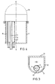
- the apparatus of Figure 4 is mounted vertically.
- One end wall 3 comprises a hemispherical cap 14 having a domed portion of mesh.
- the cap 14 is removable to permit filling the container with e.g. brown rice to be polished and the mesh dome retains the rice when the apparatus is in use but permits inspection of the rotation of the cylinder 6 and the movement of the rice.
- the cap 14 may be removed, the coupling released and the contents of the container emptied for separation of the polished rice from the bran. For the separation, the cap may be used as a sieve.
- the shaft may be inclined to aid the progress of the small objects from the inlet end (if they are supplied at one end) to the outlet end.
- the container may also be inclined, to the same or a different extent 30 the cylinder, or may be horizontal irrespective of any inclination of the cylinder.
- Abrasive material may be applied to the inner wall surface of the chamber, and the shaft may be stationery and the chamber arranged for rotation about the fixed shaft.
Abstract
Description
- This invention concerns apparatus for abrading eg. polishing or scarifying the surface of small objects which may be of wood, plastics, mineral materials or metals. The invention is of particular value in the case of nuts and other seeds eg. cereal seeds, especially rice.
- A variety of forms of apparatus are known for polishing brown rice to remove some or all of the bran coating. Commonly an abrasive rotor is mounted concentrically in a perforate cage. Rice is fed in the annular gap between the rotor and the cage, from an inlet end to an outlet end. Coating, eg. a bran layer, is abraded from the rice grains, and the particles of bran pass through the perforations in the cage.
- Such apparatus tends to be aggressive to the rice grains, at least in part as a result of the grains being forced through the apparatus, and a significant proportion of the grains are broken. This reduces the economic value of the end product. Moreover, is a substantial energy input is required to urge the grains through the apparatus, and the temperature of the rice and of the bran removed is increased which is undesirable.
- According to one aspect of the invention apparatus for use in the abrasive surface treatment of small objects, comprises an elongate chamber with an inlet and an outlet, a shaft mounted in the chamber, means for causing relative rotary movement between the chamber and the shaft, one of the chamber inner wall and/or the shaft having an abrasive surface characterised in that the rotor is eccentrically mounted with respect to the major axis of the chamber.
- Because the shaft is eccentric with respect to the major axis of the chamber, the chamber includes a transverse region of relatively reducing radius. When small objects pass through this region they are subjected to compression, the effect of which is to cause the objects to be abraded to an enhanced degree primarily, because more of the small objects are brought into contact with the abrasive surface. As a result a surface layer on the small objects is removed or abraded off. Preferably the distance between the shaft and the facing inner wall of the chamber is a minimum of slightly more than the smallest dimension of the objects to be treated to a maximum of about ten times that dimension. It is preferred to use the minimum distance to reduce the power requirement.
- It is a much preferred feature of the invention that the chamber wall facing the shaft in the relatively reduced radius region is free of surface deformations the effect of which would be to break small objects while in compression. Such deformations can be present on a perforate wall; according to the invention the defined wall is smooth. The surface material abraded off can be removed through a perforate portion of the chamber wall remote from the relatively reducing region.
- Small objects are readily passed through the apparatus with little input of energy. Because the small objects do not contact an aggressive surface while under compression there are few if any grains broken by the treatment in the apparatus.
- The abrasive treatment may be to remove a surface layer thus rice grains may be polished. The treatment may instead be arranged to damage a surface layer for a subsequent treatment e.g. large or small seeds may be scarified.
- Because the apparatus is of low energy requirement and can be of relatively small volume the apparatus may be supplied in transportable form to agriculturists and the like.
- The abrasive surface may be present on the inner wall of the chamber or on the shaft or both. An abrasive surface present on the shaft may be provided by abrasive stones but it is a preferred feature of the invention that the shaft be provided with a sleeve having a coated abrasive surface. The sleeve may comprise a tube of metal, cardboard, plastics, paper or the like to which is adhered a coating of abrasive grains. The abrasive grains can be selected to give a predetermined degree of sharpness.
- The shaft may take any convenient shape. Usually the shaft will be of generally circular cross-sectional shape but it may be elliptical or otherwise shaped to define the reducing radius region. The shaft may be perforated, either in the reducing radius region or elsewhere along the rotor for the passage of air or other pressurised gas medium to remove surface material abraded off the small objects. The rotor (or the chamber wall) may have baffles or the like to aid the passage of small objects through the apparatus.
- Preferably the small objects are treated dry but water may be present optionally together with additives such as gloss additives.
- The apparatus enables rice or other small objects to be polished or otherwise surface-abraded efficiently and with minimal breakage. Because the lower part of the container walls are continuous ie. not perforate or with surface deformations, the abraded matter (bran in the case of rice) is retained in the container with the objects being polished and appears to exert a cushioning effect, further reducing any tendency for the objects to be broken.
- The apparatus may have a vertically positioned abrasive-surface cylinder mounted to rotate in a generally drum-like container about an axis eccentric with respect the vertical axis of the container. The apparatus may be operated batchwise, the container being filled from the top with the objects and the cylinder rotated for a sufficient time to give the desired degree of polishing. The container can then be emptied and the polished objects separated from the abraded matter.
- In another embodiment the abrasive rotor is mounted for horizontal rotation in a horizontally position drum-like container. Apparatus of this nature can be operated batchwise but is also well suited for continuous operation, the objects being continuously fed in and a mixture of polished objects and abraded matter continuously discharged for subsequent separation. The chamber may be drum like or of channel section having a rounded base and vertical sidewalls. The top of the channel may be a cover, optionally adapted to allow for the removal of material abraded off the small objects.
- The invention is further described with reference to the accompanying diagrammatic drawings in which
- Figure 1 is a longitudinal section through one form of rice polishing apparatus of the invention;
- Figure 2 is a transverse section along lines II-II through the apparatus of Figure 1;
- Figure 3 is a section through another apparatus;
- Figure 4 is a vertical section through another apparatus.
- The same reference numerals are used where possible to describe the different embodiments.
- Referring first to Figures 1 and 2, there is shown an
elongate chamber 1. At one end, the right hand end as shown, the chamber has anend plate 2, and anotherend plate 3 is present at the other end. A shaft 4 extends through the end plates and is held at each end bythrust bearings 5. The shaft is located generally parallel to the major axis X of thechamber 1. Acylindrical body 6 surrounds the shaft 4 and thesurface 7 thereof is covered by abrasive grains e.g. bonded grit. At one end the chamber has aninlet 8 and at the other an outlet 9. - Because the
shaft 2 carrying thebody 6 and thus the abrasive surface ? is eccentrically mounted in the chamber, there are two portions of unequal radius. The portion of relatively reduced radius Rl has a radius equal to about 1 to about TO times the smallest diameter of the objects to be inserted. As shown, there is an entrance R3 of reducing diameter leading into the portion Rl. The wall of thechamber 1 is solid and smooth, especially in the area leading into and including the portion R1. Asieve wall 10 is present at a location outside the solid and smooth area. The shaft 4 is connected, as by belting, to a low horse power motor. - In use, small objects such as hulled rice grains are fed into the
chamber 1 through theinlet 8 until the chamber is at least half full. The motor is switched on and the shaft is rotated to give a surface speed of about 7.5 to 10 metres/second. Because thecylinder 6 has anabrasive surface 7, the rice grains are also caused to rotate. The rice grains are brought from the major radius portion R2 of the chamber to the reducing radius portion R1 where they are compressed. As a result, the surface of the rice grains is well abraded, especially by contact with theabrasive surface 7. The wall portion of the chamber in the region Rl is smooth so that, while under compression the rice grains are not urged against projections likely to break them. As the rice grains continue to rotate they exit from the portion R1 into the major radius portion R2 and the released surface material may be drawn off via thecrating 10. - The apparatus shown in Figure 3 is the same as that of Figures 1 and 2 but the
container 3 is of a channel section eg. having a semicircular-base 11,upright sidewalls 12 and a flat top hingedcover 13. The small objects are inserted, thecover 13 lowered and after operation, the mixture of grains and bran is removed and the components then separated. In this case, the mouth of the chamber serves as both inlet and outlet. In a modification thecover 13 is perforated, and the bran is removed therethrough. - The apparatus of Figure 4 is mounted vertically. One
end wall 3 comprises ahemispherical cap 14 having a domed portion of mesh. Thecap 14 is removable to permit filling the container with e.g. brown rice to be polished and the mesh dome retains the rice when the apparatus is in use but permits inspection of the rotation of thecylinder 6 and the movement of the rice. When the rice is sufficiently polished, thecap 14 may be removed, the coupling released and the contents of the container emptied for separation of the polished rice from the bran. For the separation, the cap may be used as a sieve. - The apparatus is not limited to the embodiments shown. For example, the shaft may be inclined to aid the progress of the small objects from the inlet end (if they are supplied at one end) to the outlet end. The container may also be inclined, to the same or a different extent 30 the cylinder, or may be horizontal irrespective of any inclination of the cylinder. Abrasive material may be applied to the inner wall surface of the chamber, and the shaft may be stationery and the chamber arranged for rotation about the fixed shaft.
Claims (10)
Applications Claiming Priority (2)
| Application Number | Priority Date | Filing Date | Title |
|---|---|---|---|
| GB858529533A GB8529533D0 (en) | 1985-11-30 | 1985-11-30 | Treatment of particles |
| GB8529533 | 1985-11-30 |
Publications (2)
| Publication Number | Publication Date |
|---|---|
| EP0225765A2 true EP0225765A2 (en) | 1987-06-16 |
| EP0225765A3 EP0225765A3 (en) | 1989-05-24 |
Family
ID=10589051
Family Applications (1)
| Application Number | Title | Priority Date | Filing Date |
|---|---|---|---|
| EP86309215A Withdrawn EP0225765A3 (en) | 1985-11-30 | 1986-11-26 | Apparatus for abrading small objects |
Country Status (5)
| Country | Link |
|---|---|
| EP (1) | EP0225765A3 (en) |
| JP (1) | JPS62173163A (en) |
| CN (1) | CN86108711A (en) |
| BR (1) | BR8605845A (en) |
| GB (1) | GB8529533D0 (en) |
Cited By (3)
| Publication number | Priority date | Publication date | Assignee | Title |
|---|---|---|---|---|
| GB2249043A (en) * | 1990-09-27 | 1992-04-29 | Alexander Stephen Anderson | Surface abrasive treatment of small objects |
| EP0572850A1 (en) * | 1992-06-05 | 1993-12-08 | Bühler Ag | Device for post-treatment of pellets |
| GB2289004A (en) * | 1994-04-22 | 1995-11-08 | Koolmill Systems Ltd | Abrading small objects eg. seeds using a rotating vertical abrasive drum |
Families Citing this family (2)
| Publication number | Priority date | Publication date | Assignee | Title |
|---|---|---|---|---|
| CN1962067B (en) * | 2005-11-10 | 2010-04-14 | 鸿富锦精密工业(深圳)有限公司 | Milling equipment |
| FR3026967B1 (en) * | 2014-10-10 | 2016-10-28 | Fives Fcb | COMPRESSOR BINDER OF BED OF MATERIALS |
Citations (7)
| Publication number | Priority date | Publication date | Assignee | Title |
|---|---|---|---|---|
| DE82320C (en) * | ||||
| DE215400C (en) * | ||||
| DE138272C (en) * | ||||
| DE73035C (en) * | A. EHRESMANN und H. EHRESMANN in Kaiserslautern | Fruit cleaning and peeling machine | ||
| DE856400C (en) * | 1951-02-11 | 1952-11-20 | Wilhelm Schmieg | Grain and fine seed peeling, brushing and grinding machine |
| US3606918A (en) * | 1969-03-13 | 1971-09-21 | Sofronio M Sian | Portable cone type rice mill |
| GB1318973A (en) * | 1969-06-24 | 1973-05-31 | Yanmar Diesel Engine Co | Polishing rolls assembly |
-
1985
- 1985-11-30 GB GB858529533A patent/GB8529533D0/en active Pending
-
1986
- 1986-11-26 EP EP86309215A patent/EP0225765A3/en not_active Withdrawn
- 1986-11-28 BR BR8605845A patent/BR8605845A/en unknown
- 1986-11-28 JP JP28408686A patent/JPS62173163A/en active Pending
- 1986-11-30 CN CN198686108711A patent/CN86108711A/en active Pending
Patent Citations (7)
| Publication number | Priority date | Publication date | Assignee | Title |
|---|---|---|---|---|
| DE82320C (en) * | ||||
| DE215400C (en) * | ||||
| DE138272C (en) * | ||||
| DE73035C (en) * | A. EHRESMANN und H. EHRESMANN in Kaiserslautern | Fruit cleaning and peeling machine | ||
| DE856400C (en) * | 1951-02-11 | 1952-11-20 | Wilhelm Schmieg | Grain and fine seed peeling, brushing and grinding machine |
| US3606918A (en) * | 1969-03-13 | 1971-09-21 | Sofronio M Sian | Portable cone type rice mill |
| GB1318973A (en) * | 1969-06-24 | 1973-05-31 | Yanmar Diesel Engine Co | Polishing rolls assembly |
Cited By (5)
| Publication number | Priority date | Publication date | Assignee | Title |
|---|---|---|---|---|
| GB2249043A (en) * | 1990-09-27 | 1992-04-29 | Alexander Stephen Anderson | Surface abrasive treatment of small objects |
| GB2249043B (en) * | 1990-09-27 | 1994-05-11 | Alexander Stephen Anderson | Surface abrasive treatment of small objects |
| EP0572850A1 (en) * | 1992-06-05 | 1993-12-08 | Bühler Ag | Device for post-treatment of pellets |
| GB2289004A (en) * | 1994-04-22 | 1995-11-08 | Koolmill Systems Ltd | Abrading small objects eg. seeds using a rotating vertical abrasive drum |
| GB2289004B (en) * | 1994-04-22 | 1997-08-20 | Koolmill Systems Ltd | Surface abrasive treatment of small objects |
Also Published As
| Publication number | Publication date |
|---|---|
| GB8529533D0 (en) | 1986-01-08 |
| BR8605845A (en) | 1987-08-25 |
| CN86108711A (en) | 1987-06-17 |
| JPS62173163A (en) | 1987-07-30 |
| EP0225765A3 (en) | 1989-05-24 |
Similar Documents
| Publication | Publication Date | Title |
|---|---|---|
| US5048407A (en) | Grain husking and polishing machine | |
| EP0225765A2 (en) | Apparatus for abrading small objects | |
| US5706879A (en) | Process for the reclamation of used foundry sand | |
| US5830042A (en) | Surface abrasive treatment of small objects | |
| US3955608A (en) | Debarking method and apparatus | |
| JP2620854B2 (en) | Method and apparatus for performing separation of spherical materials of various sizes or shapes | |
| FI75746C (en) | Apparatus for separating dry subsenses varying in particle form. | |
| US3436868A (en) | Rounding and polishing apparatus for crystalline carbon bodies | |
| US4001984A (en) | Method for finishing parts | |
| KR100501712B1 (en) | Method and device for crushing of bulk materials | |
| JPH08318172A (en) | Crushing device for glass and the like and method for finely crushing glass and the like | |
| SU1736605A1 (en) | Apparatus for crushing materials | |
| SU1263343A1 (en) | Apparatus for crushing material | |
| GB1472573A (en) | Abrading methods and abrading apparatus | |
| AU690669C (en) | Surface abrasive treatment of small objects | |
| RU2014894C1 (en) | Grinder | |
| RU21153U1 (en) | VIBRATION MILL | |
| RU20259U1 (en) | LARGE MACHINE | |
| SU927308A1 (en) | Washing machine | |
| SU988337A1 (en) | Scrubber for washing minerals | |
| SU1230685A1 (en) | Laboratory vibratory mill | |
| SU1741893A1 (en) | Centrifugal mill | |
| SU1685722A1 (en) | Method of grinding of worn tyres | |
| SU1563748A1 (en) | Arrangement for grinding materials | |
| GB2249018A (en) | Grain husking and polishing machine |
Legal Events
| Date | Code | Title | Description |
|---|---|---|---|
| PUAI | Public reference made under article 153(3) epc to a published international application that has entered the european phase |
Free format text: ORIGINAL CODE: 0009012 |
|
| AK | Designated contracting states |
Kind code of ref document: A2 Designated state(s): DE ES GB IT |
|
| RAP1 | Party data changed (applicant data changed or rights of an application transferred) |
Owner name: UNICORN INDUSTRIES PLC |
|
| PUAL | Search report despatched |
Free format text: ORIGINAL CODE: 0009013 |
|
| AK | Designated contracting states |
Kind code of ref document: A3 Designated state(s): DE ES GB IT |
|
| STAA | Information on the status of an ep patent application or granted ep patent |
Free format text: STATUS: THE APPLICATION IS DEEMED TO BE WITHDRAWN |
|
| 18D | Application deemed to be withdrawn |
Effective date: 19890531 |
|
| RIN1 | Information on inventor provided before grant (corrected) |
Inventor name: TAINSH, JOHN ARCHIBALD RAMSAY Inventor name: BURSEY, EDWARD CHARLES |