EP0225620B1 - Multicylinder internal-combustion engine having an intake system - Google Patents
Multicylinder internal-combustion engine having an intake system Download PDFInfo
- Publication number
- EP0225620B1 EP0225620B1 EP86116966A EP86116966A EP0225620B1 EP 0225620 B1 EP0225620 B1 EP 0225620B1 EP 86116966 A EP86116966 A EP 86116966A EP 86116966 A EP86116966 A EP 86116966A EP 0225620 B1 EP0225620 B1 EP 0225620B1
- Authority
- EP
- European Patent Office
- Prior art keywords
- resonance
- combustion engine
- internal combustion
- collector
- tubes
- Prior art date
- Legal status (The legal status is an assumption and is not a legal conclusion. Google has not performed a legal analysis and makes no representation as to the accuracy of the status listed.)
- Expired
Links
Images


Classifications
-
- F—MECHANICAL ENGINEERING; LIGHTING; HEATING; WEAPONS; BLASTING
- F02—COMBUSTION ENGINES; HOT-GAS OR COMBUSTION-PRODUCT ENGINE PLANTS
- F02B—INTERNAL-COMBUSTION PISTON ENGINES; COMBUSTION ENGINES IN GENERAL
- F02B27/00—Use of kinetic or wave energy of charge in induction systems, or of combustion residues in exhaust systems, for improving quantity of charge or for increasing removal of combustion residues
- F02B27/02—Use of kinetic or wave energy of charge in induction systems, or of combustion residues in exhaust systems, for improving quantity of charge or for increasing removal of combustion residues the systems having variable, i.e. adjustable, cross-sectional areas, chambers of variable volume, or like variable means
- F02B27/0226—Use of kinetic or wave energy of charge in induction systems, or of combustion residues in exhaust systems, for improving quantity of charge or for increasing removal of combustion residues the systems having variable, i.e. adjustable, cross-sectional areas, chambers of variable volume, or like variable means characterised by the means generating the charging effect
- F02B27/0247—Plenum chambers; Resonance chambers or resonance pipes
- F02B27/0252—Multiple plenum chambers or plenum chambers having inner separation walls, e.g. comprising valves for the same group of cylinders
-
- F—MECHANICAL ENGINEERING; LIGHTING; HEATING; WEAPONS; BLASTING
- F02—COMBUSTION ENGINES; HOT-GAS OR COMBUSTION-PRODUCT ENGINE PLANTS
- F02B—INTERNAL-COMBUSTION PISTON ENGINES; COMBUSTION ENGINES IN GENERAL
- F02B27/00—Use of kinetic or wave energy of charge in induction systems, or of combustion residues in exhaust systems, for improving quantity of charge or for increasing removal of combustion residues
- F02B27/02—Use of kinetic or wave energy of charge in induction systems, or of combustion residues in exhaust systems, for improving quantity of charge or for increasing removal of combustion residues the systems having variable, i.e. adjustable, cross-sectional areas, chambers of variable volume, or like variable means
- F02B27/0205—Use of kinetic or wave energy of charge in induction systems, or of combustion residues in exhaust systems, for improving quantity of charge or for increasing removal of combustion residues the systems having variable, i.e. adjustable, cross-sectional areas, chambers of variable volume, or like variable means characterised by the charging effect
- F02B27/021—Resonance charging
-
- F—MECHANICAL ENGINEERING; LIGHTING; HEATING; WEAPONS; BLASTING
- F02—COMBUSTION ENGINES; HOT-GAS OR COMBUSTION-PRODUCT ENGINE PLANTS
- F02B—INTERNAL-COMBUSTION PISTON ENGINES; COMBUSTION ENGINES IN GENERAL
- F02B27/00—Use of kinetic or wave energy of charge in induction systems, or of combustion residues in exhaust systems, for improving quantity of charge or for increasing removal of combustion residues
- F02B27/02—Use of kinetic or wave energy of charge in induction systems, or of combustion residues in exhaust systems, for improving quantity of charge or for increasing removal of combustion residues the systems having variable, i.e. adjustable, cross-sectional areas, chambers of variable volume, or like variable means
- F02B27/0205—Use of kinetic or wave energy of charge in induction systems, or of combustion residues in exhaust systems, for improving quantity of charge or for increasing removal of combustion residues the systems having variable, i.e. adjustable, cross-sectional areas, chambers of variable volume, or like variable means characterised by the charging effect
- F02B27/0215—Oscillating pipe charging, i.e. variable intake pipe length charging
- F02B27/0221—Resonance charging combined with oscillating pipe charging
-
- F—MECHANICAL ENGINEERING; LIGHTING; HEATING; WEAPONS; BLASTING
- F02—COMBUSTION ENGINES; HOT-GAS OR COMBUSTION-PRODUCT ENGINE PLANTS
- F02B—INTERNAL-COMBUSTION PISTON ENGINES; COMBUSTION ENGINES IN GENERAL
- F02B27/00—Use of kinetic or wave energy of charge in induction systems, or of combustion residues in exhaust systems, for improving quantity of charge or for increasing removal of combustion residues
- F02B27/02—Use of kinetic or wave energy of charge in induction systems, or of combustion residues in exhaust systems, for improving quantity of charge or for increasing removal of combustion residues the systems having variable, i.e. adjustable, cross-sectional areas, chambers of variable volume, or like variable means
- F02B27/0226—Use of kinetic or wave energy of charge in induction systems, or of combustion residues in exhaust systems, for improving quantity of charge or for increasing removal of combustion residues the systems having variable, i.e. adjustable, cross-sectional areas, chambers of variable volume, or like variable means characterised by the means generating the charging effect
- F02B27/0268—Valves
- F02B27/0273—Flap valves
-
- F—MECHANICAL ENGINEERING; LIGHTING; HEATING; WEAPONS; BLASTING
- F02—COMBUSTION ENGINES; HOT-GAS OR COMBUSTION-PRODUCT ENGINE PLANTS
- F02B—INTERNAL-COMBUSTION PISTON ENGINES; COMBUSTION ENGINES IN GENERAL
- F02B27/00—Use of kinetic or wave energy of charge in induction systems, or of combustion residues in exhaust systems, for improving quantity of charge or for increasing removal of combustion residues
- F02B27/02—Use of kinetic or wave energy of charge in induction systems, or of combustion residues in exhaust systems, for improving quantity of charge or for increasing removal of combustion residues the systems having variable, i.e. adjustable, cross-sectional areas, chambers of variable volume, or like variable means
- F02B27/0226—Use of kinetic or wave energy of charge in induction systems, or of combustion residues in exhaust systems, for improving quantity of charge or for increasing removal of combustion residues the systems having variable, i.e. adjustable, cross-sectional areas, chambers of variable volume, or like variable means characterised by the means generating the charging effect
- F02B27/0289—Intake runners having multiple intake valves per cylinder
-
- F—MECHANICAL ENGINEERING; LIGHTING; HEATING; WEAPONS; BLASTING
- F02—COMBUSTION ENGINES; HOT-GAS OR COMBUSTION-PRODUCT ENGINE PLANTS
- F02B—INTERNAL-COMBUSTION PISTON ENGINES; COMBUSTION ENGINES IN GENERAL
- F02B75/00—Other engines
- F02B75/16—Engines characterised by number of cylinders, e.g. single-cylinder engines
- F02B75/18—Multi-cylinder engines
- F02B2075/1804—Number of cylinders
- F02B2075/1824—Number of cylinders six
-
- Y—GENERAL TAGGING OF NEW TECHNOLOGICAL DEVELOPMENTS; GENERAL TAGGING OF CROSS-SECTIONAL TECHNOLOGIES SPANNING OVER SEVERAL SECTIONS OF THE IPC; TECHNICAL SUBJECTS COVERED BY FORMER USPC CROSS-REFERENCE ART COLLECTIONS [XRACs] AND DIGESTS
- Y02—TECHNOLOGIES OR APPLICATIONS FOR MITIGATION OR ADAPTATION AGAINST CLIMATE CHANGE
- Y02T—CLIMATE CHANGE MITIGATION TECHNOLOGIES RELATED TO TRANSPORTATION
- Y02T10/00—Road transport of goods or passengers
- Y02T10/10—Internal combustion engine [ICE] based vehicles
- Y02T10/12—Improving ICE efficiencies
Definitions
- the invention is based on the preamble of the independent claim from JP-A 59/82523.
- the intake system As a resonance system with resonance tubes and resonance containers.
- the resonance containers are connected via suction lines to groups of combustion chambers with the same ignition or injection intervals, as is shown and described, for example, in DE-C 1 935 155 for a 6-cylinder internal combustion engine equipped with an exhaust gas turbocharger.
- an intake system for a multi-cylinder internal combustion engine is known from JP-A 56 115 818, in which an oscillating tube system is combined with a resonance system.
- the collector provided for the vibrating tube system is divided into two volumes by means of a controllable throttle valve, which serve as a resonance volume or as a resonance container.
- the vibrating tube system combined with a resonance system has only one suction line to each combustion chamber of the multi-cylinder internal combustion engine.
- Systems of this type show a first favorable curve profile for the air expenditure in a transition area from lower to medium speeds and also a second favorable curve profile for the air expenditure in the upper speed range.
- the invention is therefore based on the object of developing a multi-cylinder internal combustion engine in such a way that the air expenditure is improved from the lower to the upper operating range.
- the basic idea of the invention is to generate different resonances in the resonance system in a multi-cylinder internal combustion engine with an intake system combined from a vibrating tube system and a resonance system by means of several vibrating tubes which can be switched on and / or off depending on the operating point and are provided for each combustion chamber or cylinder.
- adjacent resonance ranges are advantageously achieved in terms of speed. This extends the effective range of the resonance system from a relatively narrow speed range to a much larger speed range.
- the two resonance containers are short-circuited, i.e. the two resonance volumes are combined to form the collector volume.
- the influence on the combined intake system in the case of exclusively vibrating pipe operation can be minimized in such a way that a vibrating pipe charge subsequent to the resonance charging is achieved with only first vibrating pipes of the combustion chambers or cylinders, a flat course of the air expenditure curve close to "1".
- Relatively long vibrating tubes of relatively small cross-section are preferably preferred for this vibrating tube supercharging in the middle speed range of the internal combustion engine. This is the one in St.d.T. Typical slump between resonance charging in the lower speed range and vibrating tube charging in the upper speed range avoided.
- At least one further second oscillating tube of at least a relatively large cross section is connected for each combustion chamber or cylinder.
- Switching on the second vibrating tubes means a changed vibration behavior for all openly controlled vibrating tubes due to the relatively shorter vibrating tubes compared to the long vibrating tubes, as the latter is known per se for high speeds.
- the enlarged effective resonance cross section results in a shift in the resonance frequency to higher speeds, which further improves the air consumption in the second half of the lower speed range towards the lower middle speed range.
- the further course of the air expenditure curve for the middle and upper speed range is again essentially effected via the oscillating tubes and its characteristics are essentially identical to the curve course of the embodiment according to claims 1 and 2.
- a preferred embodiment with regard to the construction with respect to the others Embodiment of the invention is described in more detail in claims 5 and 6.
- the short-circuiting of the resonance tank described in claim 6 via intake manifold connected to the expansion tank, together with the weakening of the resonance vibration with increasing engine speed, causes the resonance frequency to be shifted outside the desired speed range.
- the fresh air drawn in flows to the large via the short and preferably large-diameter intake ports, so that the resonance pipes are shunted and, controlled or not controlled, have no influence on the vibration behavior of the vibrating pipes.
- a multi-cylinder internal combustion engine with an intake system according to the invention additionally has a gas exchange control device with an intersection of inlet and outlet.
- the overlap can be used to flush the combustion chamber.
- the gas exchange control device preferably for exhaust valves has a separate control shaft with a control shaft adjusting device for changing the phase position of the control shaft relative to the crankshaft, then the extent of the overlap can be changed on the outlet side depending on the operating point, in particular depending on the speed.
- the multi-cylinder internal combustion engine with the intake system according to the invention and / or the above-described gas exchange control device can additionally be equipped with a charger.
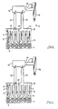
- a 6-cylinder in-line internal combustion engine 1 is equipped with an intake system 2, which is formed from a vibrating tube system 3 and a resonance system 4.
- an intake system 2 which is formed from a vibrating tube system 3 and a resonance system 4.
- two oscillating tubes 6 and 7 are assigned to each combustion chamber 5 of the internal combustion engine 1.
- the first and second vibrating tubes 6 and 7 are connected to a collector 8 at the end remote from the engine.
- the second vibrating tubes 7 are of relatively large diameter and relatively short.
- the first vibrating tubes 6, are of relatively small diameter and relatively long length, which is preferably achieved by an arcuate course between the respective combustion chamber 5 and the collector 8.
- a shut-off element 9 is arranged near the combustion chamber.
- the collector 8 can be divided by a shut-off device 10 into two resonance containers 11 and 12 of the same volume.
- the two resonance tanks 11 and 12 are each connected to three combustion chambers 5 of the internal combustion engine 1 via the first and second oscillating tubes 6 and 7, with a suction sequence of 240 ° KW being given in each group of the three combustion chambers 5.
- Tubes 13 and 14 connected, which serve as resonance tubes when the collector 8 is divided into the resonance containers 11 and 12.
- the resonance tubes 13 and 14 cooperate with an expansion tank 15, which is formed with an independently controlled air inlet 16.
- An air flow meter 17 and an intake silencer 18 are arranged upstream of the air inlet 16.
- the collector shut-off device 10 and the oscillating pipe shut-off devices 9 are controlled relative to the independently controlled air inlet 16 either in the same direction or alternately in opposite directions by means of a computer, depending on the operating point. With appropriate control of the aforementioned shut-off devices, an improved resonance charging in the lower speed range of the internal combustion engine 1 is thus achieved.
- the improved resonance charging is shown in FIG. 9 on the basis of the solid curve for the air expenditure, the dotted curve corresponding to the air expenditure of an intake system formed in a conventional manner from a vibrating tube system and a resonance system.
- the solid curve representing the course of the air expenditure over the entire speed range of the internal combustion engine 1 at full load comprises first curve sections A and B, which are achieved by resonance charging.
- the natural frequency of the resonance containers 11 and 12 and the resonance tubes 13 and 14 connected to them is tuned for the lowest speed range of the internal combustion engine 1.
- the resonance containers 11 and 12 each have a defined volume, the resonance tubes 13 and 14 each having a specific length and a specific diameter.
- the second, short vibrating pipes 7 are closed by the shut-off elements 9.
- the resonance oscillation propagates to the respective combustion chamber 5 only via the first longer oscillating tube 6 with a small cross section.
- Each vibrating tube 6 is designed in terms of its length and its cross section with a view to a relatively small volume in order to dampen the resonance vibration as little as possible.
- the shut-off elements 9 of the second short oscillating tubes 7 are additionally opened according to FIG. 2.
- the fresh air drawn in thus flows to the respective combustion chamber 5 via a considerably enlarged cross-section of the oscillating tube.
- Switching on the second vibrating tubes 7 causes the resonance to be shifted to higher speeds of the internal combustion engine 1.
- Corresponding tuning of the vibrating tubes in their geometrical dimensions results in a curved portion B following the curved portion A without significant breakdown.
- the resonance vibration weakens.
- the two resonance containers 11 and 12 are connected to one another by opening the shut-off element 10 according to FIG. 3.
- the vibrating tube shut-off elements 9 are moved in opposite directions relative to the collector shut-off element 10 in order to close the second, short vibrating tubes 7.
- the fresh air therefore flows to each combustion chamber 5 exclusively via the first, relatively long oscillating tube 6 of relatively small cross-section.
- the relatively small pipe cross-section causes a high flow rate.
- a certain reloading effect is brought about with the relatively long oscillating tubes 6 towards the inlet end.
- the length of the vibrating tubes 6 is of further importance for high air expenditure in the medium speed range. Since the length and diameter of the vibrating tubes 6 is also important for the speed range corresponding to curve A with resonance charging; A compromise must be found with regard to the respective length of the vibrating tubes 6, which results in a high air expenditure both in the lower speed range corresponding to the curve section and in the middle speed range corresponding to curve section A.
- Each suction process triggered in a combustion chamber 5 causes a suction wave migrating against the incoming fresh air in the connected, open oscillating tube 6 or 7.
- Such a suction wave triggers such a natural vibration in the lower speed range in the resonance system 4 switched according to FIGS. 1 and 2 that a resonance pressure wave is present at the open inlet.
- the diameter of the relatively long vibrating tubes 6 is particularly important for this.
- the suction wave reflected at the open tube end is applied as a pressure wave at the open inlet and thus acts to promote filling.
- the second, short oscillation tubes 7 are connected to the first, long oscillation tubes 6 by opening the shut-off elements 9.
- the 6-cylinder in-line internal combustion engine 19 with combustion chambers 20 shown in FIG. 5 with 8 is included 1 with 4 modified intake system 21 compared to the internal combustion engine 1 of FIG. 1, by means of which the air expenditure and thus the combustion chamber filling can be increased further in the lower speed range, as shown by the dashed curve in FIG. 9.
- Each combustion chamber 20 of the internal combustion engine 19 is connected to two oscillating tubes 22 and 23.
- Each first oscillating tube 22 is of an arcuate shape of relatively great length (not shown in the drawing) and has a relatively small cross section.
- every second vibrating tube 23 is relatively short and has a relatively large cross section.
- a shut-off device 24 is assigned to each short oscillating tube 23 near the combustion chamber.
- the first, long oscillating tubes 22 are connected to a collector 25.
- a collector 25 Structurally adjacent to the collector 25 is an expansion tank 26 with which the second, short oscillating tubes 23 are connected in an air-guiding manner.
- the expansion tank 26 has an independently controllable air inlet 27 which is connected upstream to an air quantity or air mass meter 28 and an intake silencer 29.
- the collector 25 divides a partition 30 into the resonance containers 31 and 32. Furthermore, the collector 25 in the region of each resonance container 31 and 32 each has an intake port 33 and 34 connected to the compensating container 26. Each of the intake ports 33, 34 is equipped with a shut-off device 35.
- the resonance tanks 31 and 32 are each connected to the expansion tank 26 via a long resonance tube 36 and a short resonance tube 37.
- the short resonance pipes 37 are each equipped with a shut-off device 38 at the confluence with the resonance containers 31 and 32.
- the cross section of the resonance pipes 13, 14 is in each case in smaller cross sections for several Resonance tubes 36, 37 divided into a resonance container 31, 32.
- the resonance tubes 36 and 37 are of different lengths, the relatively shorter resonance tubes 37 being closable in a controlled manner by the shut-off device 38 depending on the operating point.
- a cross section is sought in addition to a relatively large length, which is approximately the cross section of the first, long one Vibration tubes 22 corresponds.
- This large pipe length with a relatively small cross section brings about a considerable increase in the air expenditure at the lowest speeds, as is shown by the curve section A 'in FIG. 9. 5, the shut-off elements 35 in the intake ports 33, 34, the shut-off elements 38 in the short resonance tubes 37 and finally the shut-off elements 24 of the second short oscillating tubes 23 are brought under computer control into the closed position.
- the shut-off elements 38 are brought into the open position in the short resonance tubes 37. This increases the effective resonance tube cross section. Due to the different lengths of the resonance tubes 36 and 37, in conjunction with the enlarged effective resonance cross section, there is a shift in the resonance frequency to higher speeds according to the curve section B 'in FIG. 9. As can be seen from FIG. 6, the shut-off elements 35 are in this resonance charge the intake manifold 33 and 34 and the shut-off devices 24 of the short swing pipes in the closed position.
- the resonance oscillation weakens and the intake system 21 is therefore switched over from the resonance charging to the oscillating tube charging.
- the shut-off devices 35 in the intake ports 33 and 34 are brought into the open position.
- the resonance tanks 31 and 32, which each form one half of the collector 25, are thus short-circuited via the structurally adjacent expansion tank 26, whereby the collector 25 assumes its function in the oscillating tube system 40 due to the excitation frequency reduced from 240 ° KW to 120 ° KW.
- the fresh air is therefore largely supplied to the combustion chambers 20 of the internal combustion engine 19 via the open intake ports 33 and 34, the collector 25 and the first, long oscillating tubes 22.
- the second, short oscillating tubes 23 are switched on by opening the shut-off elements 24.
- shorter vibrating tubes are achieved in their effective length with the effect of a displacement of the vibrating tube charging to higher speeds.
- the corresponding course of the air expenditure therefore again essentially corresponds to the curve section D in FIG. 9.
- the air expenditure can also be further improved in resonance mode if internal combustion engines 1 and 19 are each equipped with a gas exchange control device which has or enables an overlap of inlet and outlet.
- a gas exchange control device which has or enables an overlap of inlet and outlet.
- the resonance pressure wave present at the open inlet can purge the combustion chamber via the just open outlet and then with the outlet closed lead to an increase in the load.
- the increase in the cylinder charge is additionally caused by reduced backflow losses before the intake closure between the UT and the intake control.
- Such a gas exchange control causes an internal combustion engine 1 or 19 to shift the curve pieces A and B 'in the direction of the air expenditure value "1".
- each of the internal combustion engines designed according to the invention can be equipped with a charger.
- any internal combustion engine equipped according to the invention can also suck in freely from the ambient air via the resonance pipes, a resonance pipe of each resonance system then simultaneously forming an independently controlled air inlet.
Description
Die Erfindung geht gemäß dem Oberbegriff des unabhängigen Patentanspruches von der JP-A 59/82523 aus.The invention is based on the preamble of the independent claim from JP-A 59/82523.
Bei dieser bekannten Bauart sind einem Brennraum zwei Schwingrohre mit unterschiedlichen geometrischen Abmessungen zugeordnet, die mittels steuerbarer Absperrorgane einzeln oder gemeinsam wirken. Bekanntlich dienen Schwingrohr-Systeme zur Steigerung des Luftaufwandes und damit zur Anhebung des Drehmomentes einer Brennkraftmaschine.In this known design, two vibrating tubes with different geometric dimensions are assigned to a combustion chamber, which act individually or together by means of controllable shut-off elements. As is known, vibrating tube systems serve to increase the air expenditure and thus to increase the torque of an internal combustion engine.
Da bei in Fahrzeugen eingebauten Brennkraftmaschinen die Platzverhältnisse eine Ansauganlage mit in der Länge deutlich unterschiedlichen Schwingrohren nicht ohne weiteres zulassen, sind die Scheitel günstiger Kurvenverläufe für Luftaufwand bzw. Drehmoment hinsichtlich des Drehzahlabstandes relativ eng benachbart. Weiter ist es bekannt, Schwingrohr-Systeme, insbesondere für mittlere und hohe Drehzahlbereiche, zur Verbesserung des Luftaufwandes einzusetzen, wie dies z.B. GB-A 1 136 961 ausweist.Since the space available in internal combustion engines installed in vehicles does not readily allow an intake system with oscillating tubes that are significantly different in length, the apexes of favorable curves for air expenditure or torque are relatively closely adjacent in terms of the speed difference. It is also known to use vibrating tube systems, in particular for medium and high speed ranges, to improve the air expenditure, as is the case e.g. GB-A 1 136 961.
Zur Steigerung des Luftaufwandes bei niedrigen Drehzahlen der Brennkraftmaschine ist es bekannt, die Ansauganlage als Resonanzsystem mit Resonanzrohren und Resonanzbehältern auszubilden. Bei einer Mehrzylinder-Brennkraftmaschine stehen die Resonanzbehälter über Saugleitungen mit Gruppen von Brennräumen mit gleichen Zünd-oder Einspritzabständen in Verbindung, wie dies beispielsweise in der DE-C 1 935 155 für eine mit einem Abgasturbolader ausgerüstete 6-Zylinder-Brennkraftmaschine gezeigt und beschrieben ist.To increase the air expenditure at low engine speeds, it is known to design the intake system as a resonance system with resonance tubes and resonance containers. In a multi-cylinder internal combustion engine, the resonance containers are connected via suction lines to groups of combustion chambers with the same ignition or injection intervals, as is shown and described, for example, in DE-C 1 935 155 for a 6-cylinder internal combustion engine equipped with an exhaust gas turbocharger.
Schließlich ist aus der JP-A 56 115 818 eine Ansauganlage für eine Mehrzylinder-Brennkraftmaschine bekannt, bei der ein Schwingrohr-System mit einem Resonanzsystem kombiniert ist. Zur baulichen Vereinfachung einer derartigen Anlage wird der für das Schwingrohr-System vorgesehene Sammler mittels einer steuerbaren Drosselklappe in zwei Volumina unterteilt, die als Resonanzvolumen bzw. als Resonanzbehälter dienen. Im Gegensatz zu dem eingangs genannten Schwingrohr-System weist das mit einem Resonanzsystem kombinierte Schwingrohr-System jeweils nur eine Saugleitung zu jedem Brennraum der Mehrzylinder-Brennkraftmaschine auf. Derartige Anlagen zeigen einen ersten günstigen Kurvenverlauf für den Luftaufwand in einem Übergangsbereich von unteren zu mittleren Drehzahlen auf und ferner einen zweiten günstigen Kurvenverlauf für den Luftaufwand im oberen Drehzahlbereich. Im gesamten Kurvenverlauf für den Luftaufwand liegen diese günstigen Wertbereiche drehzahlmäßig relativ weit auseinander mit einem dazwischen liegenden Einbruch. Weiter zeigt der Kurvenverlauf einen relativ steilen Abfall im mittleren niederen Drehzahlbereich. Einen charakteristischen Drehmoment-Kurvenverlauf zeigt im übrigen Bild 2 auf Seite 437 im Heft 10 der ATZ von 1984 für eine vorbeschriebene kombinierte Ansauganlage.Finally, an intake system for a multi-cylinder internal combustion engine is known from JP-A 56 115 818, in which an oscillating tube system is combined with a resonance system. To simplify the construction of such a system, the collector provided for the vibrating tube system is divided into two volumes by means of a controllable throttle valve, which serve as a resonance volume or as a resonance container. In contrast to the above-mentioned vibrating tube system, the vibrating tube system combined with a resonance system has only one suction line to each combustion chamber of the multi-cylinder internal combustion engine. Systems of this type show a first favorable curve profile for the air expenditure in a transition area from lower to medium speeds and also a second favorable curve profile for the air expenditure in the upper speed range. In the entire course of the curve for the air expenditure, these favorable value ranges are relatively far apart in terms of speed with a drop in between. The curve also shows a relatively steep drop in the middle low speed range. A characteristic torque curve profile is shown in the rest of Figure 2 on page 437 in
Der Erfindung liegt deshalb die Aufgabe zugrunde, eine Mehrzylinder-Brennkraftmaschine so weiterzubilden, daß der Luftaufwand vom unteren bis in den oberen Betriebsbereich hinein verbessert ist.The invention is therefore based on the object of developing a multi-cylinder internal combustion engine in such a way that the air expenditure is improved from the lower to the upper operating range.
Diese Aufgabe wird mit den kennzeichnenden Merkmalen des unabhängigen Patentanspruches gelöst. Grundgedanke der Erfindung ist, bei einer Mehrzylinder-Brennkraftmaschine mit einer aus einem Schwingrohr-System und einem Resonanzsystem kombinierten Ansauganlage durch mehrere je Brennraum bzw. Zylinder vorgesehene, betriebspunktabhängig zu- und/oder abschaltbare Schwingrohre im Resonanz-System unterschiedliche Resonanzen zu erzeugen. Durch geometrische Abstimmung beider Systeme werden dadurch in vorteilhafter Weise drehzahlmäßig benachbarte Resonanzbereiche erzielt. Damit wird der Wirkungsbereich des Resonanz-Systems von einem relativ schmalen Drehzahlbereich auf einen wesentlich größeren Drehzahlbereich erweitert. Die Anwendung der erfindungsgemäßen Resonanz-Aufladung über den unteren und bis in den mittleren Drehzahlbereich der Brennkraftmaschine hinein ergibt bereits im mittleren unteren Drehzahlbereich einen steilen Anstieg im Kurvenverlauf des Luftaufwandes, wobei der Kurvenverlauf im angrenzenden Drehzahlbereich etwa auf gleich Höhe bleibend nahe dem Luftaufwand-Wert "1" verläuft.This object is achieved with the characterizing features of the independent claim. The basic idea of the invention is to generate different resonances in the resonance system in a multi-cylinder internal combustion engine with an intake system combined from a vibrating tube system and a resonance system by means of several vibrating tubes which can be switched on and / or off depending on the operating point and are provided for each combustion chamber or cylinder. By geometrically coordinating the two systems, adjacent resonance ranges are advantageously achieved in terms of speed. This extends the effective range of the resonance system from a relatively narrow speed range to a much larger speed range. The application of the resonance supercharger according to the invention over the lower and up to the middle speed range of the internal combustion engine results in a steep increase in the course of the curve of the air expenditure even in the middle lower speed range, the course of the curve in the adjacent speed range remaining approximately at the same level close to the air expenditure value " 1 "runs.
Mit zunehmender Last und Drehzahl werden die beiden Resonanzbehälter miteinander kurzgeschlossen, d.h., die beiden Resonanz-Volumina werden zum Sammlervolumen vereint. Bei entsprechender Wahl der geometrischen Abmessungen der Resonanzrohre kann der Einfluß auf die kombinierte Ansauganlage bei ausschließlichem Schwingrohrbetrieb so minimiert werden, daß eine an die Resonanzaufladung anschließende Schwingrohraufladung mit lediglich ersten Schwingrohren der Brennräume bzw. Zylinder ein flacher Verlauf der Luftaufwandkurve nahe "1" erreicht wird. Vorzugsweise werden für diese Schwingrohraufladung im mittleren Drehzahlbereich der Brennkraftmaschine relativ lange Schwingrohre von relativ kleinem Querschnitt bevorzugt. Damit ist der im St.d.T. typische Einbruch zwischen der Resonanzaufladung im unteren Drehzahlbereich und der Schwingrohraufladung im oberen Drehzahlbereich vermieden. Für den Leistungsbedarf im oberen Drehzahlbereich werden für jeden Brennraum bzw. Zylinder mindestens ein weiteres zweites Schwingrohr von zumindest relativ großem Querschnitt zugeschaltet. Das Zuschalten der zweiten Schwingrohre bedeutet für alle offen gesteuerten Schwingrohre ein geändertes Schwingverhalten durch die gegenüber den langen Schwingrohren relativ kürzeren Schwingrohre, wie letzteres für hohe Drehzahlen an sich bekannt ist. Erreicht wird damit im oberen Drehzahlbereich der Brennkraftmaschine ein Verlauf der Luftaufwandskurve über "1", d.h., im Brennraum liegt eine leicht verdichtete Ansaugluft vor.As the load and speed increase, the two resonance containers are short-circuited, i.e. the two resonance volumes are combined to form the collector volume. With an appropriate choice of the geometrical dimensions of the resonance pipes, the influence on the combined intake system in the case of exclusively vibrating pipe operation can be minimized in such a way that a vibrating pipe charge subsequent to the resonance charging is achieved with only first vibrating pipes of the combustion chambers or cylinders, a flat course of the air expenditure curve close to "1". Relatively long vibrating tubes of relatively small cross-section are preferably preferred for this vibrating tube supercharging in the middle speed range of the internal combustion engine. This is the one in St.d.T. Typical slump between resonance charging in the lower speed range and vibrating tube charging in the upper speed range avoided. For the power requirement in the upper speed range, at least one further second oscillating tube of at least a relatively large cross section is connected for each combustion chamber or cylinder. Switching on the second vibrating tubes means a changed vibration behavior for all openly controlled vibrating tubes due to the relatively shorter vibrating tubes compared to the long vibrating tubes, as the latter is known per se for high speeds. In the upper speed range of the internal combustion engine, this results in a course of the air expenditure curve above "1", i.e. a slightly compressed intake air is present in the combustion chamber.
Mit der erfindungsgemäßen Kombination von Schwingrohr-System und Resonanzsystem in einer Ansauganlage mit betriebspunktabhängiger Betätigung des Absperrorgans im Sammler zur Bildung von Resonanzbehältern und der Zu- und/oder Abschaltung von Schwingrohren durch mit dem Sammlerabsperrorgan gleichsinnig oder mit diesem wechswelweise gegensinnig gesteuerten Absperrorganen wird ein aus vier Einzelkurven gebildeter Kurvenverlauf für den Luftaufwand nahe dem Wert "1" über nahezu den gesamten Vollastbereich erzielt.With the combination of a vibrating tube system and a resonance system according to the invention in an intake system with operating point-dependent actuation of the shut-off element in the collector for the formation of resonance containers and the connection and / or disconnection of vibrating tubes by means of the collector shut-off element in the same direction or with it shut-off devices controlled alternately in opposite directions, a curve course formed from four individual curves for the air expenditure close to the value "1" is achieved over almost the entire full-load range.
Das weiter oben beschriebene Prinzip der Beeinflussung der Resonanz in Richtung höherer Drehzahlen der Brennkraftmaschine mittels Zuschalten weiterer Ansaugquerschnitte durch zweite Schwingrohre kann in vorteilhafter Weise auch resonanzrohrseitig angewendet werden. Wird in weiterer Ausgestaltung der Erfindung nach den Ansprüchen 3 und 4 ein erforderlicher Resonanzrohrquerschnitt auf mehrere Querschnitte von mit einem Resonanzbehälter verbundene Resonanzrohre mit vorzugsweise unterschiedlichen Längen aufgeteilt, wobei zudem die längsten Resonanzrohre ungesteuert sind, ist die im Resonanzrohr bei Resonanz schwingende Luftmasse wesentlich verringert. In Verbindung mit den relativ langen ersten Schwingrohren von relativ kleinem Querschnitt kann die Resonanz in Richtung untere Grenze des unteren Drehzahlbereiches verschoben werden und dabei ein steiler Verlauf der Luftaufwandskurve mit einem relativ hohen Luftaufwandsniveau erreicht werden. Werden weiter die relativ kurzen Resonanzrohre zugeschaltet, ergibt sich mit dem vergrößerten wirksamen Resonanzquerschnitt eine Verschiebung der Resonanzfrequenz zu höheren Drehzahlen, die eine weitere Verbesserung des Luftaufwandes in der zweiten Hälfte des unteren Drehzahlbereiches hin zum unteren mittleren Drehzahlbereich bewirkt. Der weitere Verlauf der Luftaufwandkurve für den mittleren und oberen Drehzahlbereich wird wiederum im wesentlichen über die Schwingrohre bewirkt und ist in seiner Charakteristik im wesentlichen identisch mit dem Kurvenverlauf des Ausführungsbeispieles nach den Ansprüchen 1 und 2. Ein im Hinblick auf die Konstruktion bevorzugtes Ausführungsbeispiel bezüglich der weiteren Ausgestaltung der Erfindung ist in den Ansprüchen 5 und 6 näher beschrieben. Das im Anspruch 6 beschriebene Kurzschließen der Resonanzbehälter über mit dem Ausgleichsbehälter verbundene Ansaugstutzen bewirkt zusammen mit der Abschwächung der Resonanzschwingung mit steigender Motordrehzahl, daß die Resonanzfrequenz damit außerhalb des gewünschten Drehzahlbereiches verschoben wird. Die angesaugte Frischluft strömt zum großen über die kurzen und im Durchmesser vorzugsweise großen Ansaugstutzen, so daß die Resonanzrohre damit im Nebenschluß liegen und, gesteuert oder nicht gesteuert, keinen Einfluß auf das Schwingverhalten der Schwingrohre haben.The principle described above of influencing the resonance in the direction of higher speeds of the internal combustion engine by connecting additional intake cross-sections by means of second oscillating tubes can advantageously also be used on the side of the resonance tube. If in a further embodiment of the invention according to claims 3 and 4, a required resonance tube cross section is divided into several cross sections of resonance tubes connected to a resonance container, preferably with different lengths, the longest resonance tubes also being uncontrolled, the air mass vibrating in the resonance tube during resonance is significantly reduced. In connection with the relatively long first vibrating tubes of relatively small cross-section, the resonance can be shifted towards the lower limit of the lower speed range and a steep course of the air effort curve can be achieved with a relatively high air effort level. If the relatively short resonance pipes are also switched on, the enlarged effective resonance cross section results in a shift in the resonance frequency to higher speeds, which further improves the air consumption in the second half of the lower speed range towards the lower middle speed range. The further course of the air expenditure curve for the middle and upper speed range is again essentially effected via the oscillating tubes and its characteristics are essentially identical to the curve course of the embodiment according to
Günstig auf den Luftaufwand wirkt sich ferner aus, wenn eine Mehrzylinder-Brennkraftmaschine mit einer erfindungsgemäßen Ansauganlage zusätzlich eine Gaswechselsteuervorrichtung mit einer Überschneidung von Einlaß und Auslaß aufweist. Mittels der Überschneidung kann bei Resonanzaufladung eine Spülung des Brennraumes bewirkt werden. Umfaßt die Gaswechseisteuervorrichtung vorzugsweise für Auslaßventile eine gesonderte Steuerwelle mit einer Steuerwellen-Verstellvorrichtung zur Änderung der Phasenlage der Steuerwelle relativ zur Kurbelwelle, so kann damit auslaßseitig das Maß der Überschneidung betriebspunktabhängig, insbesondere drehzahlabhängig verändert werden. Mittels einer derartigen auslaßseitigen Änderung der Überschneidung ist es in vorteilhafter Weise möglich, über die im Resonanzbetrieb anstehenden Druckwellen in einer ersten Phase eine Durchspülung des Brennraumes zu bewirken und in einer anschließenden Phase bei bereits geschlossenem Auslaßventil über die Druckwelle eine zusätzliche Verdichtung der Ladung im unteren Drehzahlbereich zu bewirken. Dies kann zusätzlich durch eine verstellbare Einlaß-Steuerwelle günstig beeinflußt werden.A favorable effect on the air expenditure is also achieved if a multi-cylinder internal combustion engine with an intake system according to the invention additionally has a gas exchange control device with an intersection of inlet and outlet. In the case of resonance charging, the overlap can be used to flush the combustion chamber. If the gas exchange control device preferably for exhaust valves has a separate control shaft with a control shaft adjusting device for changing the phase position of the control shaft relative to the crankshaft, then the extent of the overlap can be changed on the outlet side depending on the operating point, in particular depending on the speed. By means of such a change in the overlap on the outlet side, it is advantageously possible to flush the combustion chamber in a first phase by means of the pressure waves occurring in resonance operation and, in a subsequent phase with the exhaust valve already closed, to additionally compress the charge in the lower speed range via the pressure wave to effect. This can also be influenced favorably by an adjustable inlet control shaft.
Zur weiteren Steigerung des Luftaufwandes im oberen Drehzahlbereich kann die Mehrzylinder-Brennkraftmaschine mit der erfindungsgemäßen Ansauganlage und/oder der vorbeschriebenen Gaswechseisteuervorrichtung zusätzlich mit einem Lader ausgerüstet sein.To further increase the air expenditure in the upper speed range, the multi-cylinder internal combustion engine with the intake system according to the invention and / or the above-described gas exchange control device can additionally be equipped with a charger.
Die Erfindung ist anhand von in der Zeichnung schematisch dargestellten Ausführungsbeispielen beschrieben.The invention is described with reference to exemplary embodiments shown schematically in the drawing.
Es zeigen:
- Fig. 1 mit 4 eine Mehrzylinder-Brennkraftmaschine mit einem ersten Ausführungsbeispiel einer Ansauganlage bei der ein Schwingrohrsystem mit einem Resonanzsystem kombiniert ist, wobei verschiedene Absperrorgane beider Systeme relativ zu einem unabhängig gesteuerten Lufteinlaß betriebspunktabhängig gleichsinnig oder wechselweise gegensinnig gesteuert sind,
- Fig. 5 mit 8 ein weiteres Ausführungsbeispiel einer Ansauganlage mit abgeändertem Resonanzsystem,
- Fig. 9 ein Diagramm des Verlaufes des Luftaufwandes über der Motordrehzahl mit den erfindungsgemäßen Ansauganlagen.
- 1 with 4 a multi-cylinder internal combustion engine with a first embodiment of an intake system in which a vibrating tube system is combined with a resonance system, various shut-off devices of both systems being controlled in the same direction or alternately in opposite directions relative to an independently controlled air inlet,
- 5 with 8 a further embodiment of an intake system with a modified resonance system,
- Fig. 9 is a diagram of the course of the air expenditure over the engine speed with the intake systems according to the invention.
Eine 6-Zylinder-Reihen-Brennkraftmaschine 1 ist mit einer Ansauganlage 2 ausgerüstet, die aus einem Schwingrohr-System 3 und einem Resonanzsystem 4 gebildet ist. Bei dem Schwingrohr-System 3 sind jedem Brennraum 5 der Brennkraftmaschine 1 jeweils zwei Schwingrohre 6 und 7 zugeordnet. Die ersten und zweiten Schwingrohre 6 und 7 stehen am motorabgewandten Ende mit einem Sammler 8 in Verbindung. Die zweiten Schwingrohre 7 sind von relativ großem Durchmesser und relativ kurz ausgebildet. Die ersten Schwingrohre 6 dagegen sind von relativ kleinem Durchmesser und relativ großer Länge, die vorzugsweise durch einen bogenförmigen Verlauf zwischen dem jeweiligen Brennraum 5 und dem Sammler 8 erzielt wird. In den kurzen, zweiten Schwingrohren 7 ist jeweils brennraumnah ein Absperrorgan 9 angeordnet.A 6-cylinder in-line
Der Sammler 8 ist durch ein Absperrorgan 10 in zwei volumengleiche Resonanzbehälter 11 und 12 unterteilbar. Die zwei Resonanzbehälter 11 und 12 stehen über die ersten und zweiten Schwingrohre 6 und 7 jeweils mit drei Brennräumen 5 der Brennkraftmaschine 1 in Verbindung, wobei in jeder Gruppe der drei Brennräume 5 jeweils eine Saugfolge von 240° KW gegeben ist. An den Sammler 8 sind Rohre 13 und 14 angeschlossen, die bei Unterteilung des Sammlers 8 in die Resonanzbehälter 11 und 12 als Resonanzrohre dienen. Die Resonanzrohre 13 und 14 wirken mit einem Ausgleichsbehälter 15 zusammen, der mit einem unabhängig gesteuerten Lufteinlaß 16 ausgebildet ist. Stromauf des Lufteinlasses 16 ist ein Luftmengenmesser 17 sowie ein Ansauggeräuschdämpfer 18 angeordnet.The
Das Sammler-Absperrorgan 10 und die Schwingrohr-Absperrorgane 9 werden relativ zu dem unabhängig gesteuerten Lufteinlaß 16 betriebspunktabhängig entweder gleichsinnig oder wechselweise gegensinnig mittels eines Rechners gesteuert. Bei entsprechender Steuerung der vorgenannten Absperrorgane wird damit eine verbesserte Resonanzaufladung im unteren Drehzahlbereich der Brennkraftmaschine 1 erreicht. Die verbesserte Resonanzaufladung wird in Fig. 9 anhand der ausgezogenen Kurve für den Luftaufwand dargestellt, wobei die punktierte Kurve den Luftaufwand einer in herkömmlicher Weise aus einem Schwingrohr-System und einem Resonanzsystem gebildeten Ansauganlage entspricht. Der den Verlauf des Luftaufwandes über den gesamten Drehzahlbereich der Brennkraftmaschine 1 in der Vollast darstellende durchgezogene Kurvenzug umfaßt erste Kurvenstücke A und B, die durch Resonanzaufladung erzielt werden. Hierzu ist für den untersten Drehzahlbereich der Brennkraftmaschine 1 die Eigenfrequenz der Resonanzbehälter 11 und 12 und der mit ihnen verbundenen Resonanzrohre 13 bzw. 14 abgestimmt. Die Resonanzbehälter 11 und 12 weisen jeweils ein definiertes Volumen auf, wobei die Resonanzrohre 13 und 14 jeweils eine bestimmte Länge und einen bestimmten Durchmesser aufweisen. Um ferner die Dämpfung in dem Resonanzsystem 4 durch die Schwingrohre 6 und 7 in dem dem Kurvenstück A entsprechenden Drehzahlbereich der Brennkraftmaschine 1 möglichst geringzuhalten, sind die zweiten, kurzen Schwingrohre 7 mittels der Absperrorgane 9 verschlossen. Somit pflanzt sich die Resonanzschwingung nur über das erste längere Schwingrohr 6 mit kleinem Querschnitt zum jeweiligen Brennraum 5 fort. Jedes Schwingrohr 6 ist in seiner Länge und in seinem Querschnitt im Hinblick auf ein relativ kleines Volumen ausgelegt, um die Resonanzschwingung möglichst wenig zu dämpfen.The collector shut-off
Bei einem Betrieb der Brennkraftmaschine 1 in dem an den Drehzahlbereich der Kurve A angrenzenden Drehzahlbereich für das Kurvenstück B werden gemäß Fig. 2 die Absperrorgane 9 der zweiten kurzen Schwingrohre 7 zusätzlich geöffnet. Die angesaugte Frischluft strömt damit über einen erheblich vergrößerten Schwingrohrquerschnitt dem jeweiligen Brennraum 5 zu. Das Zuschalten der zweiten Schwingrohre 7 bewirkt eine Verschiebung der Resonanz zu höheren Drehzahlen der Brennkraftmaschine 1. Eine entsprechende Abstimmung der Schwingrohre in ihren geometrischen Abmessungen ergibt ohne wesentlichen Einbruch ein an das Kurvenstück A sich anschließendes Kurvenstück B.When the
Mit steigender Drehzahl der Brennkraftmaschine 1 schwächt sich die Resonanzschwingung ab. Um ein Absinken des Luftaufwandes zu vermeiden, werden nach Fig. 3 die beiden Resonanzbehälter 11 und 12 durch Öffnen des Absperrorgans 10 miteinander verbunden. Das Zusammenwirken aller Schwingrohre 6 und 7 mit einem einzigen, vom Sammler 8 umschlossenen Volumen ergibt in Verbindung mit der Herabsetzung der Anregungsfrequenz von 240° KW auf 120° KW eine außerhalb des Vollast-Drehzahlbereiches der Brennkraftmaschine 1 liegende Resonanz.With increasing speed of the
Um im mittleren Drehzahlbereich der Brennkraftmaschine 1 einen hohen Luftaufwand zu erzielen, werden gemäß Fig. 3 die Schwingrohr-Absperrorgane 9 relativ zum Sammler-Absperrorgan 10 gegensinnig bewegt, um die zweiten, kurzen Schwingrohre 7 zu verschließen. Jedem Brennraum 5 fließt demnach die Frischluft ausschließlich über das erste, relativ lange Schwingrohr 6 von relativ kleinem Querschnitt zu.In order to achieve a high air expenditure in the middle speed range of the
Der relativ kleine Rohrquerschnitt bewirkt dabei eine hohe Strömungsgeschwindigkeit. Zudem wird mit den relativ langen Schwingrohren 6 gegen Einlaßende ein gewisser Nachladeeffekt bewirkt. Von weiterer Bedeutung für einen hohen Luftaufwand im mittleren Drehzahlbereich ist die Länge der Schwingrohre 6. Da Länge und Durchmesser der Schwingrohre 6 auch für den der Kurve A bei Resonanzaufladung entsprechenden Drehzahlbereich von Bedeutung ist; muß bezüglich der jeweiligen Länge der Schwingrohre 6 ein Kompromiß gefunden werden, der sowohl im unteren Drehzahlbereich entsprechend dem Kurvenstück als auch im mittleren Drehzahlberich entsprechend dem Kurvenstück A jeweils einen hohen Luftaufwand ergibt. Jeder bei einem Brennraum 5 ausgelöste Ansaugvorgang bewirkt im angeschlossenen, offenen Schwingrohr 6 bzw. 7 eine gegen die zuströmende Frischluft wandernde Saugwelle. Eine solche Saugwelle löst in dem gemäß den Fig. 1 und 2 geschalteten Resonanzsystem 4 im unteren Drehzahlbereich eine derartige Eigenschwingung aus, daß am offenen Einlaß eine Resonanz-Druckwelle anliegt. Hierfür ist vor allem der Durchmesser der relativ langen Schwingrohre 6 bedeutsam. Bei Schwingrohrbetrieb der Ansauganlage im anschließenden mittleren und oberen Drehzahlbereich wird erreicht, daß die am offenen Rohrende reflektierte Saugwelle am offenen Einlaß als Druckwelle anliegt und somit füllungsfördernd wirkt. Für den Betrieb der Brennkraftmaschine 1 in den oberen Drehzahlen zur Erhöhung der angesaugten Luftmasse werden zu den ersten, langen Schwingrohren 6 die zweiten, kurzen Schwingrohre 7 durch Öffnen der Absperrorgane 9 zugeschaltet. Mit dem Zuschalten der kurzen Schwingrohre 7 zu den langen Schwingrohren 6 wird eine gemittelte, effektive Länge der beiden Schwingrohre 6 und 7 erreicht. Mit dieser effektiven Schwingrohrverkürzung wird die Wirkung der Schwingaufladung in den oberen Drehzahlbereich der Brennkraftmaschine 1 verschoben, wobei bei entsprechender Abstimmung der gesamten Ansauganlage 2 ohne zusätzliche Hilfseinrichtung der Luftaufwand den Wert "1" gemäß des Kurvenstückes D in Fig. 9 überschreiten kann.The relatively small pipe cross-section causes a high flow rate. In addition, a certain reloading effect is brought about with the relatively long oscillating
Die in den Fig. 5 mit 8 gezeigte 6-Zylinder-Reihen-Brennkraftmaschine 19 mit Brennräumen 20 ist mit einer gegenüber der Brennkraftmaschine 1 der Fig. 1 mit 4 modifizierten Ansauganlage 21 ausgerüstet, mittels der der Luftaufwand und damit die Brennraumfüllung im unteren Drehzahlbereich weiter angehoben werden kann, wie dies der gestrichelte Kurvenverlauf in Fig. 9 ausweist. Jeder Brennraum 20 der Brennkraftmaschine 19 steht mit zwei Schwingrohren 22 und 23 in Verbindung. Jedes erste Schwingrohr 22 ist durch einen bogenförmigen Verlauf von relativ großer Länge (aus der Zeichnung nicht ersichtlich) und weist einen relativ kleinen Querschnitt auf. Dagegen ist jedes zweite Schwingrohr 23 relativ kurz und mit relativ großem Querschnitt ausgebildet. Weiter ist jedem kurzen Schwingrohr 23 brennraumnah ein Absperrorgan 24 zugeordnet. Die ersten, langen Schwingrohre 22 stehen mit einem Sammler 25 in Verbindung. Dem Sammler 25 baulich benachbart ist ein Ausgleichsbehälter 26, mit dem die zweiten, kurzen Schwingrohre 23 luftführend in Verbindung stehen. Der Ausgleichsbehälter 26 weist einen unabhängig steuerbaren Lufteinlaß 27 auf, der stromauf mit einem Luftmengen- oder Luftmassen-Messer 28 und einem Ansauggeräuschdämpfer 29 in Verbindung steht.The 6-cylinder in-line
Den Sammler 25 unterteilt eine Trennwand 30 in die Resonanzbehälter 31 und 32. Weiter weist der Sammler 25 im Bereich jedes Resonanzbehälters 31 und 32 jeweils einen mit dem Ausgleichsbehälter 26 in Verbindung stehenden Ansaugstutzen 33 und 34 auf. Jeder der Ansaugstutzen 33, 34 ist mit einem Absperrorgan 35 ausgerüstet.The
Die Resonanzbehälter 31 und 32 stehen jeweils über ein langes Resonanzrohr 36 und ein kurzes Resonanzrohr 37 mit dem Ausgleichsbehälter 26 in Verbindung. Die kurzen Resonanzrohre 37 sind an der Einmündung in die Resonanzbehälter 31 und 32 jeweils mit einem Absperrorgan 38 ausgerüstet.The
Im Unterschied zu dem Resonanzsystem 4 der Ansauganlage 2 der Brennkraftmaschine 1 nach den Fig. 1 mit 4 ist bei dem Resonanzsystem 39 der Ansauganlage 21 der Brennkraftmaschine 19 gemäß den Fig. 5 mit 8 der Querschnitt der Resonanzrohre 13, 14 jeweils in kleinere Querschnitte für mehrere Resonanzrohre 36, 37 zu einem Resonanzbehälter 31, 32 unterteilt. Weiter sind die Resonanzrohre 36 und 37 unterschiedlich lang, wobei die relativ kürzeren Resonanzrohre 37 durch das Absperrorgan 38 betriebspunktabhängig gesteuert verschließbar sind. Zur Abstimmung der Resonanz des Resonanz- systems 39 für den untersten Drehzahlbereich der Brennkraftmaschine 19 bei Vollast wird neben vorbestimmten Rauminhalten für die Resonanzbehälter 31 und 32 für die wirksamen Resonanzrohre 36 neben einer relativ großen Länge ein Querschnitt angestrebt, der etwa dem Querschnitt der ersten, langen Schwingrohre 22 entspricht. Diese große Rohrlänge bei relativ kleinem Querschnitt bewirkt eine erhebliche Steigerung des Luftaufwandes in den untersten Drehzahlen, wie dies das Kurvenstück A' in Fig. 9 zeigt. Beim Betrieb der Brennkraftmaschine 19 in diesem Drehzahlbereich sind, wie aus Fig. 5 ersichtlich, die Absperrorgane 35 in den Ansaugstutzen 33, 34 sowie die Absperrorgane 38 in den kurzen Resonanzrohren 37 und schließlich die Absperrorgane 24 der zweiten kurzen Schwingrohre 23 rechnergesteuert in Schließstellung gebracht.In contrast to the resonance system 4 of the
Für den angrenzenden Drehzahlbereich gemäß dem Kurvenstück B' in Fig. 9 werden in den kurzen Resonanzrohren 37 die Absperrorgane 38 in Offenstellung gebracht. Damit vergrößert sich der wirksame Resonanzrohrquerschnitt. Durch die unterschiedlichen Längen der Resonanzrohre 36 und 37 ergibt sich in Verbindung mit dem vergrößerten wirksamen Resonanzquerschnitt eine Verschiebung der Resonanzfrequenz zu höheren Drehzahlen gemäß dem Kurvenstück B' in Fig. 9. Wie aus Fig. 6 ersichtlich, sind bei dieser Resonanzaufladung der Absperrorgane 35 in den Ansaugstutzen 33 und 34 sowie die Absperrorgane 24 der kurzen Schwingrohre in Schließstellung.For the adjacent speed range according to the curve section B 'in FIG. 9, the shut-off
Mit steigender Drehzahl der Brennkraftmaschine 19 schwächt sich die Resonanzschwingung ab und es wird daher die Ansauganlage 21 von der Resonanzaufladung auf die Schwingrohraufladung umgeschaltet. Zu diesem Zweck werden die Absperrorgane 35 in den Ansaugstutzen 33 und 34 in Offenstellung gebracht. Damit werden die jeweils eine Hälfte des Sammlers 25 bildenden Resonanzbehälter 31 und 32 über den baulich benachbarten Ausgleichsbehälter 26 kurzgeschlossen, womit der Sammler 25 durch die von 240° KW auf 120° KW herabgesetzte Anregungsfrequenz seine Funktion in dem Schwingrohr-System 40 übernimmt. Gemäß Fig. 7 wird demnach die Frischluft zum größten Teil über die geöffneten Ansaugstutzen 33 und 34, den Sammler 25 und die ersten, langen Schwingrohre 22 den Brennräumen 20 der Brennkraftmaschine 19 zugeführt.As the speed of the
Schließlich werden für den Betrieb der Brennkraftmaschine 19 im oberen Drehzahlbereich bei Vollast die zweiten, kurzen Schwingrohre 23 durch Öffnen der Absperrorgane 24 zugeschaltet. Mit der Zuschaltung der relativ kurzen Schwingrohre 23 werden in ihrer effektiven Länge kürzere Schwingrohre erreicht mit der Auswirkung einer Verschiebung der Schwingrohraufladung zu höheren Drehzahlen. Der entsprechende Verlauf des Luftaufwandes entspricht daher im wesentlichen wiederum dem Kurvenstück D in Fig. 9.Finally, for the operation of the
Bei den Brennkraftmaschinen 1 und 19 kann jeweils im Resonanzbetrieb der Luftaufwand noch zusätzlich dadurch verbessert werden, wenn die Brennkraftmaschinen 1 und 19 jeweils mit einer Gaswechselsteuervorrichtung ausgerüstet sind, die eine Überschneidung von Einlaß und Auslaß aufweist bzw. ermöglicht. Durch ein drehzahlabhängig ver- änderbares Ausmaß der Überschneidung mittels einer weiteren Vorrichtung zur Verstellung der Phasenlage einer Steuerwelle für Ein- und Auslaß, kann die am offenen Einlaß anstehende Resonanz-druckwelle über den gerade noch offenen Auslaß eine Spülung des Brennraumes bewirken und anschließend bei geschlossenem Auslaß zu einer Erhöhung der Ladung führen. Die Erhöhung der Zylinderladung wird zusätzlich durch verminderte Rückströmverluste vor Einlaßschluß zwischen UT und Einlaßsteuerung bewirkt. Eine derartige Gaswechselsteuerung bewirkt für eine Brennkraftmaschine 1 oder 19 eine Verschiebung der Kurvenstücke A und B' in Richtung des Luftaufwandwertes "1".In the case of
Jede der erfindungsgemäß ausgebildeten Brennkraftmaschinen kann schließlich mit einem Lader ausgerüstet sein.Finally, each of the internal combustion engines designed according to the invention can be equipped with a charger.
Im Rahmen der Erfindung kann aber auch jede erfindungsgemäß ausgestattete Brennkraftmaschine über die Resonanzrohre aus der Umgebungsluft frei ansaugen, wobei dann ein Resonanzrohr jedes Resonanzsystems zugleich einen unabhängig gesteuerten Lufteinlaß bildet.Within the scope of the invention, however, any internal combustion engine equipped according to the invention can also suck in freely from the ambient air via the resonance pipes, a resonance pipe of each resonance system then simultaneously forming an independently controlled air inlet.
Claims (9)
Applications Claiming Priority (2)
| Application Number | Priority Date | Filing Date | Title |
|---|---|---|---|
| DE19853544122 DE3544122A1 (en) | 1985-12-13 | 1985-12-13 | MULTI-CYLINDER INTERNAL COMBUSTION ENGINE WITH INTAKE SYSTEM |
| DE3544122 | 1985-12-13 |
Publications (3)
| Publication Number | Publication Date |
|---|---|
| EP0225620A2 EP0225620A2 (en) | 1987-06-16 |
| EP0225620A3 EP0225620A3 (en) | 1988-04-20 |
| EP0225620B1 true EP0225620B1 (en) | 1989-10-04 |
Family
ID=6288376
Family Applications (1)
| Application Number | Title | Priority Date | Filing Date |
|---|---|---|---|
| EP86116966A Expired EP0225620B1 (en) | 1985-12-13 | 1986-12-06 | Multicylinder internal-combustion engine having an intake system |
Country Status (3)
| Country | Link |
|---|---|
| EP (1) | EP0225620B1 (en) |
| DE (2) | DE3544122A1 (en) |
| ES (1) | ES2011243B3 (en) |
Cited By (1)
| Publication number | Priority date | Publication date | Assignee | Title |
|---|---|---|---|---|
| DE4018612A1 (en) * | 1990-06-11 | 1991-12-12 | Audi Ag | Twin-tube air intake for multi-cylinder combustion engine - has adjustable distributor in smaller tube whose length determines engine speed range corresp. to max. power |
Families Citing this family (15)
| Publication number | Priority date | Publication date | Assignee | Title |
|---|---|---|---|---|
| US4756284A (en) * | 1986-01-21 | 1988-07-12 | Mazda Motor Corporation | Intake system for internal combustion engine |
| DE3702827A1 (en) * | 1987-01-30 | 1988-08-11 | Bayerische Motoren Werke Ag | INTAKE SYSTEM WITH A CONTROL DEVICE, ESPECIALLY FOR COMBUSTION ENGINES |
| HU209183B (en) * | 1988-10-18 | 1994-03-28 | Autoipari Kutato Fejlesztoe | Resomance system of variable geometry for fresh-gas conduit of internal combustion engines |
| DE3909837A1 (en) * | 1989-03-25 | 1990-09-27 | Audi Ag | SUCTION PIPE SYSTEM FOR A MULTI-CYLINDER INTERNAL COMBUSTION ENGINE |
| AT404161B (en) * | 1989-10-16 | 1998-09-25 | Avl Verbrennungskraft Messtech | INTAKE SYSTEM FOR MULTI-CYLINDER PISTON COMBUSTION ENGINES |
| DE4012558A1 (en) * | 1990-04-20 | 1991-10-24 | Bayerische Motoren Werke Ag | Providing IC engine air intake resonance - using acoustically stimulated turbulence for generating pressure oscillations |
| DE4039992A1 (en) * | 1990-12-14 | 1992-06-17 | Daimler Benz Ag | METHOD FOR CONTROLLING THE AIR SUPPLY IN AN INTERNAL COMBUSTION ENGINE |
| GB9103597D0 (en) * | 1991-02-21 | 1991-04-10 | Vickers Plc | Exhaust gas control system |
| DE4431539A1 (en) | 1994-09-03 | 1996-03-07 | Opel Adam Ag | Intake system for a multi-cylinder internal combustion engine |
| DE4435554A1 (en) * | 1994-10-05 | 1996-04-18 | Porsche Ag | Intake manifold system for an internal combustion engine with two rows of cylinders |
| DE19531985A1 (en) * | 1995-08-30 | 1997-03-06 | Marco Herr | Intake system for a piston internal combustion engine |
| NL1002516C2 (en) * | 1996-03-04 | 1997-09-05 | Netherlands Car Bv | Combustion engine. |
| DE19800063B4 (en) * | 1998-01-02 | 2006-04-13 | Volkswagen Ag | Intake system for combustion air supply of an internal combustion engine and method for their control |
| ATE225904T1 (en) * | 1998-08-20 | 2002-10-15 | Mann & Hummel Filter | INTAKE DEVICE FOR AN INTERNAL COMBUSTION ENGINE |
| EP0980968A1 (en) * | 1998-08-20 | 2000-02-23 | FILTERWERK MANN + HUMMEL GmbH | Intake device for internal combustion engine |
Family Cites Families (10)
| Publication number | Priority date | Publication date | Assignee | Title |
|---|---|---|---|---|
| FR1457282A (en) * | 1964-12-14 | 1966-01-24 | Inst Francais Du Petrole | Improvements in the supply of rotary piston engines |
| HU173034B (en) * | 1975-05-13 | 1979-02-28 | Autoipari Kutato Intezet | Fresh gas piping system for turbocharged six-sylinder engine |
| JPS6014169B2 (en) * | 1980-01-16 | 1985-04-11 | 日産デイ−ゼル工業株式会社 | Intake system for multi-cylinder engines |
| DE3044292C2 (en) * | 1980-11-25 | 1985-06-20 | Adam Opel AG, 6090 Rüsselsheim | Control of a multi-cylinder, spark-ignition internal combustion engine |
| JPS5982522A (en) * | 1982-10-30 | 1984-05-12 | Mazda Motor Corp | Intake apparatus of engine |
| JPS5982523A (en) * | 1982-10-30 | 1984-05-12 | Mazda Motor Corp | Intake apparatus of engine |
| US4592310A (en) * | 1984-01-26 | 1986-06-03 | Mazda Motor Corporation | Intake device for internal combustion engine |
| JPS60224933A (en) * | 1984-04-24 | 1985-11-09 | Nissan Motor Co Ltd | Suction system for internal-combustion engine |
| DE3424433A1 (en) * | 1984-07-03 | 1986-01-09 | Dr.Ing.H.C. F. Porsche Ag, 7000 Stuttgart | AIR INTAKE SYSTEM OF A MULTI-CYLINDER INTERNAL COMBUSTION ENGINE |
| JPS61155618A (en) * | 1984-12-28 | 1986-07-15 | Nissan Motor Co Ltd | Suction device in internal combustion engine |
-
1985
- 1985-12-13 DE DE19853544122 patent/DE3544122A1/en not_active Withdrawn
-
1986
- 1986-12-06 ES ES86116966T patent/ES2011243B3/en not_active Expired - Lifetime
- 1986-12-06 DE DE8686116966T patent/DE3666064D1/en not_active Expired
- 1986-12-06 EP EP86116966A patent/EP0225620B1/en not_active Expired
Cited By (2)
| Publication number | Priority date | Publication date | Assignee | Title |
|---|---|---|---|---|
| DE4018612A1 (en) * | 1990-06-11 | 1991-12-12 | Audi Ag | Twin-tube air intake for multi-cylinder combustion engine - has adjustable distributor in smaller tube whose length determines engine speed range corresp. to max. power |
| DE4018612C2 (en) * | 1990-06-11 | 2003-04-30 | Audi Ag | Intake system for a multi-cylinder internal combustion engine |
Also Published As
| Publication number | Publication date |
|---|---|
| DE3666064D1 (en) | 1989-11-09 |
| ES2011243B3 (en) | 1990-01-01 |
| EP0225620A3 (en) | 1988-04-20 |
| EP0225620A2 (en) | 1987-06-16 |
| DE3544122A1 (en) | 1987-06-19 |
Similar Documents
| Publication | Publication Date | Title |
|---|---|---|
| EP0225620B1 (en) | Multicylinder internal-combustion engine having an intake system | |
| DE10217760B4 (en) | Fresh gas supply system for an internal combustion engine | |
| DE2949790C2 (en) | Internal combustion engine | |
| EP1754872B1 (en) | Otto engine with variable valve actuation and Atkinson cycle operation | |
| DE3711096C2 (en) | Intake system for a multi-cylinder internal combustion engine | |
| EP0987412A2 (en) | Intake system | |
| WO2005111400A1 (en) | Method for operating an internal combustion engine, and internal combustion engine for carrying out said method | |
| DE4111153A1 (en) | INTAKE CONTROL FOR INTERNAL COMBUSTION ENGINES | |
| EP0278117B1 (en) | Piston internal-combustion engine with an increased volumetric efficiency due to fresh gas resonant oscillations | |
| WO1997008434A1 (en) | Inlet system for a piston internal combustion engine | |
| DE3743056A1 (en) | Intake string for a reciprocating internal-combustion engine | |
| EP0364770B1 (en) | Air intake resonance system for an internal-combustion engine | |
| EP1094210B1 (en) | Intake system for combustion air supply for an internal combustion engine | |
| DE8021214U1 (en) | Internal combustion engine intake assembly | |
| DE3529388C2 (en) | ||
| DE102008036494A1 (en) | Stationary loaded four-stroke internal-combustion engine i.e. diesel engine, operating method for commercial motor vehicle, involves actuating auxiliary valves during operation of engine such that auxiliary valves close paths | |
| EP0098543A1 (en) | Covernor air inlet arrangement for internal-combustion engines, particularly multicylinder fuel injection internal-combustion engines | |
| DE102013001424A1 (en) | Inlet and exhaust device of a multi-cylinder engine, internal combustion engine, method of controlling an air charge therefor | |
| DE4215416A1 (en) | Air intake system for a fuel press | |
| DE4103870A1 (en) | IC engine with mechanically driven supercharger - has by=pass valves to control flow through supercharger and intercooler | |
| EP1178189B1 (en) | Intake system | |
| DE10237687B4 (en) | Resonance intake system for an internal combustion engine | |
| DE102008061539A1 (en) | Internal combustion engine has two cylinder groups and air suction device, where air suction device is formed with distribution module and multiple intake tubes | |
| AT520737B1 (en) | Air intake system for a combustion engine | |
| DE3434476A1 (en) | Mixture-compressing, applied-ignition reciprocating-piston internal combustion engine |
Legal Events
| Date | Code | Title | Description |
|---|---|---|---|
| PUAI | Public reference made under article 153(3) epc to a published international application that has entered the european phase |
Free format text: ORIGINAL CODE: 0009012 |
|
| AK | Designated contracting states |
Kind code of ref document: A2 Designated state(s): DE ES FR GB IT SE |
|
| PUAL | Search report despatched |
Free format text: ORIGINAL CODE: 0009013 |
|
| AK | Designated contracting states |
Kind code of ref document: A3 Designated state(s): DE ES FR GB IT SE |
|
| 17P | Request for examination filed |
Effective date: 19881006 |
|
| 17Q | First examination report despatched |
Effective date: 19890124 |
|
| GRAA | (expected) grant |
Free format text: ORIGINAL CODE: 0009210 |
|
| AK | Designated contracting states |
Kind code of ref document: B1 Designated state(s): DE ES FR GB IT SE |
|
| REF | Corresponds to: |
Ref document number: 3666064 Country of ref document: DE Date of ref document: 19891109 |
|
| ET | Fr: translation filed | ||
| GBT | Gb: translation of ep patent filed (gb section 77(6)(a)/1977) | ||
| ITF | It: translation for a ep patent filed |
Owner name: STUDIO JAUMANN |
|
| PLBI | Opposition filed |
Free format text: ORIGINAL CODE: 0009260 |
|
| 26 | Opposition filed |
Opponent name: MERCEDES- BENZ AG Effective date: 19900704 |
|
| PGFP | Annual fee paid to national office [announced via postgrant information from national office to epo] |
Ref country code: SE Payment date: 19901123 Year of fee payment: 5 |
|
| PGFP | Annual fee paid to national office [announced via postgrant information from national office to epo] |
Ref country code: GB Payment date: 19901204 Year of fee payment: 5 |
|
| PGFP | Annual fee paid to national office [announced via postgrant information from national office to epo] |
Ref country code: ES Payment date: 19901205 Year of fee payment: 5 |
|
| PGFP | Annual fee paid to national office [announced via postgrant information from national office to epo] |
Ref country code: DE Payment date: 19901207 Year of fee payment: 5 |
|
| PGFP | Annual fee paid to national office [announced via postgrant information from national office to epo] |
Ref country code: FR Payment date: 19901228 Year of fee payment: 5 |
|
| ITTA | It: last paid annual fee | ||
| RDAG | Patent revoked |
Free format text: ORIGINAL CODE: 0009271 |
|
| STAA | Information on the status of an ep patent application or granted ep patent |
Free format text: STATUS: PATENT REVOKED |
|
| 27W | Patent revoked |
Effective date: 19910425 |
|
| GBPR | Gb: patent revoked under art. 102 of the ep convention designating the uk as contracting state | ||
| EUG | Se: european patent has lapsed |
Ref document number: 86116966.2 Effective date: 19910911 |