EP1754872B1 - Otto engine with variable valve actuation and Atkinson cycle operation - Google Patents
Otto engine with variable valve actuation and Atkinson cycle operation Download PDFInfo
- Publication number
- EP1754872B1 EP1754872B1 EP05107545A EP05107545A EP1754872B1 EP 1754872 B1 EP1754872 B1 EP 1754872B1 EP 05107545 A EP05107545 A EP 05107545A EP 05107545 A EP05107545 A EP 05107545A EP 1754872 B1 EP1754872 B1 EP 1754872B1
- Authority
- EP
- European Patent Office
- Prior art keywords
- engine
- spark ignition
- ignition engine
- speed
- engine according
- Prior art date
- Legal status (The legal status is an assumption and is not a legal conclusion. Google has not performed a legal analysis and makes no representation as to the accuracy of the status listed.)
- Not-in-force
Links
- 230000006835 compression Effects 0.000 claims description 17
- 238000007906 compression Methods 0.000 claims description 17
- 238000013461 design Methods 0.000 claims description 7
- 230000008859 change Effects 0.000 claims description 4
- 230000001419 dependent effect Effects 0.000 claims description 4
- 238000002485 combustion reaction Methods 0.000 description 13
- 238000006073 displacement reaction Methods 0.000 description 10
- 238000005086 pumping Methods 0.000 description 9
- 239000000446 fuel Substances 0.000 description 8
- 238000010586 diagram Methods 0.000 description 6
- 239000000203 mixture Substances 0.000 description 4
- 238000011017 operating method Methods 0.000 description 3
- 230000009467 reduction Effects 0.000 description 3
- 230000008901 benefit Effects 0.000 description 2
- 230000003111 delayed effect Effects 0.000 description 2
- 238000011161 development Methods 0.000 description 2
- 230000000694 effects Effects 0.000 description 2
- 238000005516 engineering process Methods 0.000 description 2
- 238000002347 injection Methods 0.000 description 2
- 239000007924 injection Substances 0.000 description 2
- 238000012423 maintenance Methods 0.000 description 2
- 238000004519 manufacturing process Methods 0.000 description 2
- 230000007246 mechanism Effects 0.000 description 2
- 238000004458 analytical method Methods 0.000 description 1
- 230000002349 favourable effect Effects 0.000 description 1
- 239000000463 material Substances 0.000 description 1
- 238000012986 modification Methods 0.000 description 1
- 230000004048 modification Effects 0.000 description 1
- 239000000243 solution Substances 0.000 description 1
Images


Classifications
-
- F—MECHANICAL ENGINEERING; LIGHTING; HEATING; WEAPONS; BLASTING
- F02—COMBUSTION ENGINES; HOT-GAS OR COMBUSTION-PRODUCT ENGINE PLANTS
- F02D—CONTROLLING COMBUSTION ENGINES
- F02D15/00—Varying compression ratio
- F02D15/04—Varying compression ratio by alteration of volume of compression space without changing piston stroke
-
- F—MECHANICAL ENGINEERING; LIGHTING; HEATING; WEAPONS; BLASTING
- F02—COMBUSTION ENGINES; HOT-GAS OR COMBUSTION-PRODUCT ENGINE PLANTS
- F02B—INTERNAL-COMBUSTION PISTON ENGINES; COMBUSTION ENGINES IN GENERAL
- F02B27/00—Use of kinetic or wave energy of charge in induction systems, or of combustion residues in exhaust systems, for improving quantity of charge or for increasing removal of combustion residues
-
- F—MECHANICAL ENGINEERING; LIGHTING; HEATING; WEAPONS; BLASTING
- F02—COMBUSTION ENGINES; HOT-GAS OR COMBUSTION-PRODUCT ENGINE PLANTS
- F02D—CONTROLLING COMBUSTION ENGINES
- F02D13/00—Controlling the engine output power by varying inlet or exhaust valve operating characteristics, e.g. timing
- F02D13/02—Controlling the engine output power by varying inlet or exhaust valve operating characteristics, e.g. timing during engine operation
- F02D13/0223—Variable control of the intake valves only
- F02D13/0234—Variable control of the intake valves only changing the valve timing only
- F02D13/0238—Variable control of the intake valves only changing the valve timing only by shifting the phase, i.e. the opening periods of the valves are constant
-
- F—MECHANICAL ENGINEERING; LIGHTING; HEATING; WEAPONS; BLASTING
- F02—COMBUSTION ENGINES; HOT-GAS OR COMBUSTION-PRODUCT ENGINE PLANTS
- F02D—CONTROLLING COMBUSTION ENGINES
- F02D13/00—Controlling the engine output power by varying inlet or exhaust valve operating characteristics, e.g. timing
- F02D13/02—Controlling the engine output power by varying inlet or exhaust valve operating characteristics, e.g. timing during engine operation
- F02D13/0269—Controlling the valves to perform a Miller-Atkinson cycle
-
- F—MECHANICAL ENGINEERING; LIGHTING; HEATING; WEAPONS; BLASTING
- F02—COMBUSTION ENGINES; HOT-GAS OR COMBUSTION-PRODUCT ENGINE PLANTS
- F02D—CONTROLLING COMBUSTION ENGINES
- F02D13/00—Controlling the engine output power by varying inlet or exhaust valve operating characteristics, e.g. timing
- F02D13/02—Controlling the engine output power by varying inlet or exhaust valve operating characteristics, e.g. timing during engine operation
- F02D13/0203—Variable control of intake and exhaust valves
- F02D13/0215—Variable control of intake and exhaust valves changing the valve timing only
- F02D13/0219—Variable control of intake and exhaust valves changing the valve timing only by shifting the phase, i.e. the opening periods of the valves are constant
-
- F—MECHANICAL ENGINEERING; LIGHTING; HEATING; WEAPONS; BLASTING
- F02—COMBUSTION ENGINES; HOT-GAS OR COMBUSTION-PRODUCT ENGINE PLANTS
- F02D—CONTROLLING COMBUSTION ENGINES
- F02D13/00—Controlling the engine output power by varying inlet or exhaust valve operating characteristics, e.g. timing
- F02D2013/005—Controlling the engine output power by varying inlet or exhaust valve operating characteristics, e.g. timing of throttleless spark ignited engines
-
- F—MECHANICAL ENGINEERING; LIGHTING; HEATING; WEAPONS; BLASTING
- F02—COMBUSTION ENGINES; HOT-GAS OR COMBUSTION-PRODUCT ENGINE PLANTS
- F02D—CONTROLLING COMBUSTION ENGINES
- F02D41/00—Electrical control of supply of combustible mixture or its constituents
- F02D41/0002—Controlling intake air
- F02D2041/001—Controlling intake air for engines with variable valve actuation
-
- F—MECHANICAL ENGINEERING; LIGHTING; HEATING; WEAPONS; BLASTING
- F02—COMBUSTION ENGINES; HOT-GAS OR COMBUSTION-PRODUCT ENGINE PLANTS
- F02D—CONTROLLING COMBUSTION ENGINES
- F02D41/00—Electrical control of supply of combustible mixture or its constituents
- F02D41/0002—Controlling intake air
- F02D2041/002—Controlling intake air by simultaneous control of throttle and variable valve actuation
-
- Y—GENERAL TAGGING OF NEW TECHNOLOGICAL DEVELOPMENTS; GENERAL TAGGING OF CROSS-SECTIONAL TECHNOLOGIES SPANNING OVER SEVERAL SECTIONS OF THE IPC; TECHNICAL SUBJECTS COVERED BY FORMER USPC CROSS-REFERENCE ART COLLECTIONS [XRACs] AND DIGESTS
- Y02—TECHNOLOGIES OR APPLICATIONS FOR MITIGATION OR ADAPTATION AGAINST CLIMATE CHANGE
- Y02T—CLIMATE CHANGE MITIGATION TECHNOLOGIES RELATED TO TRANSPORTATION
- Y02T10/00—Road transport of goods or passengers
- Y02T10/10—Internal combustion engine [ICE] based vehicles
- Y02T10/12—Improving ICE efficiencies
Definitions
- the present invention relates to a gasoline engine with variable valve timing and operation in the Atkinsonzyklus according to the preamble of claim 1.
- Atkinson cycle is used in internal combustion engines according to the prior art in particular to increase efficiency in the full load range.
- the use of an Atkinson cycle is also known in particular internal combustion engines for use in hybrid vehicles where the internal combustion engine can always operate in relatively narrow engine operating parameter ranges.
- FIG. 1 shows in the left area a four-stroke gasoline engine in a conventional operating mode; in the right area, the corresponding phases are shown in an atkinsone cycle.
- the respective first cylinder representation from the left shows the cylinder at the time of closing the intake valves.
- An essential feature of the Atkinson cycle is that the piston at this time is not at the bottom dead center (BDC), but already behind it, so that a portion of the sucked through the open inlet valve mixture is conveyed back into the inlet channel.
- BDC bottom dead center
- This late closing of the intake valves makes it possible to carry out the expansion cycle (see third illustration from the left) over a larger volume, thereby achieving an improved thermodynamic efficiency.
- the effective compression ratio ie, the volume displaced by the piston from the closing timing of the intake valve
- substantially maintaining the (maximum) compression pressure which is limited by the tendency of the fuel used to knock, over a conventionally operated engine is, cf. the middle representation in each case FIG. 1 .
- a gasoline engine with Atkinson plante requires a larger geometric displacement and thus a higher geometric compression ratio than a conventional engine of the same power.
- the course of an Atkinson cycle is qualitatively in a logarithmic pressure diagram depending on the cylinder volume FIG. 2 shown. The work achieved by the increased expansion volume is hatched.
- camshaft control is a well-known technology that is increasingly used in gasoline engines with double overhead camshafts and is now economically viable in the small car segment.
- variable camshaft control By means of the variable camshaft control inter alia, attempts to replace the conventional throttle load control, as this relatively high flow losses (hereinafter referred to as “pumping losses”) brings with it.
- Such an operation of a gasoline engine without throttle valves can be done for example via mechanical valve actuators with a high flexibility with respect to the opening and closing times and the valve lift.
- the control of the cylinder filling However, over the valve stroke requires a great deal of mechanical precision in the design so that it does not come to inequalities between the different cylinders at small strokes. These requirements make the corresponding systems more expensive, complicate their maintenance and increase the susceptibility to interference.
- an object of the present invention was to develop a particularly cost gasoline engine with improved fuel economy and advantageous torque characteristics, can be used in the development of a more powerful member of an engine family.
- a feature of the invention which can also be used independently of the other features of the invention, is that the internal combustion engine - preferably over its entire operating range, ie idling, part load, full load - is operated in an Atkinson cycle.
- the intake valve control is preferably designed such that the closing of the intake valves always takes place only in the compression stroke in each case significantly after the bottom dead center of the cylinder piston.
- Another feature of the invention which can also be used independently of the further feature of the invention, is that a load control by a change in the closing timing of the intake valves is carried out to reduce the output load, the intake valve closing timing is delayed or to increase the released load is moved to early.
- the intake valve closing timing usually remains well below the bottom dead center, so that the Atkinsonzyklus is maintained.
- an increasingly larger part of the introduced mixture is conveyed back into the intake passage, so that this part does not participate in the combustion process.
- the occurring flow losses are - compared to the pumping losses at a throttle valve - low, so that the pumping work of the engine is reduced.
- the degree of load control achievable thereby is usually not sufficient to be able to do without a conventional throttle, but the degree of throttle can be reduced by the throttle valve, whereby the pumping losses are reduced.
- the closing time of the intake valve is in a range of 40 ° to 160 °, preferably in a range of more than 80 ° to 130 ° crankshaft angle behind the bottom dead center of the piston movement.
- the adjustment of the intake valve closing timing is preferably carried out by means of a phase-variable intake camshaft, d. H. an adjustment of the opening and closing timing of all the intake valves, wherein the exhaust valve timing remains unchanged in one embodiment of the invention.
- the exhaust valve timing may alternatively be varied in view of an optimized combustion process; In particular, a uniform adjustment of the exhaust valve timing with the intake valve timing is possible.
- the invention can also be used in gasoline engines, each having a plurality of intake and / or exhaust valves per cylinder.
- a further feature of the present invention which can also be used independently of the above features, is that the intake system is fluid-dynamically dimensioned such that the speed-dependent maximum of the delivery level, which is referred to as "dynamic elevation", reached only at an engine speed is, which is above the rated speed of the engine, so that this dynamic cant does not come to fruition.
- the degree of delivery i. the ratio of the actually achieved cylinder filling with respect to the geometrically possible cylinder filling changes over the engine speed range and has a local maximum due to resonance effects ("dynamic overshoot").
- the intake systems of conventional engines are often designed so that the dynamic increase in the upper speed range, there to assist the power and torque deployment of the engine. In the context of the invention, however, it has proven to be expedient to design the intake system so that the dynamic elevation outside the usable speed range, i. above the rated speed, typically at about 20% above rated speed or at speeds above about 7000 rpm.
- the speed at which the dynamic overshoot occurs depends, as is well known to those skilled in the art, on the intake system geometry in a relatively complex manner from.
- other measures are possible within the scope of the invention to adapt the resonance characteristics of the intake system, for example a change in the diameter and / or the profile of the intake duct.
- the present invention can be used to particular advantage in the context of a concept for an engine family by modifying a conventionally operated engine with comparatively larger rated power and larger displacement with respect to the invention so as to obtain a motor with lower nominal power.
- a conventionally operated engine with comparatively larger rated power and larger displacement with respect to the invention so as to obtain a motor with lower nominal power.
- only relatively minor modifications are required, such as the increase of the geometric compression ratio, the change in the lift curve of the intake valves and the Ansauggeometrie.
- an adjustment is required at least for the intake valve closing timing.
- the larger displacement of the larger engine family member is used for the increased expansion stroke of the Atkinson cycle, so that the cylinder geometry can remain the same.
- several advantages are achieved: On the one hand can be used on uniform components, especially a same engine block for different engine models.
- the larger geometric displacement in the engine according to the invention in terms of manufacturing costs is not a disadvantage, since this contains larger cavities due to the larger displacement, and thus the material usage is not greater is than with a smaller displacement engine.
- the engine according to the invention operates particularly sparingly due to the Atkinson réelles and the intake valve load control, which is particularly important in the lower vehicle segment of importance. It has also been found that with an engine according to the present invention, an increased usable torque / load range as well as an advantageous full-load torque curve can be achieved in comparison to conventional gasoline engines operated in the Atkinson cycle.
- the present invention is preferably used in a four-stroke gasoline engine, to which the following description refers. However, it is also conceivable to use the inventive concept in a two-stroke gasoline engine, provided that suitable measures for the selective control of the mixture intake timing are available.
- the inventive concept can also be realized in a direct injection engine. In this case, at the extended intake phase of the atkinsone cycle, only intake air is pushed back into the intake passage.
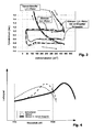
- FIG. 3 the pressure curve during a combustion cycle for a four-stroke gasoline engine is shown depending on the current cylinder volume for various engine operating methods in a pressure range up to 2 bar.
- the dotted line shows the pressure curve for a conventionally operated internal combustion engine with a displacement of 1.4 liters.
- the dashed line shows an engine with a (geometric) displacement of 1.6 liters in Atkinson plante, with the power of this engine corresponds approximately to that of the conventional 1.4-liter engine due to the reduced effective intake volume.
- the pressure curve of the Atkinson engine in the intake stroke (below) starts from a higher cylinder volume, with expansion work then being performed by another stroke during the power stroke (see graph in the diagram at the top right).
- the compression ratio is increased from about 11 for a conventional engine to 12.3 for the Atkinson engine.
- the actual values for the Atkinson cycle modified compression ratio will depend on various parameters, including the fuel used and the concomitant tendency to knock and the ratio between the effective intake volume and the expansion volume.
- an RON 91 fuel an increase in the compression ratio of typically 9.7 to about 10.8 is possible; with a RON 95 fuel from 11 to 12.3.
- the limit values for the compression ratios which can be used within the scope of the invention are approximately 13 to 14: 1. Compared to a comparable engine without Atkinson plante results in an increase in the geometric compression ratio of about 5% to 17%.
- FIG. 3 As can be seen, the effective intake volume due to the delayed intake valve closing in conventional engine and Atkinson engine is about the same, there are also comparable pumping losses at the throttle. These pumping losses can be reduced by carrying out a load control via a retardation of the intake valves. At a As a result, the throttling level at the throttle flap can be at least reduced, which reduces the pumping losses.
- a corresponding pressure trace curve for a 1.6 liter Atkinson engine with extended intake time is indicated by a solid line in FIG FIG. 3 shown.
- the intake curve for this engine is at a higher pressure level (ie a lower vacuum level); in the example at about 0.6 bar instead of 0.4 bar. As a result, the pumping losses are reduced. In the further course of the combustion cycle, the pressure curve behaves approximately like that of the Atkinson engine without load reduction.
- FIG. 4 is the degree of delivery, ie the ratio of actually admitted mixture volume to the total geometric volume, depending on the engine speed shown qualitatively for different engine types.
- a conventional engine with conventional intake manifold results in a dynamic superelevation with a maximum in the upper usable speed range.
- This effect is, as shown by the long dashed curve in FIG. 4 seen in an Atkinson engine with the same intake system significantly more pronounced, which is related to the overall shorter intake phases.
- the very strong increase in dynamic elevation leads to excessive air supply in the upper speed range, so that the pumping losses magnifying additional throttling is required to avoid engine knock.
- the maximum output level is expelled from the usable speed range, so that results in the usable speed range, a relatively flat course of delivery.
- FIG. 6 is a possible valve timing for a gasoline engine according to the invention shown qualitatively.
- the gasoline engine (not shown) has two camshafts for the intake and exhaust valves, the intake valves being variable in timing via a phase adjustment mechanism well known in the art.
- the phase adjustment is dependent on the respective driver requirements based on control signals of a microprocessor-controlled engine control, the control signals acting on corresponding actuators.
- a retardation of the intake timing for purposes of load control occurs.
- the inlet curve (IVO intake valve opening timing
- the illustrated displacement occurs, if a throttling of the engine is required, ie in the majority of all operating conditions including the idling mode.
- the intake valve timing corresponds approximately to the solid line.
- the engine controller calculates which load reduction is currently achievable through the intake valve timing.
- the additional required load reduction is then effected by adjusting an electronic throttle.
Landscapes
- Engineering & Computer Science (AREA)
- Chemical & Material Sciences (AREA)
- Combustion & Propulsion (AREA)
- Mechanical Engineering (AREA)
- General Engineering & Computer Science (AREA)
- Output Control And Ontrol Of Special Type Engine (AREA)
Description
Die vorliegende Erfindung betrifft einen Ottomotor mit variabler Ventilsteuerung und einem Betrieb im Atkinsonzyklus gemäß dem Oberbegriff des Patentanspruches 1.The present invention relates to a gasoline engine with variable valve timing and operation in the Atkinsonzyklus according to the preamble of claim 1.
Unter der Bezeichnung "Atkinsonzyklus" bzw. "Atkinsontakt" ist eine Steuerungstechnik für Ottomotoren bekannt, durch welche die Motoreffizienz gesteigert werden kann. Eine Definition und Analyse eines Otto-Atkinsontaktes, der ein variables Schließen der Einlaßventile und ein veränderliches Brennkammervolumen erfordert, findet sich bei
Weitere Ottomotoren, die im Atkinsonzyklus betrieben werden können, sind z.B. in der
Das Prinzip des Atkinsonzyklus in seiner einfachen Form wird nachfolgend anhand der
Die jeweils erste Zylinderdarstellung von links zeigt den Zylinder zum Zeitpunkt des Schließens der Einlaßventile. Ein wesentliches Merkmal des Atkinsonzyklus besteht darin, daß sich der Kolben zu diesem Zeitpunkt nicht am unteren Totpunkt (BDC) befindet, sondern bereits dahinter, so daß ein Teil des über das geöffnete Einlaßventil angesaugten Gemisches wieder in den Einlaßkanal zurück befördert wird. Dieses späte Schließen der Einlaßventile ermöglicht es, den Expansionszyklus (vgl. dritte Darstellung von links) über ein größeres Volumen durchzuführen, wodurch ein verbesserter thermodynamischer Wirkungsgrad erzielt wird. Hierdurch ist das effektive Verdichtungsverhältnis (d. h. das von dem Kolben verdrängte Volumen ab dem Schließzeitpunkt des Einlaßventils) gegenüber dem Expansionsverhältnis reduziert, wobei gleichzeitig der (maximale) Kompressionsdruck, der durch die Klopfneigung des verwendeten Kraftstoffes begrenzt ist, gegenüber einem konventionell betriebenen Motor im Wesentlichen beibehalten wird, vgl. die jeweils mittlere Darstellung in
Eine weitere grundsätzlich bekannte Maßnahme zur Erhöhung der Kraftstoffeffizienz ist der Einsatz einer variablen Nockenwellensteuerung. Bei der Nockenwellensteuerung handelt es sich um eine bekannte Technologie, die zunehmend bei Benzinmotoren mit doppelten oben liegenden Nockenwellen eingesetzt wird und mittlerweile auch im Kleinwagensegment wirtschaftlich einsetzbar ist.Another basically known measure for increasing fuel efficiency is the use of a variable camshaft control. The camshaft control is a well-known technology that is increasingly used in gasoline engines with double overhead camshafts and is now economically viable in the small car segment.
Mittels der variablen Nockenwellensteuerung wird u.a. versucht, die konventionelle Drosselklappen-Laststeuerung zu ersetzen, da diese relativ hohe Strömungsverluste (nachfolgend als "Pumpverluste" bezeichnet) mit sich bringt. Ein derartiger Betrieb eines Ottomotors ohne Drosselklappen kann beispielsweise über mechanische Ventilstellglieder mit einer hohen Flexibilität hinsichtlich der Öffnungs- und Schließzeitpunkte sowie des Ventilhubes erfolgen. Die Steuerung der Zylinderfüllung über den Ventilhub erfordert dabei jedoch eine große mechanische Präzision in der Ausführung, damit es bei kleinen Hüben nicht zu Ungleichheiten zwischen den verschiedenen Zylindern kommt. Diese Anforderungen verteuern die entsprechenden Systeme, verkomplizieren ihre Wartung und erhöhen die Störanfälligkeit.By means of the variable camshaft control inter alia, attempts to replace the conventional throttle load control, as this relatively high flow losses (hereinafter referred to as "pumping losses") brings with it. Such an operation of a gasoline engine without throttle valves can be done for example via mechanical valve actuators with a high flexibility with respect to the opening and closing times and the valve lift. The control of the cylinder filling However, over the valve stroke requires a great deal of mechanical precision in the design so that it does not come to inequalities between the different cylinders at small strokes. These requirements make the corresponding systems more expensive, complicate their maintenance and increase the susceptibility to interference.
Unter Kostenaspekten strebt man weiterhin an, Motorenfamilien mit Motoren unterschiedlicher Leistung zu konzipieren, die in Entwicklung, Herstellung und Wartung möglichst große Ähnlichkeiten aufweisen.In terms of costs, efforts continue to be made to design engine families with engines of different capacities, which have the greatest possible similarity in development, production and maintenance.
Vor diesem Hintergrund bestand eine Aufgabe der vorliegenden Erfindung darin, einen besonders kostengünstigen Ottomotor mit verbesserter Kraftstoffökonomie und vorteilhaften Drehmomenteigenschaften zu entwickeln, bei dessen Entwicklung auf ein leistungsstärkeres Mitglied einer Motorenfamilie zurückgegriffen werden kann.Against this background, an object of the present invention was to develop a particularly cost gasoline engine with improved fuel economy and advantageous torque characteristics, can be used in the development of a more powerful member of an engine family.
Die Lösung der vorgenannten Aufgabe erfolgt anhand der Merkmale des Patentanspruches 1.The solution of the aforementioned object is based on the features of claim 1.
Vorteilhafte Ausgestaltungen der Erfindung sind in den Unteransprüchen beschrieben.Advantageous embodiments of the invention are described in the subclaims.
Ein Merkmal der Erfindung, das auch unabhängig von den übrigen Merkmalen der Erfindung eingesetzt werden kann, besteht darin, daß der Verbrennungsmotor - vorzugsweise über seinen gesamten Betriebsbereich, d.h. Leerlauf, Teillast, Volllast - in einem Atkinsonzyklus betrieben wird. Hierzu ist die Einlaßventilsteuerung bevorzugt derart ausgebildet, daß das Schließen der Einlaßventile stets erst im Kompressionstakt jeweils deutlich nach dem unteren Totpunkt des Zylinderkolbens erfolgt. Dadurch, daß der Motor stets im Atkinsonbetrieb betrieben werden kann, kann dieser mit einem konstanten erhöhten geometrischen Kompressionsverhältnis betrieben werden, so daß aufwendige Einrichtungen, z. B. zur Kolbenhubverstellung, nicht erforderlich sind.A feature of the invention, which can also be used independently of the other features of the invention, is that the internal combustion engine - preferably over its entire operating range, ie idling, part load, full load - is operated in an Atkinson cycle. For this purpose, the intake valve control is preferably designed such that the closing of the intake valves always takes place only in the compression stroke in each case significantly after the bottom dead center of the cylinder piston. The fact that the engine can always be operated in Atkinsonbetrieb, this can be operated with a constant increased geometric compression ratio, so that expensive facilities, such. B. for piston stroke adjustment, are not required.
Ein weiteres Merkmal der Erfindung, das auch unabhängig von dem weiteren Merkmal der Erfindung eingesetzt werden kann, besteht darin, daß eine Laststeuerung durch eine Veränderung des Schließzeitpunktes der Einlaßventile erfolgt, wobei zur Verringerung der abgegebenen Last der Einlaßventilschließzeitpunkt nach spät verschoben wird bzw. zur Erhöhung der abgegebenen Last nach früh verschoben wird. Dabei verbleibt der Einlaßventilschließzeitpunkt in der Regel deutlich hinter dem unteren Totpunkt, so daß der Atkinsonzyklus aufrechterhalten bleibt. Durch die weitere Spätverstellung des Einlaßventilschließens wird ein zunehmend größerer Teil des eingelassenen Gemischs in den Ansaugkanal zurück befördert, so daß dieser Teil am Verbrennungsprozeß nicht teilnimmt. Die hierbei auftretenden Strömungsverluste sind - verglichen mit den Pumpverlusten an einer Drosselklappe - gering, so daß die Pumparbeit des Motors verringert wird.Another feature of the invention, which can also be used independently of the further feature of the invention, is that a load control by a change in the closing timing of the intake valves is carried out to reduce the output load, the intake valve closing timing is delayed or to increase the released load is moved to early. In this case, the intake valve closing timing usually remains well below the bottom dead center, so that the Atkinsonzyklus is maintained. As a result of the further retardation of the intake valve closure, an increasingly larger part of the introduced mixture is conveyed back into the intake passage, so that this part does not participate in the combustion process. The occurring flow losses are - compared to the pumping losses at a throttle valve - low, so that the pumping work of the engine is reduced.
Das Maß der hierdurch erzielbaren Laststeuerung reicht in der Regel nicht aus, um auf eine konventionelle Drosselklappe verzichten zu können, jedoch kann der Drosselungsgrad durch die Drosselklappe verringert werden, wodurch die Pumpverluste reduziert werden.The degree of load control achievable thereby is usually not sufficient to be able to do without a conventional throttle, but the degree of throttle can be reduced by the throttle valve, whereby the pumping losses are reduced.
In einer bevorzugten Ausführungsform der Erfindung liegt der Schließzeitpunkt des Einlaßventils in einem Bereich von 40 ° bis 160 °, bevorzugt in einem Bereich von mehr als 80 ° bis 130 ° Kurbelwellenwinkel hinter dem unteren Totpunkt der Kolbenbewegung.In a preferred embodiment of the invention, the closing time of the intake valve is in a range of 40 ° to 160 °, preferably in a range of more than 80 ° to 130 ° crankshaft angle behind the bottom dead center of the piston movement.
Die Verstellung des Einlaßventilschließzeitpunktes erfolgt bevorzugt mittels einer phasenverstellbaren Einlaßventilnockenwelle, d. h. einer Verstellung des Öffnungs- und Schließzeitpunktes sämtlicher Einlaßventile, wobei das Auslaßventil-timing in einer Ausführungsform der Erfindung jeweils unverändert bleibt. Das Auslaßventil-Timing kann alternativ im Hinblick auf einen optimierten Verbrennungsprozeß ebenfalls variiert werden; insbesondere ist eine gleichförmige Verstellung des Auslaßventiltimings mit dem Einlaßventiltiming möglich.The adjustment of the intake valve closing timing is preferably carried out by means of a phase-variable intake camshaft, d. H. an adjustment of the opening and closing timing of all the intake valves, wherein the exhaust valve timing remains unchanged in one embodiment of the invention. The exhaust valve timing may alternatively be varied in view of an optimized combustion process; In particular, a uniform adjustment of the exhaust valve timing with the intake valve timing is possible.
Im Rahmen der Erfindung sind auch andere Verstelleinrichtungen denkbar, so z. B. Verstellmechanismen, bei denen die Einlaßventilschließzeiteinstellung unabhängig von der Einlaßventilöffnungszeiteinstellung erfolgen kann. Es ist auch denkbar, daß die einzelnen Ventile mittels individueller Aktuatoren gesteuert werden, was eine maximale Steuerungsflexibilität gewährleistet. Die Erfindung kann auch bei Ottomotoren eingesetzt werden, die pro Zylinder jeweils mehrere Einlaß- und/oder Auslaßventile aufweisen.In the context of the invention, other adjustment are conceivable, such. B. Adjustment mechanisms in which the intake valve closing timing independently can be done from the intake valve opening timing. It is also conceivable that the individual valves are controlled by means of individual actuators, which ensures maximum control flexibility. The invention can also be used in gasoline engines, each having a plurality of intake and / or exhaust valves per cylinder.
Ein weiteres Merkmal der vorliegenden Erfindung, das auch unabhängig von den vorstehenden Merkmalen eingesetzt werden kann, besteht darin, daß das Ansaugsystem strömungsdynamisch derart dimensioniert ist, daß das drehzahlabhängige Maximum des Liefergrades, das als "dynamische Überhöhung" bezeichnet wird, erst bei einer Motordrehzahl erreicht wird, die oberhalb der Nenndrehzahl des Motors liegt, so daß diese dynamische Überhöhung nicht zum Tragen kommt.A further feature of the present invention, which can also be used independently of the above features, is that the intake system is fluid-dynamically dimensioned such that the speed-dependent maximum of the delivery level, which is referred to as "dynamic elevation", reached only at an engine speed is, which is above the rated speed of the engine, so that this dynamic cant does not come to fruition.
Dem liegen folgende Überlegungen zugrunde: Der Liefergrad, d.h. das Verhältnis der tatsächlich erreichten Zylinderfüllung bezogen auf die geometrisch mögliche Zylinderfüllung, verändert sich über den Drehzahlbereich des Motors und hat aufgrund von Resonanzeffekten ein lokales Maximum ("dynamische Überhöhung"). Die Ansaugsysteme konventioneller Motoren sind häufig so ausgelegt, daß die dynamische Überhöhung im oberen Drehzahlbereich liegt, um dort die Leistungs- und Drehmomententfaltung des Motors zu unterstützen. Im Rahmen der Erfindung hat es sich jedoch als zweckmäßig herausgestellt, das Ansaugsystem so auszulegen, daß die dynamische Überhöhung außerhalb des nutzbaren Drehzahlbereichs, d.h. oberhalb der Nenndrehzahl auftritt, typischerweise bei etwa 20% oberhalb der Nenndrehzahl oder bei Drehzahlen oberhalb von etwa 7000 U/min. Dadurch wird einer zu starken Füllung und damit einer zu hohen Verdichtung im oberen Drehzahlbereich entgegengewirkt und somit gewährleistet, daß der Verbrennungsprozeß auch in diesem Drehzahlbereich stets unterhalb der Klopfgrenze stattfinden kann. Dadurch werden - im Gegensatz zu konventionellen Motoren - Maßnahmen zur Verhinderung eines Klopfens - wie z. B. eine zusätzliche Drosselung - überflüssig, was wiederum die Kraftstoffökonomie verbessert.This is based on the following considerations: The degree of delivery, i. the ratio of the actually achieved cylinder filling with respect to the geometrically possible cylinder filling changes over the engine speed range and has a local maximum due to resonance effects ("dynamic overshoot"). The intake systems of conventional engines are often designed so that the dynamic increase in the upper speed range, there to assist the power and torque deployment of the engine. In the context of the invention, however, it has proven to be expedient to design the intake system so that the dynamic elevation outside the usable speed range, i. above the rated speed, typically at about 20% above rated speed or at speeds above about 7000 rpm. This counteracts excessive filling and thus too high compression in the upper speed range and thus ensures that the combustion process can always take place below the knock limit even in this speed range. This will - in contrast to conventional engines - measures to prevent knocking - such. As an additional throttling - superfluous, which in turn improves the fuel economy.
Die Drehzahl, bei der die dynamische Überhöhung auftritt, hängt, wie dem Fachmann allgemein bekannt ist, in relativ komplexer Weise von der Ansaugsystemgeometrie ab. Im Rahmen einer bevorzugten Ausführungsform der Erfindung wird vorgeschlagen, das Ansaugsystem in der Länge signifikant zu verkürzen, was in der Regel zu einem Anstieg der Drehzahl, bei der die dynamische Erhöhung auftritt, führt. Darüber hinaus sind im Rahmen der Erfindung auch andere Maßnahmen möglich, um die Resonanzeigenschaften des Ansaugsystems anzupassen, z.B. eine Veränderung des Durchmessers und/oder des Profils des Ansaugkanals.The speed at which the dynamic overshoot occurs depends, as is well known to those skilled in the art, on the intake system geometry in a relatively complex manner from. In a preferred embodiment of the invention, it is proposed to shorten the intake system significantly in length, which usually leads to an increase in the speed at which the dynamic increase occurs. In addition, other measures are possible within the scope of the invention to adapt the resonance characteristics of the intake system, for example a change in the diameter and / or the profile of the intake duct.
Die vorliegende Erfindung läßt sich besonders vorteilhaft im Rahmen eines Konzeptes für eine Motorenfamilie einsetzen, indem ein konventionell betriebener Motor mit vergleichsweise größerer Nennleistung und größerem Hubraum im Hinblick auf die Erfindung modifiziert wird, um so einen Motor mit geringerer Nennleistung zu erhalten. Hierzu sind lediglich relativ geringfügige Modifikationen erforderlich, so die Erhöhung des geometrischen Kompressionsverhältnisses, die Änderung der Hubkurve der Einlaßventile sowie der Ansauggeometrie. Ferner ist eine Verstellmöglichkeit wenigstens für den Einlaßventilschließzeitpunkt erforderlich. Der größere Hubraum des größeren Motorenfamilienmitgliedes wird für den vergrößerten Expansionstakt des Atkinsonzyklus genutzt, so daß die Zylindergeometrie gleich bleiben kann. Hierdurch werden mehrere Vorteile erzielt: Zum einen kann auf einheitliche Komponenten, insbesondere einen gleichen Motorblock für verschiedene Motormodelle zurückgegriffen werden. Da die Motoren einer Motorenfamilie im unteren und mittleren Leistungsbereich in der Regel gleiche äußere Abmessungen aufweisen, ist der größere geometrische Hubraum bei dem erfindungsgemäßen Motor hinsichtlich der Fertigungskosten nicht von Nachteil, da dieser aufgrund der größeren Hubraums größere Hohlräume enthält, und somit der Materialeinsatz nicht größer ist als bei einem Motor mit kleinerem Hubraum. Ferner arbeitet der erfindungsgemäße Motor aufgrund des Atkinsonbetriebs und der Einlaßventil-Laststeuerung besonders sparsam, was insbesondere im unteren Fahrzeugsegment von Bedeutung ist. Ferner hat sich herausgestellt, daß mit einem Motor gemäß der vorliegenden Erfindung ein im Vergleich zu konventionell im Atkinsonzyklus betriebenen Ottomotoren vergrößerter einsetzbarer Drehmoment/Lastbereich sowie ein vorteilhafter Volllast-Drehmomentverlauf erzielt werden kann.The present invention can be used to particular advantage in the context of a concept for an engine family by modifying a conventionally operated engine with comparatively larger rated power and larger displacement with respect to the invention so as to obtain a motor with lower nominal power. For this purpose, only relatively minor modifications are required, such as the increase of the geometric compression ratio, the change in the lift curve of the intake valves and the Ansauggeometrie. Furthermore, an adjustment is required at least for the intake valve closing timing. The larger displacement of the larger engine family member is used for the increased expansion stroke of the Atkinson cycle, so that the cylinder geometry can remain the same. As a result, several advantages are achieved: On the one hand can be used on uniform components, especially a same engine block for different engine models. Since the engines of an engine family in the lower and medium power range usually have the same outer dimensions, the larger geometric displacement in the engine according to the invention in terms of manufacturing costs is not a disadvantage, since this contains larger cavities due to the larger displacement, and thus the material usage is not greater is than with a smaller displacement engine. Furthermore, the engine according to the invention operates particularly sparingly due to the Atkinsonbetriebs and the intake valve load control, which is particularly important in the lower vehicle segment of importance. It has also been found that with an engine according to the present invention, an increased usable torque / load range as well as an advantageous full-load torque curve can be achieved in comparison to conventional gasoline engines operated in the Atkinson cycle.
Die vorliegende Erfindung wird bevorzugt bei einem Viertakt-Ottomotor eingesetzt, auf den sich auch die nachfolgende Beschreibung bezieht. Es ist darüber hinaus jedoch auch denkbar, das erfindungsgemäße Konzept bei einem Zweitakt-Ottomotor einzusetzen, sofern bei diesem geeignete Maßnahmen zur selektiven Steuerung des Gemischeinlasstimings zur Verfügung stehen.The present invention is preferably used in a four-stroke gasoline engine, to which the following description refers. However, it is also conceivable to use the inventive concept in a two-stroke gasoline engine, provided that suitable measures for the selective control of the mixture intake timing are available.
Neben dem Einsatz bei einem Vergaser-Verbrennungsmotor oder einem Motor mit Saugrohreinspritzung kann das erfindungsgemäße Konzept auch bei einem Motor mit Direkteinspritzung realisiert werden. In diesem Falle wird bei der verlängerten Einlaßphase des Atkinsonzyklus lediglich Ansaugluft in den Einlaßkanal zurückgeschoben.In addition to the use in a carburetor internal combustion engine or an engine with intake manifold injection, the inventive concept can also be realized in a direct injection engine. In this case, at the extended intake phase of the atkinsone cycle, only intake air is pushed back into the intake passage.
Im Folgenden wird die Erfindung anhand der Figuren beispielhaft näher erläutert. Es zeigen:
- Figur 1
- eine schematische Darstellung verschiedener Zylinderzustände eines konventionellen Verbrennungszyklus im Vergleich zu einem Atkinsonzyklus;
- Figur 2
- ein Druck/Zylindervolumendiagramm zur Erläuterung des Prinzips eines Atkinsonzyklus;
- Figur 3
- ein Zylinderdruck/Volumendiagramm mit einem Zylinderdruckverlauf für ein Motorbetriebsverfahren gemäß der Erfindung im Vergleich zu Druckverläufen für konventionelle Motorbetriebsverfahren;
- Figur 4
- ein Diagramm des drehzahlabhängigen Liefergradverlaufs für verschiedene Motorkonzepte;
- Figur 5
- ein Drehmoment/Drehzahl-Diagramm für einen erfindungsgemäßen Ottomotor, und
- Figur 6
- eine schematische Darstellung des Ventiltimings für einen erfindungsgemäßen Ottomotor.
- FIG. 1
- a schematic representation of various cylinder states of a conventional combustion cycle compared to an Atkinsonzyklus;
- FIG. 2
- a pressure / cylinder volume diagram for explaining the principle of an atkinsone cycle;
- FIG. 3
- a cylinder pressure / volume graph with a cylinder pressure curve for an engine operating method according to the invention in comparison with pressure curves for conventional engine operating methods;
- FIG. 4
- a diagram of the speed-dependent delivery degree course for different engine concepts;
- FIG. 5
- a torque / speed diagram for a gasoline engine according to the invention, and
- FIG. 6
- a schematic representation of the valve timing for a gasoline engine according to the invention.
In
Da, wie aus
In
Durch diese Maßnahmen wird, wie in
In
Claims (10)
- Spark ignition engine having an intake system and a plurality of cylinders with inlet and outlet valves respectively assigned to the cylinders, with a valve adjustment device by means of which at least the closing time of the inlet valves can be changed, the engine being designed for operation in the Atkinson cycle in which the inlet valves are closed after the bottom dead center of the piston movement in the compression stroke in such a way that the expansion ratio is increased with respect to the compression ratio, at least in specific engine operating parameter ranges load control being carried out by changing the closing time of the inlet valves, the inlet valve closing time being shifted in the retarded direction in order to reduce the load which is output, characterized in that the intake system is dimensioned in terms of flow dynamics in such a way that the rotational-speed-dependent maximum or the dynamic gain in the volumetric efficiency does not occur until an engine speed which is above the rated speed of the engine.
- Spark ignition engine according to Claim 1, characterized in that it is operated exclusively with the Atkinson cycle in the entire rotational speed/load range.
- Spark ignition engine according to Claim 1 or 2, characterized in that the variable closing time of the inlet valve lies in a range from 40° to 160°, preferably more than 80° to 130° crankshaft angle after the bottom dead center of the piston movement.
- Spark ignition engine according to at least one of Claims 1 to 3, characterized in that the intake system of the engine has a throttle valve, and in that the load control is carried out both by changing the inlet valve closing time and by changing the throttle valve position.
- Spark ignition engine according to Claim 4, characterized in that the load control is carried out as far as possible by changing the inlet valve closing time, and in that if the change in the inlet valve closing time is not sufficient to reach the predefined load, an additional load control is provided by the throttle valve.
- Spark ignition engine according to at least one of Claims 1 to 5, characterized in that the engine speed which is brought about by the dimensioning of the intake system and at which the dynamic gain occurs lies in a rotational speed range from 5% to 50% above the rated speed of the engine, preferably at approximately 20% above the rated speed or preferably above an engine speed of approximately 7000 rpm.
- Spark ignition engine according to at least one of Claims 1 to 6, characterized in that the intake system is embodied with a shortened length compared to an intake system of a comparable conventional spark ignition engine in which the rotational speed at which the dynamic gain occurs is below the rated speed.
- Spark ignition engine according to at least one of Claims 1 to 7, characterized in that the geometric compression ratio of the engine has a value between approximately 9:1 to approximately 14:1, or in that the geometric compression ratio is increased by approximately 5% to approximately 17% compared to a comparable engine without the Atkinson operating mode.
- Spark ignition engine according to at least one of Claims 1 to 8, characterized in that said engine has a camshaft which is assigned in each case to the inlet valves and a camshaft which is assigned in each case to the outlet valves, the camshaft which is assigned to the inlet valves having an adjustment element for the purpose of selective angular adjustment compared to the crankshaft of the engine, and in that the camshaft which is assigned to the outlet valves either has invariable timing or is also of adjustable design, the adjustment preferably being carried out in accordance with the inlet valve adjustment.
- Spark ignition engine according to at least one of Claims 2 to 9, characterized in that the latter is a component of an engine family of engines with different cubic capacities, and the spark ignition engine corresponds in design terms essentially to an engine model of the engine family with a relatively large cubic capacity, the model with a relatively large cubic capacity not being designed for operating with the Atkinson cycle.
Priority Applications (2)
| Application Number | Priority Date | Filing Date | Title |
|---|---|---|---|
| DE502005003109T DE502005003109D1 (en) | 2005-08-17 | 2005-08-17 | Gasoline engine with variable valve timing and operation in the Atkinson cycle |
| EP05107545A EP1754872B1 (en) | 2005-08-17 | 2005-08-17 | Otto engine with variable valve actuation and Atkinson cycle operation |
Applications Claiming Priority (1)
| Application Number | Priority Date | Filing Date | Title |
|---|---|---|---|
| EP05107545A EP1754872B1 (en) | 2005-08-17 | 2005-08-17 | Otto engine with variable valve actuation and Atkinson cycle operation |
Publications (2)
| Publication Number | Publication Date |
|---|---|
| EP1754872A1 EP1754872A1 (en) | 2007-02-21 |
| EP1754872B1 true EP1754872B1 (en) | 2008-03-05 |
Family
ID=35502482
Family Applications (1)
| Application Number | Title | Priority Date | Filing Date |
|---|---|---|---|
| EP05107545A Not-in-force EP1754872B1 (en) | 2005-08-17 | 2005-08-17 | Otto engine with variable valve actuation and Atkinson cycle operation |
Country Status (2)
| Country | Link |
|---|---|
| EP (1) | EP1754872B1 (en) |
| DE (1) | DE502005003109D1 (en) |
Cited By (5)
| Publication number | Priority date | Publication date | Assignee | Title |
|---|---|---|---|---|
| DE102008036494A1 (en) * | 2008-08-05 | 2010-02-11 | Mahle International Gmbh | Stationary loaded four-stroke internal-combustion engine i.e. diesel engine, operating method for commercial motor vehicle, involves actuating auxiliary valves during operation of engine such that auxiliary valves close paths |
| DE102008064538A1 (en) | 2008-12-19 | 2010-06-24 | Dr. Ing. H.C. F. Porsche Aktiengesellschaft | Hybrid vehicle operating method, involves extending characteristic range of internal-combustion engine by hybrid drive, where characteristic range is assigned to consumption-favorable operating mode |
| DE102013003682A1 (en) | 2013-02-27 | 2014-08-28 | Victor Gheorghiu | Internal combustion engine working after the real four-stroke Atkinson cycle and procedures to their load control |
| CN104343548A (en) * | 2013-08-09 | 2015-02-11 | 爱信精机株式会社 | Engine control mechanism |
| DE102014201712A1 (en) | 2014-01-31 | 2015-08-06 | Schaeffler Technologies AG & Co. KG | Camshaft adjusting device for an internal combustion engine |
Families Citing this family (6)
| Publication number | Priority date | Publication date | Assignee | Title |
|---|---|---|---|---|
| US7765806B2 (en) * | 2006-08-21 | 2010-08-03 | Gm Global Technology Operations, Inc. | Atkinson cycle powertrain |
| DE102006042912A1 (en) * | 2006-09-13 | 2008-03-27 | Volkswagen Ag | Internal combustion engine with mixed camshafts |
| US8150597B2 (en) | 2008-02-26 | 2012-04-03 | Mazda Motor Corporation | Method and system for controlling an internal combustion engine |
| RU2442902C2 (en) * | 2010-05-17 | 2012-02-20 | Герман Николаевич Ерченко | Highly economical means of internal combustion engine operation according to erchenko cycle |
| US8794200B2 (en) * | 2012-11-21 | 2014-08-05 | GM Global Technology Operations LLC | Engine assembly with phasing mechanism on eccentric shaft for variable cycle engine |
| RU2586032C1 (en) * | 2015-02-17 | 2016-06-10 | Виктор Семенович Савченков | Method of operating internal combustion engine with compression ignition |
Family Cites Families (2)
| Publication number | Priority date | Publication date | Assignee | Title |
|---|---|---|---|---|
| DE50206880D1 (en) * | 2002-02-21 | 2006-06-29 | Ford Global Tech Llc | Four-stroke gasoline engine with camshaft adjustment |
| DE50212655D1 (en) * | 2002-03-08 | 2008-09-25 | Ford Global Tech Llc | Method for controlling a four-stroke gasoline engine with variable valve timing |
-
2005
- 2005-08-17 EP EP05107545A patent/EP1754872B1/en not_active Not-in-force
- 2005-08-17 DE DE502005003109T patent/DE502005003109D1/en active Active
Cited By (6)
| Publication number | Priority date | Publication date | Assignee | Title |
|---|---|---|---|---|
| DE102008036494A1 (en) * | 2008-08-05 | 2010-02-11 | Mahle International Gmbh | Stationary loaded four-stroke internal-combustion engine i.e. diesel engine, operating method for commercial motor vehicle, involves actuating auxiliary valves during operation of engine such that auxiliary valves close paths |
| DE102008064538A1 (en) | 2008-12-19 | 2010-06-24 | Dr. Ing. H.C. F. Porsche Aktiengesellschaft | Hybrid vehicle operating method, involves extending characteristic range of internal-combustion engine by hybrid drive, where characteristic range is assigned to consumption-favorable operating mode |
| DE102013003682A1 (en) | 2013-02-27 | 2014-08-28 | Victor Gheorghiu | Internal combustion engine working after the real four-stroke Atkinson cycle and procedures to their load control |
| DE102013003682B4 (en) | 2013-02-27 | 2018-03-15 | Victor Gheorghiu | Method for load control and cylinder deactivation of an internal combustion engine operating after the real four-stroke Atkinson cycle |
| CN104343548A (en) * | 2013-08-09 | 2015-02-11 | 爱信精机株式会社 | Engine control mechanism |
| DE102014201712A1 (en) | 2014-01-31 | 2015-08-06 | Schaeffler Technologies AG & Co. KG | Camshaft adjusting device for an internal combustion engine |
Also Published As
| Publication number | Publication date |
|---|---|
| EP1754872A1 (en) | 2007-02-21 |
| DE502005003109D1 (en) | 2008-04-17 |
Similar Documents
| Publication | Publication Date | Title |
|---|---|---|
| DE69600937T2 (en) | Adjustment of the camshaft phase for cylinder deactivation | |
| DE69703511T2 (en) | Internal combustion engine with adjustable valve drive | |
| DE10359267B4 (en) | Internal combustion engine with intake valves, variable valve timing and timing | |
| DE102016209957A1 (en) | Method for operating an internal combustion engine and internal combustion engine | |
| DE102017206266A1 (en) | Method for operating an internal combustion engine and internal combustion engine | |
| EP1754872B1 (en) | Otto engine with variable valve actuation and Atkinson cycle operation | |
| EP1331382B1 (en) | Method, computer programme, control and/or regulation device for operation of an internal combustion engine and internal combustion engine | |
| WO2017102042A1 (en) | Method for operating a reciprocating internal combustion engine | |
| WO2005035958A1 (en) | Method for optimizing the operation of a charged reciprocating internal combustion engine in the lower engine speed range | |
| EP1338777A1 (en) | Four stroke engine with a camshaft phasing device | |
| EP1338776B1 (en) | Four stroke spark ignition engine with separate variable camshafts and method therefor | |
| DE102008036494A1 (en) | Stationary loaded four-stroke internal-combustion engine i.e. diesel engine, operating method for commercial motor vehicle, involves actuating auxiliary valves during operation of engine such that auxiliary valves close paths | |
| DE102006014965A1 (en) | Diesel engine has camshafts whose cams can be adjusted to control operating time of charge cycle valves, each cam being made up of two sections which swivel with respect to each other, each section controlling valve on single cylinder | |
| DE102010042762A1 (en) | Combustion engine e.g. diesel engine, for motor car, has pressure piston lying at rotary cam that sits on cam shaft, where cam shaft has phase adjustor for adjusting phase position of cam shaft with respect to crankshaft | |
| WO2013143687A1 (en) | Method for operating an internal combustion engine | |
| DE102021005647A1 (en) | Method for operating an internal combustion engine, in particular a motor vehicle | |
| DE102016117556A1 (en) | Method for operating a drive system and drive system | |
| DE102020006622A1 (en) | Method for operating an internal combustion engine, in particular a motor vehicle | |
| DE102019007444A1 (en) | Internal combustion engine for a motor vehicle and a method for operating such an internal combustion engine | |
| DE102019005128A1 (en) | Method for operating an internal combustion engine of a motor vehicle, in particular a motor vehicle | |
| WO2018192821A1 (en) | Method for operating an internal combustion engine, in particular of a motor vehicle | |
| DE202015106072U1 (en) | Internal combustion engine with variable valve train | |
| WO2018114019A1 (en) | Method for operating a reciprocating piston internal combustion engine | |
| DE102015219414A1 (en) | Internal combustion engine with variable valve train and method for operating such an internal combustion engine | |
| DE102022212010A1 (en) | Overrun of a combustion engine |
Legal Events
| Date | Code | Title | Description |
|---|---|---|---|
| PUAI | Public reference made under article 153(3) epc to a published international application that has entered the european phase |
Free format text: ORIGINAL CODE: 0009012 |
|
| AK | Designated contracting states |
Kind code of ref document: A1 Designated state(s): AT BE BG CH CY CZ DE DK EE ES FI FR GB GR HU IE IS IT LI LT LU LV MC NL PL PT RO SE SI SK TR |
|
| AX | Request for extension of the european patent |
Extension state: AL BA HR MK YU |
|
| 17P | Request for examination filed |
Effective date: 20070821 |
|
| AKX | Designation fees paid |
Designated state(s): DE FR GB |
|
| GRAP | Despatch of communication of intention to grant a patent |
Free format text: ORIGINAL CODE: EPIDOSNIGR1 |
|
| GRAS | Grant fee paid |
Free format text: ORIGINAL CODE: EPIDOSNIGR3 |
|
| GRAA | (expected) grant |
Free format text: ORIGINAL CODE: 0009210 |
|
| AK | Designated contracting states |
Kind code of ref document: B1 Designated state(s): DE FR GB |
|
| REG | Reference to a national code |
Ref country code: GB Ref legal event code: FG4D Free format text: NOT ENGLISH |
|
| REF | Corresponds to: |
Ref document number: 502005003109 Country of ref document: DE Date of ref document: 20080417 Kind code of ref document: P |
|
| ET | Fr: translation filed | ||
| PLBE | No opposition filed within time limit |
Free format text: ORIGINAL CODE: 0009261 |
|
| STAA | Information on the status of an ep patent application or granted ep patent |
Free format text: STATUS: NO OPPOSITION FILED WITHIN TIME LIMIT |
|
| 26N | No opposition filed |
Effective date: 20081208 |
|
| REG | Reference to a national code |
Ref country code: FR Ref legal event code: PLFP Year of fee payment: 11 |
|
| REG | Reference to a national code |
Ref country code: FR Ref legal event code: PLFP Year of fee payment: 12 |
|
| REG | Reference to a national code |
Ref country code: FR Ref legal event code: PLFP Year of fee payment: 13 |
|
| REG | Reference to a national code |
Ref country code: FR Ref legal event code: PLFP Year of fee payment: 14 |
|
| PGFP | Annual fee paid to national office [announced via postgrant information from national office to epo] |
Ref country code: FR Payment date: 20190717 Year of fee payment: 15 |
|
| PGFP | Annual fee paid to national office [announced via postgrant information from national office to epo] |
Ref country code: GB Payment date: 20190728 Year of fee payment: 15 |
|
| GBPC | Gb: european patent ceased through non-payment of renewal fee |
Effective date: 20200817 |
|
| PG25 | Lapsed in a contracting state [announced via postgrant information from national office to epo] |
Ref country code: FR Free format text: LAPSE BECAUSE OF NON-PAYMENT OF DUE FEES Effective date: 20200831 |
|
| PG25 | Lapsed in a contracting state [announced via postgrant information from national office to epo] |
Ref country code: GB Free format text: LAPSE BECAUSE OF NON-PAYMENT OF DUE FEES Effective date: 20200817 |
|
| PGFP | Annual fee paid to national office [announced via postgrant information from national office to epo] |
Ref country code: DE Payment date: 20220615 Year of fee payment: 18 |
|
| P01 | Opt-out of the competence of the unified patent court (upc) registered |
Effective date: 20230620 |
|
| REG | Reference to a national code |
Ref country code: DE Ref legal event code: R119 Ref document number: 502005003109 Country of ref document: DE |
|
| PG25 | Lapsed in a contracting state [announced via postgrant information from national office to epo] |
Ref country code: DE Free format text: LAPSE BECAUSE OF NON-PAYMENT OF DUE FEES Effective date: 20240301 |