EP0225508A2 - Radial roller bearing cage for cylindrical rollers - Google Patents
Radial roller bearing cage for cylindrical rollers Download PDFInfo
- Publication number
- EP0225508A2 EP0225508A2 EP86115889A EP86115889A EP0225508A2 EP 0225508 A2 EP0225508 A2 EP 0225508A2 EP 86115889 A EP86115889 A EP 86115889A EP 86115889 A EP86115889 A EP 86115889A EP 0225508 A2 EP0225508 A2 EP 0225508A2
- Authority
- EP
- European Patent Office
- Prior art keywords
- webs
- roller bearing
- cage
- bearing cage
- Prior art date
- Legal status (The legal status is an assumption and is not a legal conclusion. Google has not performed a legal analysis and makes no representation as to the accuracy of the status listed.)
- Granted
Links
- 238000005096 rolling process Methods 0.000 claims abstract description 21
- 238000003466 welding Methods 0.000 description 2
- 210000001061 forehead Anatomy 0.000 description 1
- 238000004519 manufacturing process Methods 0.000 description 1
Images
Classifications
-
- F—MECHANICAL ENGINEERING; LIGHTING; HEATING; WEAPONS; BLASTING
- F16—ENGINEERING ELEMENTS AND UNITS; GENERAL MEASURES FOR PRODUCING AND MAINTAINING EFFECTIVE FUNCTIONING OF MACHINES OR INSTALLATIONS; THERMAL INSULATION IN GENERAL
- F16C—SHAFTS; FLEXIBLE SHAFTS; ELEMENTS OR CRANKSHAFT MECHANISMS; ROTARY BODIES OTHER THAN GEARING ELEMENTS; BEARINGS
- F16C33/00—Parts of bearings; Special methods for making bearings or parts thereof
- F16C33/30—Parts of ball or roller bearings
- F16C33/46—Cages for rollers or needles
- F16C33/54—Cages for rollers or needles made from wire, strips, or sheet metal
- F16C33/542—Cages for rollers or needles made from wire, strips, or sheet metal made from sheet metal
- F16C33/543—Cages for rollers or needles made from wire, strips, or sheet metal made from sheet metal from a single part
-
- F—MECHANICAL ENGINEERING; LIGHTING; HEATING; WEAPONS; BLASTING
- F16—ENGINEERING ELEMENTS AND UNITS; GENERAL MEASURES FOR PRODUCING AND MAINTAINING EFFECTIVE FUNCTIONING OF MACHINES OR INSTALLATIONS; THERMAL INSULATION IN GENERAL
- F16C—SHAFTS; FLEXIBLE SHAFTS; ELEMENTS OR CRANKSHAFT MECHANISMS; ROTARY BODIES OTHER THAN GEARING ELEMENTS; BEARINGS
- F16C33/00—Parts of bearings; Special methods for making bearings or parts thereof
- F16C33/30—Parts of ball or roller bearings
- F16C33/46—Cages for rollers or needles
- F16C33/54—Cages for rollers or needles made from wire, strips, or sheet metal
- F16C33/541—Details of individual pockets, e.g. shape or roller retaining means
-
- F—MECHANICAL ENGINEERING; LIGHTING; HEATING; WEAPONS; BLASTING
- F16—ENGINEERING ELEMENTS AND UNITS; GENERAL MEASURES FOR PRODUCING AND MAINTAINING EFFECTIVE FUNCTIONING OF MACHINES OR INSTALLATIONS; THERMAL INSULATION IN GENERAL
- F16C—SHAFTS; FLEXIBLE SHAFTS; ELEMENTS OR CRANKSHAFT MECHANISMS; ROTARY BODIES OTHER THAN GEARING ELEMENTS; BEARINGS
- F16C19/00—Bearings with rolling contact, for exclusively rotary movement
- F16C19/22—Bearings with rolling contact, for exclusively rotary movement with bearing rollers essentially of the same size in one or more circular rows, e.g. needle bearings
- F16C19/24—Bearings with rolling contact, for exclusively rotary movement with bearing rollers essentially of the same size in one or more circular rows, e.g. needle bearings for radial load mainly
- F16C19/26—Bearings with rolling contact, for exclusively rotary movement with bearing rollers essentially of the same size in one or more circular rows, e.g. needle bearings for radial load mainly with a single row of rollers
Definitions
- the invention relates to a radial roller bearing cage for cylindrical rolling elements, consisting of two end rings lying in mutually parallel planes, which are connected to one another by axially extending webs distributed over the circumference, so that between these webs there are pockets for accommodating two rolling elements arranged one behind the other in the circumferential direction are formed, and the webs have holding projections projecting into the pockets near their inner and outer boundary edges, the cage being rolled up from a flat band and welded to the end rings in the region of a pocket.
- the invention has for its object to solve the problem of the rolling element holder in the pocket in which the weld is located with simple design means.
- the invention solves this problem in a simple manner in that the pocket within which the joint lies is dimensioned such that it only accommodates a single rolling element. However, it is possible to hold a single rolling element in this pocket even with very considerable width tolerances.
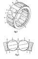
- the cage shown in Figure 1 which is rolled from a flat band, consists of the two end rings 1, which are connected by axially extending webs 2. Forehead rings and webs limit pockets 3, which each serve to hold two cylindrical rolling elements 4.
- Figure 2 shows in a cross section the arrangement of the two rolling elements 4 in a pocket 3, and it shows in particular that 2 retaining projections 5 are provided on the webs, which protrude into the pocket 3 and thereby the rolling elements 4 against falling out in both radial directions hold.
- the joint 6 can be seen at which the two cage ends meet after welding and are welded.
- This joint 6 lies in the area of a pocket 7, in which only a single rolling element 4 is accommodated.
Landscapes
- Engineering & Computer Science (AREA)
- General Engineering & Computer Science (AREA)
- Mechanical Engineering (AREA)
- Rolling Contact Bearings (AREA)
Abstract
Bei einem Radial-Wälzlagerkäfig für zylindrische Wälzkörper (4), der Taschen (3) aufweist, in denen jeweils zwei in Umfangsrichtung hintereinander angeordnete Wälzkörper (4) untergebracht sind, die durch von den Käfigstegen ausgehenden und in die Taschen (3) ragende Haltevorsprünge (5) gehalten sind, wobei der Käfig aus einem flachen Band rundgerollt und an der im Bereich einer Tasche liegenden Stoßstelle (6) an den Stirnringen (1) verschweißt ist, wird zum Zwecke der sicheren Wälzkörperhalterung in dieser letztgenannten Tasche diese Tasche (7) so dimensioniert, daß sie nur einen einzigen Wälzkörper (4) aufnimmt.In the case of a radial roller bearing cage for cylindrical roller bodies (4), which has pockets (3), in each of which two roller bodies (4) arranged one behind the other in the circumferential direction are accommodated. 5) are held, the cage being rolled out of a flat band and welded to the end rings (1) at the joint (6) in the area of a pocket, this pocket (7) is so in this latter pocket for the purpose of secure rolling element mounting dimensioned that it receives only a single rolling element (4).
Description
Die Erfindung betrifft einen Radial-Wälzlagerkäfig für zylindrische Wälzkörper, bestehend aus zwei in zueinander parallelen Ebenen liegenden Stirnringen, die durch über den Umfang verteilte axial verlaufende Stege miteinander verbunden sind, wodurch zwischen diesen Stegen Taschen für die Aufnahme von je zwei in Umfangsrichtung hintereinander angeordneten Wälzkörpern gebildet sind, und die Stege in der Nähe ihrer inneren und äußeren Begrenzungskanten in die Taschen ragende Haltevorsprünge aufweisen, wobei der Käfig aus einem flachen Band rundgerollt und an der im Bereich einer Tasche liegenden Stoßstelle an den Stirnringen verschweißt ist.The invention relates to a radial roller bearing cage for cylindrical rolling elements, consisting of two end rings lying in mutually parallel planes, which are connected to one another by axially extending webs distributed over the circumference, so that between these webs there are pockets for accommodating two rolling elements arranged one behind the other in the circumferential direction are formed, and the webs have holding projections projecting into the pockets near their inner and outer boundary edges, the cage being rolled up from a flat band and welded to the end rings in the region of a pocket.
Derartige Käfige, bei denen in einer gemeinsamen Tasche zwei Wälzkörper hintereinander laufen, sind seit langer Zeit bekannt. Wenn bei diesen Käfigen die Halterung der Wälzkörper durch Haltevorsprünge bewirkt werden soll, die von den Stegen ausgehend in die Tasche ragen, dann müssen für die Taschenbreite ganz enge Toleranzen eingehalten werden. Wenn dies nicht möglich ist, müssen erheblich aufwendigere Haltemaßnahmen ergriffen werden, wie z. B. von den Stirnringen ausgehende axiale Vorsprünge, die in stirnseitige Ausnehmungen der Wälzkörper eingreifen (DE-OS 27 12 834).Such cages, in which two rolling elements run one behind the other in a common pocket, have been known for a long time. If, in these cages, the rolling elements are to be held by holding projections which protrude from the webs into the pocket, then very narrow tolerances must be observed for the pocket width. If this is not possible, much more complex holding measures must be taken, such as. B. starting from the end rings axial projections which engage in end recesses of the rolling elements (DE-OS 27 12 834).
Mit modernen Fertigungsverfahren ist es jedoch durchaus möglich, die Toleranzen einzuhalten, die erforderlich sind, wenn die Wälzkörperhalterung durch von den Stegen ausgehende Haltevorsprünge bewirkt werden soll. Bei den Käfigen, die aus einem flachen Band rundgerollt werden und deren Stoßstelle, an der die Käfigenden miteinander verschweißt werden, im Bereich einer Tasche liegt, können jedoch in dieser Tasche bedingt durch die Schweißung Breitentoleranzen auftreten, die eine sichere Halterung der Wälzkörper nicht mehr gewährleisten.With modern manufacturing processes, however, it is quite possible to meet the tolerances that are required when the rolling element holds tion should be brought about by holding projections extending from the webs. In the case of the cages, which are rolled out of a flat band and whose joint at which the cage ends are welded together, is in the area of a pocket, width tolerances can occur in this pocket due to the welding, which no longer guarantee that the rolling elements are held securely .
Der Erfindung liegt die Aufgabe zugrunde, das Problem der Wälzkörperhalterung in der Tasche, in der die Schweißstelle liegt, mit einfachen konstruktiven Mitteln zu lösen.The invention has for its object to solve the problem of the rolling element holder in the pocket in which the weld is located with simple design means.
Diese Aufgabe löst die Erfindung in einfacher Weise dadurch, daß die Tasche, innerhalb der die Stoßstelle liegt, so dimensioniert ist, daß sie nur einen einzigen Wälzkörper aufnimmt. Die Halterung eines einzigen Wälzkörpers ist jedoch auch bei ganz erheblichen Breitentoleranzen in dieser Tasche sicher möglich.The invention solves this problem in a simple manner in that the pocket within which the joint lies is dimensioned such that it only accommodates a single rolling element. However, it is possible to hold a single rolling element in this pocket even with very considerable width tolerances.
In den Zeichnungen ist die Erfindung in einem Ausführungsbeispiel dargestellt. Es zeigt:
- Fig. 1 einen erfindungsgemäßen Käfig in perspektivischer Darstellung und
- Fig. 2 einen Querschnitt durch eine Wälzkörpertasche mit zwei Wälzkörpern.
- Fig. 1 shows a cage according to the invention in perspective and
- Fig. 2 shows a cross section through a rolling element pocket with two rolling elements.
Der in Figur 1 dargestellte Käfig, der aus einem flachen Band rundgerollt ist, besteht aus den beiden Stirnringen 1, die durch axial verlaufende Stege 2 miteinander verbunden sind. Stirnringe und Stege begrenzen dabei Taschen 3, die jeweils für die Aufnahme von zwei zylindrischen Wälzkörpern 4 dienen.The cage shown in Figure 1, which is rolled from a flat band, consists of the two
Figur 2 zeigt in einem Querschnitt die Anordnung der beiden Wälzkörper 4 in einer Tasche 3, und sie läßt insbesondere erkennen, daß an den Stegen 2 Haltevorsprünge 5 vorgesehen sind, die in die Tasche 3 hineinragen und dabei die Wälzkörper 4 gegen Herausfallen in beiden radialen Richtungen halten.Figure 2 shows in a cross section the arrangement of the two rolling elements 4 in a
In Figur 1 ist die Stoßstelle 6 zu erkennen, an der nach dem Rundbiegen die beiden Käfigenden aufeinandertreffen und verschweißt werden. Diese Stoßstelle 6 liegt im Bereich einer Tasche 7, in welcher nur ein einziger Wälzkörper 4 untergebracht ist.In FIG. 1, the joint 6 can be seen at which the two cage ends meet after welding and are welded. This joint 6 lies in the area of a
Claims (1)
Applications Claiming Priority (2)
| Application Number | Priority Date | Filing Date | Title |
|---|---|---|---|
| DE3543364 | 1985-12-07 | ||
| DE19853543364 DE3543364A1 (en) | 1985-12-07 | 1985-12-07 | RADIAL ROLLER BEARING CAGE FOR CYLINDRICAL ROLLER BODIES |
Publications (3)
| Publication Number | Publication Date |
|---|---|
| EP0225508A2 true EP0225508A2 (en) | 1987-06-16 |
| EP0225508A3 EP0225508A3 (en) | 1987-10-14 |
| EP0225508B1 EP0225508B1 (en) | 1989-09-06 |
Family
ID=6287944
Family Applications (1)
| Application Number | Title | Priority Date | Filing Date |
|---|---|---|---|
| EP86115889A Expired EP0225508B1 (en) | 1985-12-07 | 1986-11-15 | Radial roller bearing cage for cylindrical rollers |
Country Status (5)
| Country | Link |
|---|---|
| US (1) | US4952079A (en) |
| EP (1) | EP0225508B1 (en) |
| JP (1) | JPS62137415A (en) |
| DE (2) | DE3543364A1 (en) |
| ES (1) | ES2010656B3 (en) |
Families Citing this family (22)
| Publication number | Priority date | Publication date | Assignee | Title |
|---|---|---|---|---|
| DE8916005U1 (en) * | 1989-11-02 | 1992-09-24 | SKF GmbH, 8720 Schweinfurt | Rolling bearing cage |
| DE4142433C1 (en) * | 1991-12-20 | 1993-05-27 | Ibo Gesellschaft Fuer Beschaffung Und Absatz Von Industrieguetern Mbh, 8011 Kirchheim, De | Combined roller and ball bearing with inner and outer races - is of thin race type with rollers and balls of same dia. and on same race tracks |
| JPH07127646A (en) * | 1993-10-29 | 1995-05-16 | Ntn Corp | Retainer for roller bearing |
| JP3665653B2 (en) * | 1993-11-30 | 2005-06-29 | Ntn株式会社 | Roller bearing cage and manufacturing method thereof |
| US5413416A (en) * | 1993-12-03 | 1995-05-09 | Rexnord Corporation | Roller guide member for full complement roller bearing |
| JPH08270658A (en) * | 1995-01-30 | 1996-10-15 | Koyo Seiko Co Ltd | Cage for needle-form roller bearing and needle-form roller bearing |
| DE19531905B4 (en) * | 1995-08-30 | 2004-11-18 | Skf Gmbh | Plastic cage with on-board or running track |
| DE19612307A1 (en) * | 1996-03-28 | 1997-10-02 | Schaeffler Waelzlager Kg | Radial roller bearings |
| US6883970B2 (en) | 1999-12-16 | 2005-04-26 | 598992 Saskatchewan Ltd. | Thrust bearing |
| DE10326418A1 (en) * | 2002-07-02 | 2004-01-22 | Ina-Schaeffler Kg | Needle cage comprises rings connected by strips which have central sections raised above end sections and connected to them by sloping sections |
| US6666585B1 (en) | 2002-07-19 | 2003-12-23 | The Timken Company | Unitized cage for cylindrical roller bearing |
| JP2007010026A (en) * | 2005-06-30 | 2007-01-18 | Ntn Corp | Cylindrical roller bearing and its cage |
| DE102007011244A1 (en) * | 2007-03-08 | 2008-09-18 | Oerlikon Leybold Vacuum Gmbh | Roller bearing for storage of fast-rotating component in turbo-molecular pump, has retaining chambers for retaining roller body, where distance between adjacent retaining chambers differs from remaining distance between retaining chambers |
| JP2011196421A (en) * | 2010-03-18 | 2011-10-06 | Ntn Corp | Needle-like roller with retainer |
| DE102010013629B4 (en) | 2010-04-01 | 2012-04-19 | Aktiebolaget Skf | needle roller bearings |
| JP5805184B2 (en) * | 2011-05-24 | 2015-11-04 | 株式会社ハーモニック・ドライブ・システムズ | Roller bearing cage and needle roller bearing |
| JP5953699B2 (en) * | 2011-10-17 | 2016-07-20 | 日本精工株式会社 | Radial roller bearing cage |
| EP2815142A4 (en) * | 2012-02-14 | 2016-01-06 | Skf Ab | Method, cage and rolling bearing |
| US9033587B1 (en) | 2013-01-29 | 2015-05-19 | Roller Bearing Company Of America, Inc. | Cage for a roller bearing and a method of manufacturing the same |
| JP6657555B2 (en) * | 2014-08-01 | 2020-03-04 | 株式会社ジェイテクト | Roller bearing |
| JP2017166591A (en) * | 2016-03-16 | 2017-09-21 | Ntn株式会社 | Cage for oscillation bearing and oscillation bearing with this cage |
| JP7360260B2 (en) * | 2019-06-28 | 2023-10-12 | ナブテスコ株式会社 | Decelerator |
Citations (5)
| Publication number | Priority date | Publication date | Assignee | Title |
|---|---|---|---|---|
| US2772128A (en) * | 1953-06-13 | 1956-11-27 | Ind Schaeffier | Cage for needle bearings |
| US3353246A (en) * | 1965-07-01 | 1967-11-21 | Orange Roller Bearing Company | Method of making a cage for a roller bearing |
| FR1513488A (en) * | 1967-01-03 | 1968-02-16 | Nadella | Rolled and welded bearing cage |
| FR2233524A1 (en) * | 1973-06-14 | 1975-01-10 | Schaeffler Ohg Industriewerk | |
| DE2712834A1 (en) * | 1976-03-25 | 1977-10-06 | Torrington Co | ARRANGEMENT OF STORAGE CAGE AND ROLLERS AND METHOD FOR MAKING THIS ARRANGEMENT |
Family Cites Families (3)
| Publication number | Priority date | Publication date | Assignee | Title |
|---|---|---|---|---|
| FR1470088A (en) * | 1967-04-21 | 1967-02-17 | Torrington Mfg Co | Manufacturing process for bearing cages |
| FR2149621A5 (en) * | 1971-08-17 | 1973-03-30 | Pitner Alfred | |
| US3992764A (en) * | 1975-09-22 | 1976-11-23 | The Torrington Company | Method of forming a roller cage |
-
1985
- 1985-12-07 DE DE19853543364 patent/DE3543364A1/en not_active Withdrawn
-
1986
- 1986-11-15 DE DE8686115889T patent/DE3665495D1/en not_active Expired
- 1986-11-15 ES ES86115889T patent/ES2010656B3/en not_active Expired
- 1986-11-15 EP EP86115889A patent/EP0225508B1/en not_active Expired
- 1986-12-01 US US06/936,172 patent/US4952079A/en not_active Expired - Fee Related
- 1986-12-05 JP JP61289121A patent/JPS62137415A/en active Granted
Patent Citations (5)
| Publication number | Priority date | Publication date | Assignee | Title |
|---|---|---|---|---|
| US2772128A (en) * | 1953-06-13 | 1956-11-27 | Ind Schaeffier | Cage for needle bearings |
| US3353246A (en) * | 1965-07-01 | 1967-11-21 | Orange Roller Bearing Company | Method of making a cage for a roller bearing |
| FR1513488A (en) * | 1967-01-03 | 1968-02-16 | Nadella | Rolled and welded bearing cage |
| FR2233524A1 (en) * | 1973-06-14 | 1975-01-10 | Schaeffler Ohg Industriewerk | |
| DE2712834A1 (en) * | 1976-03-25 | 1977-10-06 | Torrington Co | ARRANGEMENT OF STORAGE CAGE AND ROLLERS AND METHOD FOR MAKING THIS ARRANGEMENT |
Also Published As
| Publication number | Publication date |
|---|---|
| DE3665495D1 (en) | 1989-10-12 |
| EP0225508B1 (en) | 1989-09-06 |
| JPS62137415A (en) | 1987-06-20 |
| US4952079A (en) | 1990-08-28 |
| DE3543364A1 (en) | 1987-06-11 |
| EP0225508A3 (en) | 1987-10-14 |
| ES2010656B3 (en) | 1989-12-01 |
| JPH0138971B2 (en) | 1989-08-17 |
Similar Documents
| Publication | Publication Date | Title |
|---|---|---|
| EP0225508B1 (en) | Radial roller bearing cage for cylindrical rollers | |
| DE3915624C2 (en) | ||
| DE2830818C2 (en) | Usable flange ring for a radial roller bearing | |
| DE3540224A1 (en) | Double row angular contact ball bearing | |
| DE69310692T2 (en) | Snap connections for units and fasteners therefor | |
| DE8012661U1 (en) | FREEWHEEL | |
| DE102019127287B4 (en) | Two-part bearing cage and rolling bearings with such a bearing cage | |
| DE1750647A1 (en) | Roller bearing | |
| DE69616929T2 (en) | Spacer for rolling elements of a bearing or roller bearings without a cage | |
| DE8816173U1 (en) | Sheet metal cage for ball bearings | |
| DE2257761A1 (en) | ROLLER BEARING CAGE | |
| DE3142617C2 (en) | ||
| DE1273268B (en) | Rotary drum ring attachment | |
| DE2810116A1 (en) | Bearing cage for cylindrical rollers - has split cage preventing rolling elements from falling out | |
| DE102014211341A1 (en) | Rolling bearing cage | |
| DE102013222008B4 (en) | Bearing cage for an angular contact roller bearing and axial angular contact roller bearing | |
| DE19635137A1 (en) | Roller-bearing cage | |
| DE3000559A1 (en) | Split roller-bearing cage - has bosses on end rings extending into open pocket at split | |
| DE1989235U (en) | WINDOW CAGE MADE OF PLASTIC. | |
| DE3342906A1 (en) | STORAGE IN O ORDER | |
| DE8415873U1 (en) | roller bearing | |
| DE3434467C2 (en) | ||
| DE3506803A1 (en) | Rolling bearing for longitudinal movements | |
| DE8132600U1 (en) | Rolling bearings for short axial travel | |
| DE29715615U1 (en) | Track rollers for rail guidance systems |
Legal Events
| Date | Code | Title | Description |
|---|---|---|---|
| PUAI | Public reference made under article 153(3) epc to a published international application that has entered the european phase |
Free format text: ORIGINAL CODE: 0009012 |
|
| 17P | Request for examination filed |
Effective date: 19861121 |
|
| AK | Designated contracting states |
Kind code of ref document: A2 Designated state(s): DE ES FR GB IT |
|
| PUAL | Search report despatched |
Free format text: ORIGINAL CODE: 0009013 |
|
| AK | Designated contracting states |
Kind code of ref document: A3 Designated state(s): DE ES FR GB IT |
|
| 17Q | First examination report despatched |
Effective date: 19880804 |
|
| ITF | It: translation for a ep patent filed | ||
| GRAA | (expected) grant |
Free format text: ORIGINAL CODE: 0009210 |
|
| AK | Designated contracting states |
Kind code of ref document: B1 Designated state(s): DE ES FR GB IT |
|
| GBT | Gb: translation of ep patent filed (gb section 77(6)(a)/1977) | ||
| REF | Corresponds to: |
Ref document number: 3665495 Country of ref document: DE Date of ref document: 19891012 |
|
| ET | Fr: translation filed | ||
| PLBI | Opposition filed |
Free format text: ORIGINAL CODE: 0009260 |
|
| 26 | Opposition filed |
Opponent name: SKF GMBH Effective date: 19900531 |
|
| PLBN | Opposition rejected |
Free format text: ORIGINAL CODE: 0009273 |
|
| STAA | Information on the status of an ep patent application or granted ep patent |
Free format text: STATUS: OPPOSITION REJECTED |
|
| 27O | Opposition rejected |
Effective date: 19910221 |
|
| PGFP | Annual fee paid to national office [announced via postgrant information from national office to epo] |
Ref country code: FR Payment date: 19910923 Year of fee payment: 6 |
|
| PGFP | Annual fee paid to national office [announced via postgrant information from national office to epo] |
Ref country code: GB Payment date: 19911106 Year of fee payment: 6 |
|
| PGFP | Annual fee paid to national office [announced via postgrant information from national office to epo] |
Ref country code: ES Payment date: 19911108 Year of fee payment: 6 |
|
| ITTA | It: last paid annual fee | ||
| PG25 | Lapsed in a contracting state [announced via postgrant information from national office to epo] |
Ref country code: GB Effective date: 19921115 |
|
| PG25 | Lapsed in a contracting state [announced via postgrant information from national office to epo] |
Ref country code: ES Free format text: LAPSE BECAUSE OF NON-PAYMENT OF DUE FEES Effective date: 19921116 |
|
| GBPC | Gb: european patent ceased through non-payment of renewal fee |
Effective date: 19921115 |
|
| PG25 | Lapsed in a contracting state [announced via postgrant information from national office to epo] |
Ref country code: FR Effective date: 19930730 |
|
| REG | Reference to a national code |
Ref country code: FR Ref legal event code: ST |
|
| PGFP | Annual fee paid to national office [announced via postgrant information from national office to epo] |
Ref country code: DE Payment date: 19941117 Year of fee payment: 9 |
|
| PG25 | Lapsed in a contracting state [announced via postgrant information from national office to epo] |
Ref country code: DE Effective date: 19960801 |
|
| REG | Reference to a national code |
Ref country code: ES Ref legal event code: FD2A Effective date: 19931214 |
|
| PG25 | Lapsed in a contracting state [announced via postgrant information from national office to epo] |
Ref country code: IT Free format text: LAPSE BECAUSE OF NON-PAYMENT OF DUE FEES Effective date: 20051115 |