EP0225313A2 - Vehicle lights - Google Patents
Vehicle lights Download PDFInfo
- Publication number
- EP0225313A2 EP0225313A2 EP86890322A EP86890322A EP0225313A2 EP 0225313 A2 EP0225313 A2 EP 0225313A2 EP 86890322 A EP86890322 A EP 86890322A EP 86890322 A EP86890322 A EP 86890322A EP 0225313 A2 EP0225313 A2 EP 0225313A2
- Authority
- EP
- European Patent Office
- Prior art keywords
- light source
- projection lens
- reflector
- light
- vehicle lamp
- Prior art date
- Legal status (The legal status is an assumption and is not a legal conclusion. Google has not performed a legal analysis and makes no representation as to the accuracy of the status listed.)
- Granted
Links
Images


Classifications
-
- F—MECHANICAL ENGINEERING; LIGHTING; HEATING; WEAPONS; BLASTING
- F21—LIGHTING
- F21S—NON-PORTABLE LIGHTING DEVICES; SYSTEMS THEREOF; VEHICLE LIGHTING DEVICES SPECIALLY ADAPTED FOR VEHICLE EXTERIORS
- F21S41/00—Illuminating devices specially adapted for vehicle exteriors, e.g. headlamps
- F21S41/60—Illuminating devices specially adapted for vehicle exteriors, e.g. headlamps characterised by a variable light distribution
- F21S41/63—Illuminating devices specially adapted for vehicle exteriors, e.g. headlamps characterised by a variable light distribution by acting on refractors, filters or transparent cover plates
- F21S41/635—Illuminating devices specially adapted for vehicle exteriors, e.g. headlamps characterised by a variable light distribution by acting on refractors, filters or transparent cover plates by moving refractors, filters or transparent cover plates
-
- F—MECHANICAL ENGINEERING; LIGHTING; HEATING; WEAPONS; BLASTING
- F21—LIGHTING
- F21S—NON-PORTABLE LIGHTING DEVICES; SYSTEMS THEREOF; VEHICLE LIGHTING DEVICES SPECIALLY ADAPTED FOR VEHICLE EXTERIORS
- F21S41/00—Illuminating devices specially adapted for vehicle exteriors, e.g. headlamps
- F21S41/20—Illuminating devices specially adapted for vehicle exteriors, e.g. headlamps characterised by refractors, transparent cover plates, light guides or filters
- F21S41/25—Projection lenses
- F21S41/26—Elongated lenses
-
- F—MECHANICAL ENGINEERING; LIGHTING; HEATING; WEAPONS; BLASTING
- F21—LIGHTING
- F21S—NON-PORTABLE LIGHTING DEVICES; SYSTEMS THEREOF; VEHICLE LIGHTING DEVICES SPECIALLY ADAPTED FOR VEHICLE EXTERIORS
- F21S41/00—Illuminating devices specially adapted for vehicle exteriors, e.g. headlamps
- F21S41/30—Illuminating devices specially adapted for vehicle exteriors, e.g. headlamps characterised by reflectors
- F21S41/32—Optical layout thereof
- F21S41/33—Multi-surface reflectors, e.g. reflectors with facets or reflectors with portions of different curvature
- F21S41/334—Multi-surface reflectors, e.g. reflectors with facets or reflectors with portions of different curvature the reflector consisting of patch like sectors
- F21S41/336—Multi-surface reflectors, e.g. reflectors with facets or reflectors with portions of different curvature the reflector consisting of patch like sectors with discontinuity at the junction between adjacent areas
-
- F—MECHANICAL ENGINEERING; LIGHTING; HEATING; WEAPONS; BLASTING
- F21—LIGHTING
- F21S—NON-PORTABLE LIGHTING DEVICES; SYSTEMS THEREOF; VEHICLE LIGHTING DEVICES SPECIALLY ADAPTED FOR VEHICLE EXTERIORS
- F21S41/00—Illuminating devices specially adapted for vehicle exteriors, e.g. headlamps
- F21S41/40—Illuminating devices specially adapted for vehicle exteriors, e.g. headlamps characterised by screens, non-reflecting members, light-shielding members or fixed shades
- F21S41/43—Illuminating devices specially adapted for vehicle exteriors, e.g. headlamps characterised by screens, non-reflecting members, light-shielding members or fixed shades characterised by the shape thereof
Definitions
- the invention relates to a vehicle lamp, in particular a vehicle headlight, with a radiation guide system in which a projection lens, which is arranged independently of the light source and at least essentially detects the amount of light emerging from the lamp, is optionally followed only by a cover plate and optionally on the side of the light source facing away from the projection lens Reflector is provided.
- a projection lens which is arranged independently of the light source and at least essentially detects the amount of light emerging from the lamp, is optionally followed only by a cover plate and optionally on the side of the light source facing away from the projection lens Reflector is provided.
- the area of the driver of a motor vehicle is very wide and relatively low. Only a certain area of this very space can be illuminated, since oncoming traffic must not be dazzled.
- the classic headlight system which in addition to the light source consists of two optical systems, namely a parabolic reflector (homofocal reflector) and the cover plate, is only suitable for this purpose with certain restrictions, since the corrugation of the cover plate (i.e. its division into individual lens groups) is the only means of Achieving a desired light distribution offers, if one refrains from the design of the reflector as a rectangular reflector. It should also be borne in mind here that the cover plate must often be skewed to the optical axis of the headlamp for structural reasons.
- PE stands for polyellipsoid
- DE for three-dimensional ellipsoid
- these systems are constructed analogously to a slide projector, in which the object (the slide) is imaged via a lens, which is essentially a converging lens. Accordingly, the PE and DE systems also have a converging lens which is arranged between the light source and the cover plate.
- these systems are with one special ellipsoid reflector and an aperture, which is arranged in the area of the second focal point of the ellipsoid and is depicted as a light / dark boundary.
- the PE and DE systems have so far, however, in practice, despite their optical advantages, not shown to be reliable, with the overheating and adjustment problem in particular playing an important role.
- the curved object diaphragm - also called the Petzval bowl - has to be adjusted precisely and absorbs a large amount of light energy, which is lost for the intended purpose, in the form of thermal energy, which leads to the deformation and misalignment of the diaphragm and to overheating of the headlamp .
- problems arise due to the fact that the diaphragm edge, due to its arrangement in the region of the second focal point of the ellipsoid reflector, produces strong color fringes at the light / dark boundary.
- DE-OS 24 61 918 relates to a headlamp system with reflector, projection lens and diaphragm arranged between them, the described and illustrated projection lenses being designed in a conventional manner.
- FIG. 5 shows an embodiment without a drawn-in diaphragm, in which an unsharp light / dark boundary is formed by the fact that an elliptical concave mirror section is provided instead of a reflector symmetrical to the light source, the edge of which parallel to the filament is depicted as a light / dark boundary.
- DE-OS 32 41 826 relates to the known PE system with an elliptical reflector with two focal points (F1, F2) and a converging lens, with a radiation diaphragm being arranged in the second focal point F2 and the focal point of the converging lens also coinciding with F2. According to this document, it is a matter of determining critical zones on the elliptical reflector and not re-treating them by surface treatment to make it reflective or less reflective, or to change its shape.
- FR-A 2501333 relates to an optical system which is completely different from the objective optical system, where only a cover disk may follow the projection lens, so that the projection lens produces the imaging pattern.
- these pure diffuser lenses are followed by diaphragm edges and deflecting mirrors, which redirect the light towards the reflector, from where it is only reflected in the direction of the cover plate. Accordingly, a curvature of the projection lenses that is different in sections with respect to the imaging pattern is also not provided; they do not project the light outside the headlight.
- GB-PS 1 570 805 relates to a headlamp with a concave reflector which is designed to be translucent in the horizontal plane, so that light which is not deflected by the reflector forms a light beam which is inclined with respect to the main light beam.
- the reflector is divided.
- incandescent lamps can be provided in which a biconvex lens section is provided on a conventional bulb as a front part for detecting the close range of the optical axis.
- These front parts capture only a part of the emitted light and, moreover, have two differently curved convex areas, which, however, are curved in the same way.
- the lens-like configurations of the cover plate which are also possible, only essentially capture the near region of the optical axis.
- DE-OS 32 00 796 relates to the construction of a dimming cap for dipped-beam headlamps, in which a conventional reflector (in particular a parabolic reflector), a lamp and this dimming cap is provided between the lamp and the reflector.
- the anti-dazzle device has a surface concave towards the light source, in which areas of different curvature adjoin one another.
- the vehicle lamp according to the invention is primarily characterized in that a projection lens provided in sections with different surface curvatures, which is delimited in particular in the direction of the light source by a curved surface, is arranged so as to be adjustable without the interposition of a diaphragm between the light source and the projection lens and preferably relative to the light source.
- the desired light distribution is achieved by the corresponding section curvature of the projection lens surfaces.
- the projection lens is in view of the desired imaging pattern, i.e. corrected the shape of the generated light spot and its luminance distribution.
- the projection lens is advantageously also matched to the entry of light. The accuracy that can be achieved by casting processes is sufficient.
- Surface curvature which differs in sections thus means that curvatures which differ from one another are present on at least one of the surfaces which form the surface of the projection lens.
- a significant advantage in achieving the desired imaging pattern is achieved if the projection lens has flat areas for beam bundling by total reflection.
- edge regions of the projection lens are advantageously covered opaque. This can be done cheaply by the projection lens holder or by the lamp mask itself, i.e. through the outer edge of the lamp.
- a cover plate is not absolutely necessary, so that the projection lens then forms the face of the lamp.
- a cover plate can, however, be advantageous in certain cases.
- the projection lens is preferably adjustable for adjustment together with and / or relative to its holder with respect to the light source. No optical accuracy is required here - as is essential for a diaphragm. This is particularly a spatial adjustability; depending on the design, a tilt, swivel or displacement adjustment may be sufficient.
- a reflector which can be used particularly advantageously is characterized in that in the vicinity of the light source, in particular in the region of the strongest reflector curvature, the reflector has at least two independently curved sections, preferably arranged symmetrically with respect to the light source, and arched away from the light source or is formed from these sections .
- These sections advantageously have spherical surface profiles, preferably of the same radius, and are advantageously arranged abutting one another, wherein a butt edge is preferably formed, which is cut by the optical axis of the vehicle lamp.
- light sources in particular are used in such a way that their filament runs essentially at right angles to the optical axis of the lamp, preferably at least in a projection parallel to a light exit boundary edge.
- the filament advantageously runs parallel to the road at a right angle to the optical axis of the lamp.
- an H 1 incandescent lamp which has an axial filament is used from the side or an H 3 incandescent lamp which has a transverse filament is used from above or below.
- the luminaire according to the invention is particularly advantageously designed with flattened reflector regions adjoining a curved reflector region upwards and downwards, in particular as a rectangular luminaire.
- the reflector can also be provided with steps outside the area of the curved sections.
- the vehicle lamp according to the invention is designed as a double lamp with independent light sources, which are preferably used on opposite sides of the double lamp.
- At least one shield can be provided in the region of the light source in order to avoid the forwarding of reflections occurring at the light source bulb and / or base to the projection lens.
- the targeted beam bundling makes it possible to use the vehicle lamp according to the invention for all matters relating to vehicle exterior lighting, in particular for low-beam, fog or high-beam headlamps, but also for position or brake lights or reversing lights.
- FIG. 1 shows a vertical section
- FIG. 2 shows a horizontal section through a headlight according to the invention
- FIG. 3 shows a horizontal section through a variant of the headlight according to FIG. 1 and Figure 2.
- a rectangular spotlight with a bracket 1, a reflector 2, a light bulb 3 and a cover plate 4 is shown. It can be seen that the cover plate 4 is arranged skew to the optical axis 5 of the headlight, i.e. it is inclined with respect to both the vertical and the horizontal reflector plane of symmetry.
- the incandescent lamp 3 is inserted from below, its filament 6 is horizontal and in the horizontal projection parallel to the upper and lower light exit limiting edge of the headlight.
- the reflector 2 is a parabolic reflector which, in the region of its greatest curvature, has two sections 7, 7 'arranged symmetrically to the optical axis 5 and curved away from the incandescent lamp 3, the abutting edge 8 of which is cut by the optical axis 5.
- the curved sections 7, 7 ⁇ have a spherical surface profile with the same radii.
- a projection lens 9 is provided in a lens holder 10 between the incandescent lamp 3 and the cover plate 4.
- the projection lens 9 is a flat wedge lens which is curved away from the incandescent lamp 3 both on the light entry side and on the light exit side; it therefore fulfills the function of a combined collecting and scattering lens.
- the light entry side curvature is a cylindrical surface, the light exit side curvature a corrected toroidal surface.
- Fig. 1 it can be seen that the lower flat area of the projection lens 9 is shorter than the upper flat area.
- the flat areas of the projection lens 9 serve, among other things, to bundle the rays through total reflection.
- the lens holder 10 is provided such that it can be adjusted relative to the incandescent lamp 3, it being shown that the lens holder is firmly connected to the reflector body 2 at the top and a screw adjustment with a compression spring 11 is provided at the bottom.
- the projection lens 9 is arranged twice asymmetrically with respect to the optical axis 5.
- a simple asymmetrical or symmetrical arrangement is also possible.
- the reflector 2 is provided with an additional step 12 outside the curved sections 7,7 ⁇ .
- the stage 12 can also be arranged on both sides of the incandescent lamp 3 and is used to bundle edge rays in preferred areas.
- Areas of the projection lens 9 can optionally be mirrored, in particular the upper and lower flat areas. This also applies to parts of the holder 10, in particular in the area where bundled light strikes from the curved sections 7, 7 'of the reflector 2.
- the cover disks if they are used, can also have a corresponding corrugation.
- a shield 13 which surrounds the lamp shaft and the lower part of the lamp bulb approximately semicircularly, but can also encompass it completely, particularly in the bulb region.
- This shielding can be used to prevent reflections that occur on the lamp bulb (for example, due to the retraction of the H3 lamp shown) and / or on the lamp base appear as second and third focal points of the lamp and are emitted to the reflection lens.
- the respectively desired light distribution and luminance can thus be achieved without the arrangement of heat-sensitive light / dark diaphragms; furthermore, the manufacture of a reflector designed according to the invention is far simpler than that of a PE or DE reflector.
- the adjustment of the optical system is also much less complex and susceptible to that with the PE or DE systems.
Landscapes
- Engineering & Computer Science (AREA)
- General Engineering & Computer Science (AREA)
- Non-Portable Lighting Devices Or Systems Thereof (AREA)
- Glass Compositions (AREA)
- Inorganic Insulating Materials (AREA)
- Lighting Device Outwards From Vehicle And Optical Signal (AREA)
Abstract
Die Erfindung betrifft eine Fahrzeugleuchte, insbesondere Fahrzeugscheinwerfer, mit einem Strahlenleitsystem, in dem auf eine von der Lichtquelle unabhängig angeordnete, mindestens im wesentlichen die aus der Leuchte austretende Lichtmenge erfassende Projektionslinse (9) gegebenenfalls lediglich eine Abdeckscheibe (4) e folg sowie gegebenenfalls an der der Projektionslinse (9) abgewandten Seite der Lichtquelle (3) ein Reflektor (2) vorgesehen ist, die vor allem dadurch gekennzeichnet ist, daß eine abschnittsweise mit unterschiedlichen Flächenkrümmungen versehene Projektionslinse (9), die insbesondere in Richtung auf die Lichtquelle (3) von einer gekrümmten Fläche begrenzt ist, ohne Zwischenschaltung einer Blende zwischen Lichtquelle und Projektionslinse (9) und vorzugsweise gegenüber der Lichtquelle (3) verstellbar angeordnet ist. Eine Abdeckscheibe (4) kann vorgesehen sein, ebenfalls ein Reflektor (2), wobei dieser vorzugsweise, insbesondere im Bereich der stärksten Reflektorkrümmung, mindestens zwei unabhängig voneinander gekrümmte, vorzugsweise bezüglich der Lichtquelle (3) symmetrisch angeordnete, von der Lichtquelle (3) weggewölbte Abschnitte aufweist bzw. aus diesen Abschnitten gebildet ist. 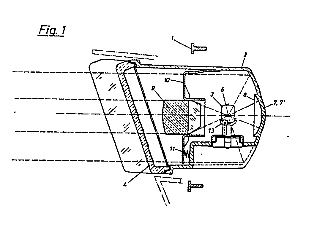
Description
Die Erfindung betrifft eine Fahrzeugleuchte, insbesondere Fahrzeugscheinwerfer, mit einem Strahlenleitsystem, in dem auf eine von der Lichtquelle unabhängig angeordnete, mindestens im wesentlichen die aus der Leuchte austretende Lichtmenge erfassende Projektionslinse gegebenenfalls lediglich eine Abdeckscheibe folgt sowie gegebenenfalls an der der Projektionslinse abgewandten Seite der Lichtquelle ein Reflektor vorgesehen ist.The invention relates to a vehicle lamp, in particular a vehicle headlight, with a radiation guide system in which a projection lens, which is arranged independently of the light source and at least essentially detects the amount of light emerging from the lamp, is optionally followed only by a cover plate and optionally on the side of the light source facing away from the projection lens Reflector is provided.
Der Sehraum des Lenkers eines Kraftfahrzeuges ist sehr breit und verhältnismäßig niedrig. Auch von diesem Sehraum ist nur ein gewisser Bereich ausleuchtbar, da der Gegenverkehr nicht geblendet werden darf. Das klassische Scheinwerfersystem, das außer der Lichtquelle aus zwei optischen Systemen, nämlich einem Parabolreflektor (Homofokalreflektor) und der Abdeckscheibe besteht, eignet sich zu diesem Zweck nur mit gewissen Einschränkungen, da die Riffelung der Abdeckscheibe (d.h. ihre Aufgliederung in Einzellinsengruppen) das einzige Mittel zur Erzielung einer gewünschten Lichtverteilung bietet, wenn man von der Ausbildung des Reflektors als Rechteckreflektor absieht. Hier ist auch zu bedenken, daß die Abdeckscheibe oft aus baulichen Gründen windschief zur optischen Achse des Scheinwerfers stehen muß.The area of the driver of a motor vehicle is very wide and relatively low. Only a certain area of this very space can be illuminated, since oncoming traffic must not be dazzled. The classic headlight system, which in addition to the light source consists of two optical systems, namely a parabolic reflector (homofocal reflector) and the cover plate, is only suitable for this purpose with certain restrictions, since the corrugation of the cover plate (i.e. its division into individual lens groups) is the only means of Achieving a desired light distribution offers, if one refrains from the design of the reflector as a rectangular reflector. It should also be borne in mind here that the cover plate must often be skewed to the optical axis of the headlamp for structural reasons.
Eine weitere Entwicklung, die der Erzielung einer entsprechenden Ausleuchtung hinderlich gegnübersteht, ist die aus stilistischen und aerodynamischen Gründen angestrebte Verkleinerung der Lichtaustrittsfläche.Another development, which hinders the achievement of a corresponding illumination, is the reduction of the light exit surface, which is sought for stylistic and aerodynamic reasons.
Um eine trotzdem entsprechende Leuchtdichte zu erzielen, wurden die sogenannten PE- bzw. DE-Systeme vorgeschlagen, wobei PE für Polyellipsoid und DE für dreidimensionales Ellipsoid steht.In order to achieve a corresponding luminance, the so-called PE or DE systems have been proposed, where PE stands for polyellipsoid and DE for three-dimensional ellipsoid.
Diese Systeme sind in Analogie zu einem Diaprojektor aufgebaut, bei dem das Objekt (das Dia) über ein Objektiv, das im wesentlichen eine Sammellinse ist, abgebildet wird. Demgemäß weisen die PE- bzw. DE-Systeme ebenfalls eine Sammellinse auf, die zwischen der Lichtquelle und der Abdeckscheibe angeordnet ist. Um zum Unterschied vom Diaprojektor eine spezifische Lichtverteilung zu gewährleisten, wobei u.a. die Hell/Dunkelgrenze beim Fahrzeugscheinwerfer ein sehr wesentlicher Faktor ist, sind diese Systeme mit einem besonderen Ellipsoidreflektor und einer Blende ausgestattet, die im Bereich des zweiten Brennpunktes des Ellipsoids angeordnet ist und als Hell/Dunkelgrenze abgebildet wird.These systems are constructed analogously to a slide projector, in which the object (the slide) is imaged via a lens, which is essentially a converging lens. Accordingly, the PE and DE systems also have a converging lens which is arranged between the light source and the cover plate. In order to ensure a specific light distribution, in contrast to the slide projector, whereby the light / dark limit is a very important factor in vehicle headlights, these systems are with one special ellipsoid reflector and an aperture, which is arranged in the area of the second focal point of the ellipsoid and is depicted as a light / dark boundary.
Die PE- bzw. DE-Systeme haben bis jetzt allerdings in der Praxis trotz ihrer optischen Vorzüge keine Verläßlichkeit ergeben, wobei insbesondere das Überhitzungs- und Justierungsproblem eine bedeutende Rolle spielen. Die gekrümmte Objektblende - auch Petzval-Schale genannt - muß nämlich genauestens justiert werden und nimmt eine große Menge an Lichtenergie, die dabei für den angestrebten Zweck verlorengeht, in Form von Wärmeenergie auf, was zur Verformung und Dejustierung der Blende und zur Überhitzung des Scheinwerfers führt. Außerdem ergeben sich Probleme auf Grund des Umstandes, daß die Blendenkante auf Grund ihrer Anordnung im Bereich des zweiten Brennpunktes des Ellipsoidreflektors starke Farbsäume an der Hell/Dunkelgrenze erzeugt.The PE and DE systems have so far, however, in practice, despite their optical advantages, not shown to be reliable, with the overheating and adjustment problem in particular playing an important role. The curved object diaphragm - also called the Petzval bowl - has to be adjusted precisely and absorbs a large amount of light energy, which is lost for the intended purpose, in the form of thermal energy, which leads to the deformation and misalignment of the diaphragm and to overheating of the headlamp . In addition, problems arise due to the fact that the diaphragm edge, due to its arrangement in the region of the second focal point of the ellipsoid reflector, produces strong color fringes at the light / dark boundary.
Die DE-OS 24 61 918 betrifft ein Scheinwerfersystem mit Reflektor, Projektionslinse und dazwischen angeordneter Blende, wobei die beschriebenen und dargestellen Projektionslinsen in üblicher Weise ausgebildet sind. Lediglich Fig. 5 zeigt eine Ausführung ohne eingezeichneter Blende, bei der eine unscharfe Hell/Dunkelgrenze dadurch gebildet ist, daß kein zur Lichtquelle symmetrischer Reflektor, sondern ein elliptischer Hohlspiegelabschnitt vorgesehen ist, dessen zum Glühfaden parallele Kante als Hell/Dunkelgrenze abgebildet wird. Bei dieser Anordung ist aber u.a. die Grundforderung laut Anspruch 1 der DE-OS 24 61 918, nämlich daß die Fläche der Austrittspupille in keiner Richtung größer als 2 cm² ist, nicht erfüllbar auf Grund des Umstandes, daß Direktlicht von der Horizontallampe in die Streulinse eintritt. Zur Erfüllung diese Forderung muß eine Blende vorgesehen sein, die in den anderen Figuren jeweils aufscheint. Fig. 5 ist also als unvollständig anzusehen; ihre Offenbarung ist stets im Rahmen der Gesamtoffenbarung zu sehen.DE-OS 24 61 918 relates to a headlamp system with reflector, projection lens and diaphragm arranged between them, the described and illustrated projection lenses being designed in a conventional manner. Only FIG. 5 shows an embodiment without a drawn-in diaphragm, in which an unsharp light / dark boundary is formed by the fact that an elliptical concave mirror section is provided instead of a reflector symmetrical to the light source, the edge of which parallel to the filament is depicted as a light / dark boundary. With this arrangement, among other things, the basic requirement according to
Die DE-OS 32 41 826 betrifft das bekannte PE-System mit einem elliptischen Reflektor mit zwei Brennpunkten (F₁,F₂) und einer Sammellinse, wobei eine Strahlenblende im zweiten Brennpunkt F₂ angeordnet ist sowie der Brennpunkt der Sammellinse ebenfalls mit F₂ zusammenfällt. Gemäß dieser Druckschrift geht es darum, kritische Zonen am elliptischen Reflektor zu ermitteln und diese durch Oberflächenbehandlung nicht re flektierend oder weniger reflektierend zu machen, bzw. ihre Form zu ändern.DE-OS 32 41 826 relates to the known PE system with an elliptical reflector with two focal points (F₁, F₂) and a converging lens, with a radiation diaphragm being arranged in the second focal point F₂ and the focal point of the converging lens also coinciding with F₂. According to this document, it is a matter of determining critical zones on the elliptical reflector and not re-treating them by surface treatment to make it reflective or less reflective, or to change its shape.
Die FR-A 2501333 betrifft ein optisches System, das vom gegenständlichen optischen System, wo auf die Projektionslinse lediglich gegebenenfalls eine Abdeckscheibe folgt, somit die Projektionslinse das Abbildungsmuster erzeugt, gänzlich verschieden ist. Soweit dort überhaupt Projektionslinsen verwendet werden, folgen auf diese reinen Zerstreuerlinsen Blendenkanten sowie Umlenkspiegel, die das Licht gegen den Reflektor umleiten, von wo es erst in Richtung Abdeckscheibe reflektiert wird. Dementsprechend ist auch eine im Hinblick auf das Abbildungsmuster abschnittsweise unterschiedliche Krümmung der Projektionslinsen nicht vorgesehen; sie projizieren das Licht nicht nach außerhalb des Scheinwerfers.FR-A 2501333 relates to an optical system which is completely different from the objective optical system, where only a cover disk may follow the projection lens, so that the projection lens produces the imaging pattern. Insofar as projection lenses are used at all, these pure diffuser lenses are followed by diaphragm edges and deflecting mirrors, which redirect the light towards the reflector, from where it is only reflected in the direction of the cover plate. Accordingly, a curvature of the projection lenses that is different in sections with respect to the imaging pattern is also not provided; they do not project the light outside the headlight.
Die GB-PS 1 570 805 betrifft einen Scheinwerfer mit einem konkaven Reflektor, der in der Horizontalebene lichtdurchlässig ausgebildet ist, so daß dort vom Reflektor nicht abgelenktes Licht einen Lichtstrahl bildet, der gegenüber dem Hauptlichstrahl geneigt ist. Insbesondere ist der Reflektor geteilt. Dabei können nach verschiedenen Ausführungsformen Glühlampen vorgesehen sein, bei denen an einem üblichen Kolben ein Bikonvexlinsenabschnitt als Stirnteil zur Erfassung des Nahbereichs der optischen Achse vorgsehen ist. Diese Stirnteile erfassen lediglich einen Teil des ausgestrahlten Lichts und weisen überdies zwar zwei unterschiedlich gekrümmte Konvexbereiche auf, die aber in sich gleich gekrümmt sind. Auch die ebenfalls möglichen linsenartigen Ausbildungen der Abdeckscheibe erfassen lediglich im wesentlichen den Nahbereich der optischen Achse.GB-
Endlich betrifft die DE-OS 32 00 796 die Ausbildung einer Abblendkappe für Abblendscheinwerfer, bei denen ein üblicher Reflektor (insbesondere Parabolreflektor), eine Lampe und zwischen Lampe und Reflektor diese Abblendkappe vorgesehen ist. Die Abblendkappe weist eine zur Lichtquelle hin konkave Fläche auf, in der Bereiche unterschiedlicher Krümmung aneinander anschließen.Finally, DE-OS 32 00 796 relates to the construction of a dimming cap for dipped-beam headlamps, in which a conventional reflector (in particular a parabolic reflector), a lamp and this dimming cap is provided between the lamp and the reflector. The anti-dazzle device has a surface concave towards the light source, in which areas of different curvature adjoin one another.
Es wurde nunmehr überraschenderweise gefunden, daß bei Verwendung einer Projecktionslinse die Anordnung einer Objektblende nicht notwendig ist, somit die genannten Probleme ausschaltbar sind.It has now surprisingly been found that the arrangement of an object diaphragm is not necessary when using a projection lens, and thus the problems mentioned can be eliminated.
Demgemäß ist die erfindungsgemäße Fahrzeugleuchte vor allem dadurch gekennzeichnet, daß eine abschnittsweise mit unterschiedlichen Flächenkrümmungen versehene Projektionslinse, die insbesondere in Richtung auf die Lichtquelle von einer gekrümmten Fläche begrenzt ist, ohne Zwischenschaltung einer Blende zwischen Lichtquelle und Projektionslinse und vorzugsweise gegenüber der Lichtquelle verstellbar angeordnet ist.Accordingly, the vehicle lamp according to the invention is primarily characterized in that a projection lens provided in sections with different surface curvatures, which is delimited in particular in the direction of the light source by a curved surface, is arranged so as to be adjustable without the interposition of a diaphragm between the light source and the projection lens and preferably relative to the light source.
Die gewünschte Lichtverteilung wird dabei durch die entsprechende abschnittsweise unterschiedliche Oberflächenkrümmung der Projektionslinsenflächen erzielt. Mit anderen Worten ist die Projektionslinse im Hinblick auf das gewünschte Abbildungsmuster, d.h. die Form des erzeugten Lichtflecks und dessen Leuchtdichteverteilung, korrigiert. Bei Verwendung eines Reflektors wird dabei vorteilhaft die Projektionslinse auch auf den Lichteintritt abgestimmt. Dabei ist die durch Gußverfahren erzielbare Genauigkeit ausreichend. Abschnittsweise unterschiedliche Oberflächenkrümung bedeutet somit, daß an mindestens einer der Flächen, die die Oberfläche der Projektionslinse bilden, Krümmungen vorliegen, die sich voneinander unterscheiden.The desired light distribution is achieved by the corresponding section curvature of the projection lens surfaces. In other words, the projection lens is in view of the desired imaging pattern, i.e. corrected the shape of the generated light spot and its luminance distribution. When using a reflector, the projection lens is advantageously also matched to the entry of light. The accuracy that can be achieved by casting processes is sufficient. Surface curvature which differs in sections thus means that curvatures which differ from one another are present on at least one of the surfaces which form the surface of the projection lens.
Ein wesentlicher Vorteil bei der Erzielung des gewünschten Abbildungsmusters wird erreicht, wenn die Projektionslinse dabei Flachbereiche zur Strahlenbündelung durch Totalreflexion aufweist.A significant advantage in achieving the desired imaging pattern is achieved if the projection lens has flat areas for beam bundling by total reflection.
Zur Begrenzung des Lichtaustritts werden dabei vorteilhaft Randbereiche der Projektionslinse lichtundurchlässig abgedeckt. Dies kann günstig durch die Projektionslinsenhalterung oder durch die Leuchtenmaske selbst erfolgen, d.h. durch den äußeren Leuchtenrand.In order to limit the light emission, edge regions of the projection lens are advantageously covered opaque. This can be done cheaply by the projection lens holder or by the lamp mask itself, i.e. through the outer edge of the lamp.
Eine Abdeckscheibe ist dabei nicht unbedingt erforderlich, so daß die Projektionslinse dann die Leuchtenstirnfläche bildet. Eine Abdeckscheibe kann aber in gewissen Fällen vorteilhaft sein.A cover plate is not absolutely necessary, so that the projection lens then forms the face of the lamp. A cover plate can, however, be advantageous in certain cases.
Vorzugsweise ist die Projektionslinse, zusammen mit und/oder gegenüber ihrer Halterung mit Bezug auf die Lichtquelle zur Justierung verstellbar. Hier ist keine optische Genauigkeit - wie sie bei einer Blende unumgänglich ist - erforderlich. Dies ist insbesondere eine räumliche Verstellbarkeit; je nach Bauart kann aber eine Kipp-, Schwenk- oder Verschiebungsverstellung ausreichen.The projection lens is preferably adjustable for adjustment together with and / or relative to its holder with respect to the light source. No optical accuracy is required here - as is essential for a diaphragm. This is particularly a spatial adjustability; depending on the design, a tilt, swivel or displacement adjustment may be sufficient.
Auf Grund des Umstandes, daß bei der erfindungsgemäßen Leuchte - bis auf Abdeckungen im Randbereich - die volle Lichtmenge zur Beleuchtung zur Verfügung steht, ist auch ein Reflektor nicht unbedingt erforderlich, wohl aber vorteilhaft.Due to the fact that in the luminaire according to the invention - except for covers in the edge area - the full amount of light for lighting Is available, a reflector is not absolutely necessary, but it is advantageous.
Ein besonders günstig anwendbarer Reflektor ist dadurch gekennzeichnet, daß im Nahbereich der Lichtquelle, insbesondere im Bereich der stärksten Reflektorkrümmung, der Reflektor mindestens zwei unabhängig voneinander gekrümmte, vorzugsweise bezüglich der Lichtquelle symmetrisch angeordnete, von der Lichtquelle weggewölbte Abschnitte aufweist bzw. aus diesen Abschnitten gebildet ist.A reflector which can be used particularly advantageously is characterized in that in the vicinity of the light source, in particular in the region of the strongest reflector curvature, the reflector has at least two independently curved sections, preferably arranged symmetrically with respect to the light source, and arched away from the light source or is formed from these sections .
Diese Abschnitte weisen vorteilhaft Kugeloberflächenprofile, vorzugsweise mit gleichem Radius, auf und sind günstig aneinanderstoßend angeordnet, wobei vorzugsweise eine Stoßkante gebildet ist, die von der optischen Achse der Fahrzeugleuchte geschnitten wird.These sections advantageously have spherical surface profiles, preferably of the same radius, and are advantageously arranged abutting one another, wherein a butt edge is preferably formed, which is cut by the optical axis of the vehicle lamp.
Bei der erfindungsgemäßen Fahrzeugleuchte werden insbesondere Lichtquellen so eingesetzt, daß deren Glühfaden im wesentlichen im rechten Winkel zur optischen Achse der Leuchte, vorzugsweise zumindest in einer Projektion parallel zu einer Lichtaustrittsbegrenzungskante, verläuft. So verläuft vorteilhaft der Glühfaden parallel zur Fahrbahn im rechten Winkel zur optischen Achse der Leuchte. Als Beispiel dazu wird eine H₁-Glühlampe, die eine Axialwendel aufweist, von der Seite her oder eine H₃-Glühlampe, die eine Transversalwendel aufweist, von oben oder unten her eingesetzt.In the vehicle lamp according to the invention, light sources in particular are used in such a way that their filament runs essentially at right angles to the optical axis of the lamp, preferably at least in a projection parallel to a light exit boundary edge. The filament advantageously runs parallel to the road at a right angle to the optical axis of the lamp. As an example of this, an
Besonders vorteilhaft wird die erfindungsgemäße Leuchte mit an einen gekrümmten Reflektorbereich nach oben und unten anschließenden abgeflachten Reflektorbereichen, insbesondere als Rechteckleuchte, ausgebildet.The luminaire according to the invention is particularly advantageously designed with flattened reflector regions adjoining a curved reflector region upwards and downwards, in particular as a rectangular luminaire.
Der Reflektor kann auch außerhalb des Bereiches der gewölbten Abschnitte mit Stufen versehen sein.The reflector can also be provided with steps outside the area of the curved sections.
Insbesondere ist die erfindungsgemäße Fahrzeugleuchte als Doppelleuchte mit unabhängigen Lichtquellen, die vorzugsweise jeweils an einander gegenüberliegenden Seiten der Doppelleuchte eingesetzt sind, ausgebildet. Dies bezieht sich vor allem auf übereinander angeordnete Leuchten, bei denen eine Glühlampe von oben und die andere von unten eingesetzt ist. Der Einsatz beider Lampen von hinten oder seitlich ist gleichfalls möglich.In particular, the vehicle lamp according to the invention is designed as a double lamp with independent light sources, which are preferably used on opposite sides of the double lamp. This mainly relates to luminaires arranged one above the other, where one light bulb is inserted from above and the other from below. It is also possible to use both lamps from the rear or from the side.
Weiterhin kann im Bereich der Lichtquelle mindestens eine Abschirmung zur Vermeidung der Weiterleitung von am Lichtquellenkolben und/oder -sockel auftretenden Reflexionen an die Projektionslinse vorgesehen sein.Furthermore, at least one shield can be provided in the region of the light source in order to avoid the forwarding of reflections occurring at the light source bulb and / or base to the projection lens.
Die gezielte Strahlenbündelung gestattet es, die erfindungsgemäße Fahrzeugleuchte für alle Belange der Kraftfahrzeugaußenbeleuchtung, insbesondere für Abblend-, Nebel- oder Fernscheinwerfer, aber auch für Positions- oder Bremsleuchten oder Rückfahrscheinwerfer, einzusetzen.The targeted beam bundling makes it possible to use the vehicle lamp according to the invention for all matters relating to vehicle exterior lighting, in particular for low-beam, fog or high-beam headlamps, but also for position or brake lights or reversing lights.
Die Erfindung wird im folgenden an Hand von Beispielen unter Bezugnahme auf die Zeichnung näher beschrieben, in der Fig. 1 einen Vertikalschnitt und Fig. 2 einen Horizontalschnitt durch einen erfindungsgemäßen Scheinwerfer sowie Fig. 3 einen Horizontalschnitt durch eine Variante des Scheinwerfers nach den Fig. 1 und 2 darstellt.The invention is described in more detail below using examples with reference to the drawing, in which FIG. 1 shows a vertical section and FIG. 2 shows a horizontal section through a headlight according to the invention, and FIG. 3 shows a horizontal section through a variant of the headlight according to FIG. 1 and Figure 2.
In den Figuren ist ein Rechteckscheinwerfer mit einer Halterung 1, einem Reflektor 2, einer Glühlampe 3 und einer Abdeckscheibe 4 dargestellt. Man erkennt, daß die Abdeckscheibe 4 windschief zur optischen Achse 5 des Scheinwerfers angeordnet ist, d.h. sie ist sowohl gegenüber der vertikalen als auch der horizontalen Reflektorsymmetrieebene geneigt.In the figures, a rectangular spotlight with a
Die Glühlampe 3 ist von unter her eingesetzt, ihre Wendel 6 steht horizontal und in der Horizontal-Projektion parallel zur oberen und unteren Lichtaustrittsbegrenzunskante des Scheinwerfers.The
Der Reflektor 2 ist ein Parabolreflektor, der im Bereich seiner stärksten Krümmung zwei zur optischen Achse 5 symmetrisch angeordnete, von der Glühlampe 3 weggewölbte Abschnitte 7,7ʹ aufweist, deren Stoßkante 8 von der optischen Achse 5 geschnitten wird. Die gewölbten Abschnitte 7,7ʹ weisen ein Kugeloberflächenprofil mit gleichen Radien auf.The
Zwischen der Glühlampe 3 und der Abdeckscheibe 4 ist eine Projektionslinse 9 in einer Linsenhalterung 10 vorgesehen. Die Projektionslinse 9 ist eine flache Keillinse, die sowohl an der Lichteintrittsseite als auch an der Lichtaustrittsseite von der Glühlampe 3 weggewölbt ist; sie erfüllt somit die Funktion einer kombinierten Sammel- und Streulinse. Dabei ist die Lichteintrittsseitenwölbung eine Zylinderfläche, die Lichtaustrittsseitenwölbung eine korrigierte Toroidfläche. In Fig. 1 erkennt man, daß der untere Flachbereich der Projektionslinse 9 kürzer ist als deren oberer Flachbereich. Die Flachbereiche der Projektionslinse 9 dienen u.a. der Strahlenbündelung durch Totalreflexion.A
Die Linsenhalterung 10 ist gegenüber der Glühlampe 3 verstellbar vorgesehen, wobei dargestellt ist, daß die Linsenhalterung oben fest mit dem Reflektorkörper 2 verbunden und unten eine Schraubverstellung mit Druckfeder 11 vorgesehen ist.The
Weiterhin erkennt man, daß die Projektionslinse 9 gegenüber der optischen Achse 5 zweifach asymmetrisch angeordnet ist. Eine einfach asymmetrische oder eine symmetrische Anordnung ist gleichfalls möglich.Furthermore, it can be seen that the
In Fig. 3 erkennt man, daß der Reflektor 2 außerhalb der gewölbten Abschnitte 7,7ʹ mit einer zusätzlichen Stufe 12 versehen ist. Die Stufe 12 kann auch beidseitig der Glühlampe 3 angeordnet sein und dient zur Bündelung von Randstrahlen in bevorzugten Bereichen.In Fig. 3 it can be seen that the
In den Figuren sind verschiedene Strahlengänge eingezeichnet. Gegebenenfalls können Bereiche der Projektionslinse 9 verspiegelt sein, insbesondere die oberen und unteren Flachbereiche. Dies gilt ebenso für Teile der Halterung 10, insbesondere im Bereich, wo von den gewölbten Abschnitten 7,7ʹ des Reflektors 2 gebündeltes Licht auftrifft.Various beam paths are shown in the figures. Areas of the
Wie aus Fig. 1 erkennbar, können die Abdeckscheiben, wenn sie verwendet werden, auch eine entsprechende Riffelung aufweisen.As can be seen from FIG. 1, the cover disks, if they are used, can also have a corresponding corrugation.
Bei der in den Fig. 1 und 2 dargestellen Ausführungsform ist eine Abschirmung 13 dargestellt, die den Lampenschaft und den unteren Teil des Lampenkolbens etwa halbkreisförmig umfaßt, ihn aber auch - insbesondere im Kolbenbereich - ganz umgreifen kann. Diese Abschirmung kann dazu eingesetzt werden, zu verhindern, daß Reflexionen, die am Lampenkolben (z.B. durch den Kolbeneinzug der dargestellten H3-Lampe) und/oder am Lampensockel auftreten, als zweite und dritte Brennpunkte der Lampe erscheinen und an die Reflexionslinse abgestrahlt werden.In the embodiment shown in FIGS. 1 and 2, a
Gemäß der Erfindung kann somit die jeweils gewünschte Lichtverteilung und Leuchtdichte ohne die Anordnung erwärmungsempfindlicher Hell/Dunkelblenden erzielt werden; weiterhin ist die Herstellung eines erfindungsgemäß ausgebildeten Reflektors weitaus einfacher als die eines PE- bzw. DE-Reflektors. Die Justierung des optischen Systems ist gleichfalls weitaus weniger aufwendig und anfällig gegenüber der bei den PE- bzw. DE-Systemen.According to the invention, the respectively desired light distribution and luminance can thus be achieved without the arrangement of heat-sensitive light / dark diaphragms; furthermore, the manufacture of a reflector designed according to the invention is far simpler than that of a PE or DE reflector. The adjustment of the optical system is also much less complex and susceptible to that with the PE or DE systems.
Endlich besteht beim erfindungsgemäßen Leuchtensystem - wenn überhaupt - auch nicht die Notwendigkeit, einen bifokalen Reflektor vorzusehen; die Baulänge eines erfindungsgemäßen Scheinwerfers ist also weitaus geringer als die von PE- bzw. DE-Scheinwerfern.Finally, there is no need, if at all, in the lighting system according to the invention to provide a bifocal reflector; the overall length of a headlamp according to the invention is thus far less than that of PE or DE headlamps.
Claims (13)
Applications Claiming Priority (2)
| Application Number | Priority Date | Filing Date | Title |
|---|---|---|---|
| AT0352485A AT396675B (en) | 1985-12-04 | 1985-12-04 | VEHICLE LIGHT |
| AT3524/85 | 1985-12-04 |
Publications (3)
| Publication Number | Publication Date |
|---|---|
| EP0225313A2 true EP0225313A2 (en) | 1987-06-10 |
| EP0225313A3 EP0225313A3 (en) | 1989-05-03 |
| EP0225313B1 EP0225313B1 (en) | 1995-02-08 |
Family
ID=3551702
Family Applications (1)
| Application Number | Title | Priority Date | Filing Date |
|---|---|---|---|
| EP86890322A Expired - Lifetime EP0225313B1 (en) | 1985-12-04 | 1986-11-19 | Vehicle lights |
Country Status (6)
| Country | Link |
|---|---|
| US (1) | US4811174A (en) |
| EP (1) | EP0225313B1 (en) |
| JP (1) | JP2548150B2 (en) |
| AT (2) | AT396675B (en) |
| DE (1) | DE3650229D1 (en) |
| ES (1) | ES2068177T3 (en) |
Cited By (5)
| Publication number | Priority date | Publication date | Assignee | Title |
|---|---|---|---|---|
| EP0623780A3 (en) * | 1993-05-03 | 1995-01-25 | Zizala Lichtsysteme Gmbh | Converging lens for vehicle headlamp. |
| EP0371511B1 (en) * | 1988-11-30 | 1995-06-07 | Ichikoh Industries Limited | Automotive projector-type headlamp |
| EP0725249A1 (en) * | 1995-01-31 | 1996-08-07 | Nippondenso Co., Ltd. | An illuminating device |
| FR2868511A1 (en) * | 2004-03-31 | 2005-10-07 | Koito Mfg Co Ltd | HEADLAMP WITH DECOUPLED BULB |
| AT500415A1 (en) * | 2001-03-13 | 2005-12-15 | Zizala Lichtsysteme Gmbh | VEHICLE HEADLIGHTS |
Families Citing this family (32)
| Publication number | Priority date | Publication date | Assignee | Title |
|---|---|---|---|---|
| FR2621679B1 (en) * | 1987-10-13 | 1990-02-09 | Cibie Projecteurs | LOW HEIGHT HIGH SPEED RECOVERY ROAD PROJECTOR FOR A MOTOR VEHICLE |
| JPH025301A (en) * | 1988-06-24 | 1990-01-10 | Ichikoh Ind Ltd | Headlight for automobile |
| DE68917198T2 (en) * | 1988-05-09 | 1994-11-17 | Ichiko Industries Ltd | Headlights for motor vehicles. |
| GB8824206D0 (en) * | 1988-10-15 | 1988-11-23 | Carello Lighting Plc | Motor vehicle headlamp |
| JPH0515681Y2 (en) * | 1989-02-08 | 1993-04-26 | ||
| US5081564A (en) * | 1989-07-11 | 1992-01-14 | Koito Manufacturing Co., Ltd. | Vehicular lighting device |
| DE3933540C2 (en) * | 1989-10-07 | 1999-04-01 | Bosch Gmbh Robert | Headlights with a variable position of a light source arranged therein for motor vehicles |
| JPH076564Y2 (en) * | 1990-04-19 | 1995-02-15 | 株式会社小糸製作所 | Variable light distribution vehicle headlights |
| JP2787744B2 (en) * | 1992-09-04 | 1998-08-20 | 株式会社小糸製作所 | Reflector for vehicle lighting |
| US5795057A (en) * | 1995-04-17 | 1998-08-18 | Dedo Weigert Film Gmbh | Asymmetrical lamp |
| US5915831A (en) * | 1996-11-05 | 1999-06-29 | Autosystems Manufacturing, Inc. | Internal aim headlamp assembly |
| AUPS198202A0 (en) * | 2002-04-26 | 2002-06-06 | Ferguson Lighting Pty Limited | Lighting apparatus |
| JP4379673B2 (en) * | 2002-10-07 | 2009-12-09 | 株式会社小糸製作所 | Vehicle headlamp |
| US7021796B2 (en) * | 2003-01-13 | 2006-04-04 | The Boeing Company | Light engine apparatus and method |
| US20050030759A1 (en) * | 2003-08-04 | 2005-02-10 | Guide Corporation | Bifocal hyperbolic catadioptric collection system for an automotive lamp |
| JP4536479B2 (en) * | 2003-12-02 | 2010-09-01 | 株式会社小糸製作所 | Vehicle headlamp |
| DE102004001486B4 (en) * | 2004-01-09 | 2010-01-28 | Koito Manufacturing Co., Ltd. | vehicle headlights |
| JP2006049190A (en) * | 2004-08-06 | 2006-02-16 | Koito Mfg Co Ltd | Vehicle headlamp |
| US20060209556A1 (en) * | 2005-03-15 | 2006-09-21 | Koito Manufacturing Co., Ltd. | Vehicle lamp |
| FR2884899B1 (en) * | 2005-04-21 | 2007-06-15 | Valeo Vision Sa | LIGHTING MODULE PROVIDING A LUMINOUS BEAM WITH CUT FOR A MOTOR VEHICLE PROJECTOR, AND PROJECTOR COMPRISING SUCH A MODULE |
| JP2007030592A (en) * | 2005-07-25 | 2007-02-08 | Yamaha Motor Co Ltd | LIGHT DEVICE FOR VEHICLE AND MOTORCYCLE HAVING THE LIGHT DEVICE |
| FR2894647B1 (en) * | 2005-12-09 | 2010-03-12 | Holophane Sa | MOTOR VEHICLE PROJECTOR |
| JP4697969B2 (en) * | 2006-03-29 | 2011-06-08 | スタンレー電気株式会社 | Lighting device |
| US7648257B2 (en) * | 2006-04-21 | 2010-01-19 | Cree, Inc. | Light emitting diode packages |
| US7264387B1 (en) | 2006-05-08 | 2007-09-04 | Visteon Global Technologies, Inc. | Reduced depth projector headlamp assembly |
| US7810972B2 (en) * | 2006-10-13 | 2010-10-12 | Visteon Global Technologies, Inc. | Headlamp assembly having an adjustable light beam direction |
| US20080247188A1 (en) * | 2007-04-04 | 2008-10-09 | Magna International Inc. | Complex projector lens for LED headlamp |
| JP4697215B2 (en) * | 2007-11-20 | 2011-06-08 | 市光工業株式会社 | Vehicle lighting |
| JP5167474B2 (en) * | 2008-07-01 | 2013-03-21 | スタンレー電気株式会社 | Projector type lamp |
| FR2936587B1 (en) * | 2008-09-30 | 2014-04-25 | Valeo Vision Sas | "OPTICAL MODULE HAVING AN OPTICAL DEVIATION ELEMENT" |
| JP2014089941A (en) | 2012-10-03 | 2014-05-15 | Koito Mfg Co Ltd | Vehicular lighting unit |
| WO2016198329A1 (en) * | 2015-06-09 | 2016-12-15 | Lumileds Holding B.V. | Headlight module |
Family Cites Families (27)
| Publication number | Priority date | Publication date | Assignee | Title |
|---|---|---|---|---|
| DE297125C (en) * | ||||
| US1422307A (en) * | 1920-01-19 | 1922-07-11 | Salto Salvatore | Projecting device for beams of light |
| US1519737A (en) * | 1921-10-06 | 1924-12-16 | Lyndon Edward | Light projector |
| US1610124A (en) * | 1924-06-30 | 1926-12-07 | Hall C M Lamp Co | No-glare headlight |
| US1889696A (en) * | 1930-07-30 | 1932-11-29 | Pierron Jacques | Projector |
| FR44054E (en) * | 1933-06-19 | 1934-10-11 | Projector | |
| FR778208A (en) * | 1933-09-09 | 1935-03-12 | Anti-glare deflector for concentrated light beam lamps, such as headlight lamps | |
| FR770599A (en) * | 1934-03-23 | 1934-09-17 | Marchal | Device for recovering or concentrating the direct flux in headlamps, in particular automobile headlamps |
| US2192886A (en) * | 1935-07-27 | 1940-03-12 | Philips Nv | Optical system |
| DE1422506A1 (en) * | 1962-09-13 | 1968-12-05 | Rolf Mickley | Reflector cover lens for two-filament light bulbs with dimmed high-beam and near-light in motor vehicle headlights |
| US3325637A (en) * | 1964-03-14 | 1967-06-13 | Honda Gijutsu Kenkyusho Kk | Dust-proof headlight assembly |
| US3354303A (en) * | 1965-10-08 | 1967-11-21 | Case Co J I | Mechanical and electrical plug-in type headlamp mounting |
| DE1274533B (en) * | 1966-01-27 | 1968-08-08 | Westfaelische Metall Ind K G H | Headlights for motor vehicles with a parabolic reflector |
| US3598989A (en) * | 1969-01-02 | 1971-08-10 | Sylvania Electric Prod | Automotive headlight |
| DE2461918A1 (en) * | 1974-01-11 | 1975-07-17 | Faulhaber Fritz | Motor car spot lamp - with narrow angle beam of high intensity and gas discharge light source |
| US4213171A (en) * | 1976-06-24 | 1980-07-15 | Sassmannshausen Knut | Lighting fixture with side escape window |
| US4369488A (en) * | 1979-10-02 | 1983-01-18 | Cibie Projecteurs | Optical system permitting controlled shifting of the beam pattern in headlamps, especially for vehicles |
| FR2498297B1 (en) * | 1981-01-16 | 1985-11-29 | Cibie Projecteurs | IMPROVEMENTS ON CROSSING PROJECTORS |
| FR2501333A1 (en) * | 1981-03-09 | 1982-09-10 | Cibie Projecteurs | Automotive signal lamp preventing phantom signals - uses shielded lamp with shaped screen immediately ahead to divert all light onto main reflector and to trap incident light |
| US4569007A (en) * | 1981-10-29 | 1986-02-04 | Ford Motor Company | Headlamp |
| FR2516203B1 (en) * | 1981-11-12 | 1986-03-14 | Cibie Projecteurs | MOTOR VEHICLE PROJECTOR |
| US4471411A (en) * | 1982-09-27 | 1984-09-11 | General Motors Corporation | Vehicle body taillamp assembly |
| IT8352827V0 (en) * | 1983-01-11 | 1983-01-11 | Fiat Auto Spa | COLORED LIGHT SIGNALING LIGHT FOR MOTOR VEHICLES |
| JPS59156302U (en) * | 1983-04-07 | 1984-10-20 | 市光工業株式会社 | automotive lighting |
| EP0125353B1 (en) * | 1983-05-10 | 1989-10-11 | Corning Glass Works | Automotive headlight having optics in the reflector |
| FR2566721B1 (en) * | 1984-07-02 | 1987-01-02 | Cibie Projecteurs | METHOD OF MANUFACTURING AND ADJUSTING, IN ORIENTATION, OF A MOTOR VEHICLE PROJECTOR; MOTOR VEHICLE SPOTLIGHT FOR IMPLEMENTING THIS PROCESS |
| DE3529546C1 (en) * | 1985-08-17 | 1987-02-05 | Hella Kg Hueck & Co | Dimmed vehicle headlights with an ellipsoidal reflector |
-
1985
- 1985-12-04 AT AT0352485A patent/AT396675B/en not_active IP Right Cessation
-
1986
- 1986-11-19 AT AT86890322T patent/ATE118264T1/en not_active IP Right Cessation
- 1986-11-19 DE DE3650229T patent/DE3650229D1/en not_active Expired - Fee Related
- 1986-11-19 ES ES86890322T patent/ES2068177T3/en not_active Expired - Lifetime
- 1986-11-19 EP EP86890322A patent/EP0225313B1/en not_active Expired - Lifetime
- 1986-12-02 US US06/936,805 patent/US4811174A/en not_active Expired - Fee Related
- 1986-12-04 JP JP61289749A patent/JP2548150B2/en not_active Expired - Lifetime
Cited By (7)
| Publication number | Priority date | Publication date | Assignee | Title |
|---|---|---|---|---|
| EP0371511B1 (en) * | 1988-11-30 | 1995-06-07 | Ichikoh Industries Limited | Automotive projector-type headlamp |
| EP0623780A3 (en) * | 1993-05-03 | 1995-01-25 | Zizala Lichtsysteme Gmbh | Converging lens for vehicle headlamp. |
| EP0725249A1 (en) * | 1995-01-31 | 1996-08-07 | Nippondenso Co., Ltd. | An illuminating device |
| US5692823A (en) * | 1995-01-31 | 1997-12-02 | Nippondenso Co., Ltd. | Illuminating device |
| AT500415A1 (en) * | 2001-03-13 | 2005-12-15 | Zizala Lichtsysteme Gmbh | VEHICLE HEADLIGHTS |
| AT500415B1 (en) * | 2001-03-13 | 2006-04-15 | Zizala Lichtsysteme Gmbh | VEHICLE HEADLIGHTS |
| FR2868511A1 (en) * | 2004-03-31 | 2005-10-07 | Koito Mfg Co Ltd | HEADLAMP WITH DECOUPLED BULB |
Also Published As
| Publication number | Publication date |
|---|---|
| EP0225313A3 (en) | 1989-05-03 |
| US4811174A (en) | 1989-03-07 |
| EP0225313B1 (en) | 1995-02-08 |
| DE3650229D1 (en) | 1995-03-23 |
| ES2068177T3 (en) | 1995-04-16 |
| ATE118264T1 (en) | 1995-02-15 |
| JP2548150B2 (en) | 1996-10-30 |
| JPS6366801A (en) | 1988-03-25 |
| AT396675B (en) | 1993-11-25 |
| ATA352485A (en) | 1987-07-15 |
Similar Documents
| Publication | Publication Date | Title |
|---|---|---|
| EP0225313B1 (en) | Vehicle lights | |
| EP0208895B1 (en) | Dipped beam head light or fog light for motor vehicles | |
| DE10101258B4 (en) | vehicle headlights | |
| DE69829895T2 (en) | headlights | |
| DE102005020866B4 (en) | Vehicle headlights | |
| DE102004043706B4 (en) | Optical system for a motor vehicle headlight, lighting unit for a motor vehicle headlight and motor vehicle headlight | |
| DE3620789C2 (en) | Dimmed automotive headlights | |
| DE19961942B4 (en) | Headlamp system for vehicles for generating light bundles with different characteristics | |
| DE19860669B4 (en) | Vehicle headlights according to the projection principle | |
| DE4315393A1 (en) | Headlamp (headlight) for vehicles | |
| DE19508472A1 (en) | Vehicle headlight that has a simplified structure and reduced condensation | |
| DE112011104718T5 (en) | Projection projector with maximized light collection efficiency | |
| EP0294589B1 (en) | Dipped light headlamp | |
| EP0307657A2 (en) | Motor vehicle headlight | |
| DE68917555T2 (en) | Motor vehicle headlights. | |
| DE102006045446B4 (en) | vehicle light | |
| DE4112194C2 (en) | Motor vehicle headlight unit | |
| DE4307109C2 (en) | Low beam headlights for right and left-hand traffic for motor vehicles | |
| DE427143C (en) | Headlight lamp, especially for automobiles, with reflector, projection lens and obturator | |
| DE102015201856A1 (en) | Motor vehicle headlight | |
| DE69013030T2 (en) | Reflector for a lamp. | |
| DE4228890B4 (en) | Headlights for vehicles | |
| DE69832327T2 (en) | Motor vehicle headlight with a two-filament lamp | |
| AT500562B1 (en) | VEHICLE HEADLIGHTS | |
| DE10012634A1 (en) | Head-lamp for motor vehicle, has active rear-wall zone of reflector directly behind the light-source |
Legal Events
| Date | Code | Title | Description |
|---|---|---|---|
| PUAI | Public reference made under article 153(3) epc to a published international application that has entered the european phase |
Free format text: ORIGINAL CODE: 0009012 |
|
| AK | Designated contracting states |
Kind code of ref document: A2 Designated state(s): AT BE CH DE ES FR GB GR IT LI LU NL SE |
|
| PUAL | Search report despatched |
Free format text: ORIGINAL CODE: 0009013 |
|
| AK | Designated contracting states |
Kind code of ref document: A3 Designated state(s): AT BE CH DE ES FR GB GR IT LI LU NL SE |
|
| 17P | Request for examination filed |
Effective date: 19890905 |
|
| 17Q | First examination report despatched |
Effective date: 19910705 |
|
| RAP1 | Party data changed (applicant data changed or rights of an application transferred) |
Owner name: ZIZALA LICHTSYSTEME GMBH |
|
| GRAA | (expected) grant |
Free format text: ORIGINAL CODE: 0009210 |
|
| AK | Designated contracting states |
Kind code of ref document: B1 Designated state(s): AT BE CH DE ES FR GB GR IT LI LU NL SE |
|
| PG25 | Lapsed in a contracting state [announced via postgrant information from national office to epo] |
Ref country code: NL Effective date: 19950208 Ref country code: GR Free format text: LAPSE BECAUSE OF FAILURE TO SUBMIT A TRANSLATION OF THE DESCRIPTION OR TO PAY THE FEE WITHIN THE PRESCRIBED TIME-LIMIT Effective date: 19950208 Ref country code: BE Effective date: 19950208 |
|
| REF | Corresponds to: |
Ref document number: 118264 Country of ref document: AT Date of ref document: 19950215 Kind code of ref document: T |
|
| REF | Corresponds to: |
Ref document number: 3650229 Country of ref document: DE Date of ref document: 19950323 |
|
| REG | Reference to a national code |
Ref country code: ES Ref legal event code: FG2A Ref document number: 2068177 Country of ref document: ES Kind code of ref document: T3 |
|
| GBT | Gb: translation of ep patent filed (gb section 77(6)(a)/1977) |
Effective date: 19950327 |
|
| ITF | It: translation for a ep patent filed | ||
| PG25 | Lapsed in a contracting state [announced via postgrant information from national office to epo] |
Ref country code: SE Effective date: 19950508 |
|
| ET | Fr: translation filed | ||
| NLV1 | Nl: lapsed or annulled due to failure to fulfill the requirements of art. 29p and 29m of the patents act | ||
| PG25 | Lapsed in a contracting state [announced via postgrant information from national office to epo] |
Ref country code: GB Effective date: 19951119 Ref country code: AT Effective date: 19951119 |
|
| PG25 | Lapsed in a contracting state [announced via postgrant information from national office to epo] |
Ref country code: ES Free format text: LAPSE BECAUSE OF NON-PAYMENT OF DUE FEES Effective date: 19951120 |
|
| PG25 | Lapsed in a contracting state [announced via postgrant information from national office to epo] |
Ref country code: LU Free format text: LAPSE BECAUSE OF NON-PAYMENT OF DUE FEES Effective date: 19951130 Ref country code: LI Effective date: 19951130 Ref country code: CH Effective date: 19951130 |
|
| PLBE | No opposition filed within time limit |
Free format text: ORIGINAL CODE: 0009261 |
|
| STAA | Information on the status of an ep patent application or granted ep patent |
Free format text: STATUS: NO OPPOSITION FILED WITHIN TIME LIMIT |
|
| 26N | No opposition filed | ||
| REG | Reference to a national code |
Ref country code: CH Ref legal event code: PL |
|
| GBPC | Gb: european patent ceased through non-payment of renewal fee |
Effective date: 19951119 |
|
| PG25 | Lapsed in a contracting state [announced via postgrant information from national office to epo] |
Ref country code: FR Effective date: 19960731 |
|
| PG25 | Lapsed in a contracting state [announced via postgrant information from national office to epo] |
Ref country code: DE Effective date: 19960801 |
|
| REG | Reference to a national code |
Ref country code: FR Ref legal event code: ST |
|
| REG | Reference to a national code |
Ref country code: ES Ref legal event code: FD2A Effective date: 19961213 |
|
| PG25 | Lapsed in a contracting state [announced via postgrant information from national office to epo] |
Ref country code: IT Free format text: LAPSE BECAUSE OF NON-PAYMENT OF DUE FEES;WARNING: LAPSES OF ITALIAN PATENTS WITH EFFECTIVE DATE BEFORE 2007 MAY HAVE OCCURRED AT ANY TIME BEFORE 2007. THE CORRECT EFFECTIVE DATE MAY BE DIFFERENT FROM THE ONE RECORDED. Effective date: 20051119 |