EP0225265A1 - Injection syringe for dental impression paste incorporating a filling device - Google Patents
Injection syringe for dental impression paste incorporating a filling device Download PDFInfo
- Publication number
- EP0225265A1 EP0225265A1 EP86420283A EP86420283A EP0225265A1 EP 0225265 A1 EP0225265 A1 EP 0225265A1 EP 86420283 A EP86420283 A EP 86420283A EP 86420283 A EP86420283 A EP 86420283A EP 0225265 A1 EP0225265 A1 EP 0225265A1
- Authority
- EP
- European Patent Office
- Prior art keywords
- tube
- syringe
- syringe according
- piston
- injection
- Prior art date
- Legal status (The legal status is an assumption and is not a legal conclusion. Google has not performed a legal analysis and makes no representation as to the accuracy of the status listed.)
- Granted
Links
Images

Classifications
-
- B—PERFORMING OPERATIONS; TRANSPORTING
- B05—SPRAYING OR ATOMISING IN GENERAL; APPLYING FLUENT MATERIALS TO SURFACES, IN GENERAL
- B05C—APPARATUS FOR APPLYING FLUENT MATERIALS TO SURFACES, IN GENERAL
- B05C17/00—Hand tools or apparatus using hand held tools, for applying liquids or other fluent materials to, for spreading applied liquids or other fluent materials on, or for partially removing applied liquids or other fluent materials from, surfaces
- B05C17/005—Hand tools or apparatus using hand held tools, for applying liquids or other fluent materials to, for spreading applied liquids or other fluent materials on, or for partially removing applied liquids or other fluent materials from, surfaces for discharging material from a reservoir or container located in or on the hand tool through an outlet orifice by pressure without using surface contacting members like pads or brushes
- B05C17/00593—Hand tools of the syringe type
-
- A—HUMAN NECESSITIES
- A61—MEDICAL OR VETERINARY SCIENCE; HYGIENE
- A61C—DENTISTRY; APPARATUS OR METHODS FOR ORAL OR DENTAL HYGIENE
- A61C9/00—Impression cups, i.e. impression trays; Impression methods
- A61C9/0026—Syringes or guns for injecting impression material; Mixing impression material for immediate use
-
- B—PERFORMING OPERATIONS; TRANSPORTING
- B05—SPRAYING OR ATOMISING IN GENERAL; APPLYING FLUENT MATERIALS TO SURFACES, IN GENERAL
- B05C—APPARATUS FOR APPLYING FLUENT MATERIALS TO SURFACES, IN GENERAL
- B05C17/00—Hand tools or apparatus using hand held tools, for applying liquids or other fluent materials to, for spreading applied liquids or other fluent materials on, or for partially removing applied liquids or other fluent materials from, surfaces
- B05C17/005—Hand tools or apparatus using hand held tools, for applying liquids or other fluent materials to, for spreading applied liquids or other fluent materials on, or for partially removing applied liquids or other fluent materials from, surfaces for discharging material from a reservoir or container located in or on the hand tool through an outlet orifice by pressure without using surface contacting members like pads or brushes
- B05C17/00503—Details of the outlet element
- B05C17/00516—Shape or geometry of the outlet orifice or the outlet element
Definitions
- the present invention relates to a syringe with incorporated filling system for the injection of pasty products intended for taking dental impressions.
- the alginates composed of powdered algae, which the user at the time of their use must mix in a bowl with water in order to obtain a pasty product, which gels after a few minutes.
- Silicones, thiocols or elastomers which are viscous pastes which are kneaded, before their use on a plate or on a mixing block, with a paste or a catalyst or hardener liquid. These materials also polymerize after a few minutes.
- the object of the invention is to provide a syringe allowing all these problems to be resolved simultaneously.
- the present invention provides a syringe for the injection of pasty products comprising a cylinder in which a piston can slide, and further comprising a sampling tube split over most of its length and provided with a gripping means such as a ring, the internal diameter of the cylinder corresponding substantially to the external diameter of the tube, so that, when the tube is placed in the cylinder, this assembly defines an injection chamber delimited by the internal wall of the tube and, at the opening of the latter, by the internal wall of the cylinder.
- the opening of the slot is between a quarter and a half of the periphery of the tube.
- the main body 1 of the syringe is composed of a tube axially bored to a given diameter (2); it has at its front end 3 a thread into which is screwed a nut 4 blocking the injection nozzle 5. Its rear part comprises a collar 6 intended to hold the syringe body 1 between the fingers of the user.
- the rear orifice of the syringe comprises a chamfer 7 facilitating the penetration of the sampling tube described below.
- the sampling tube 8, of external diameter equal to the bore 2 is split over at least a large part of its length.
- the slot 9 has an opening of between about a quarter and about half the circumference of the tube.
- the end 10 of the tube is beveled or rounded in order to facilitate penetration into the body of the syringe 1 through the chamfered orifice 7. Its rear part passes through a ring 11 used for gripping and handling the assembly.
- the split part 9 also passes through this ring.
- the slot 9 generates two edges 12 which are bevelled (sharpened) in order to be able to scrape the impression material well during the sampling.
- the front opening of the gripping ring 11 is provided with a chamfer 19.
- the rear opening of this ring 11 and therefore of the sampling tube 8 is provided with a chamfer 20.
- the piston 13 comprises in its front part 14, a first annular groove 15 as well as a second groove 16 receiving an O-ring 17.
- This groove 16 is wider than the section of the O-ring 17 and has a diameter smaller than the inside diameter of the seal 17.
- the piston 13 includes a push button 18.
- the user fixes the injection nozzle 5 via the nut 4 on the thread 3 of the main body 1 of the syringe. It has the piston 13 in the sampling tube 8 by making its front part 14 penetrate through the chamfered orifice 20 the O-ring 17 not exceeding the limit of the chamfer 19. The two assemblies thus formed are left waiting during execution of the mixture of the pasty product.
- the user grasps the tube 8 plus piston 13 assembly by the gripping ring 11. He has the slit part 9 facing the product to be removed, one of the edges 12 being in contact with the surface of the block mixing or the wall of the mixing bowl which, it should be specified, is always flexible and has a vertical wall.
- the user moves this assembly while keeping the edge 12 in contact with the mixing surface and thus fills the sampling tube 8 through the slot 9.
- the user After removal, as shown in Figure 6, the user, still holding the grip ring 11, has the beveled or rounded end 10, facing the rear orifice provided with a chamfer 7, and pushes the sampling tube 8 fully into the internal bore 2 of the main body 1 of the syringe.
- the user waits until the material has taken up before cleaning his syringe. It then suffices to remove the piston 13 by turning it slightly.
- the O-ring 17 passes without problem through the internal bore of the grip ring 11 thanks to the chamfer 19.
- the gelled or polymerized material which remained in the injection nozzle 5 remains integral with the end 14 of the piston 13, because having been crimped in the first annular groove 15 of the latter.
- This operation being carried out the user then removes the filling tube 8 from the main body 1, by turning it slightly. The passage of a swab is then enough to clean all the components of this syringe.
Abstract
L'invention concerne un dispositif composé d'un corps principal (1) de seringue à l'extrémité (3) duquel est fixé un embout d'injection (5) par l'intermédiaire d'un écrou (4). Dans l'orifice de sa partie arrière (6) vient coulisser axialement un tube (8) fendu sur toute sa longueur, ayant servi préalablement, par raclage d'une de ses arêtes (12), sur la surface de malaxage, au prélèvement du matériau pâteux. Ce tube (8) de prélèvement possède en sa partie arrière une bague de préhension (11). L'enfoncement axial du tube (8) dans l'alésage interne (2) du corps principal (1) de seringue, permet son remplissage. Pour l'injection du produit pâteux, il suffit alors de pousser le piston (13) par son bouton poussoir (18).The invention relates to a device comprising a main body (1) of a syringe at the end (3) of which is fixed an injection nozzle (5) by means of a nut (4). In the orifice of its rear part (6) slides axially a tube (8) split over its entire length, having previously served, by scraping one of its edges (12), on the mixing surface, for removing the pasty material. This sampling tube (8) has at its rear part a gripping ring (11). The axial insertion of the tube (8) into the internal bore (2) of the main body (1) of the syringe allows it to be filled. For the injection of the pasty product, it then suffices to push the piston (13) by its push button (18).
Description
La présente invention concerne une seringue avec système de remplissage incorporé pour l'injection de produits pâteux destinés à la prise d'empreintes dentaires.The present invention relates to a syringe with incorporated filling system for the injection of pasty products intended for taking dental impressions.
Les chirurgiens dentistes utilisent actuellement pour la prise d'empreintes plusieurs types de matériaux. Tous ces matériaux, au moment de l'injection ont une consistance pâteuse. Les matériaux, non limitatifs, pour lesquels cette invention offre un intérêt particulier sont de deux types.Dental surgeons currently use several types of materials for taking impressions. All these materials, at the time of injection, have a pasty consistency. There are two types of non-limiting materials for which this invention is of particular interest.
Les alginates, composés d'algues en poudre, que l'utilisateur au moment de leur emploi doit mélanger dans un bol avec de l'eau afin d'obtenir un produit pâteux, qui gélifie au bout de quelques minutes.The alginates, composed of powdered algae, which the user at the time of their use must mix in a bowl with water in order to obtain a pasty product, which gels after a few minutes.
Les silicones, thiocols ou élastomères, qui sont des pâtes visqueuses que l'on malaxe, avant leur utilisation sur une plaque ou sur un bloc de mélange, avec une pâte ou un liquide catalyseur ou durcisseur. Ces matériaux polymérisent, eux aussi, au bout de quelques minutes.Silicones, thiocols or elastomers, which are viscous pastes which are kneaded, before their use on a plate or on a mixing block, with a paste or a catalyst or hardener liquid. These materials also polymerize after a few minutes.
Le problème posé par tous ces matériaux est le temps, relativement court, de 2 à 4 minutes en moyenne, dont l'utilisateur dispose entre le moment où il commence le malaxage et le moment où le matériau commence sa prise ou sa gélification, et donc, n'est plus injectable.The problem posed by all these materials is the relatively short time, of 2 to 4 minutes on average, which the user has between the time he begins kneading and the time when the material begins to set or gel, and therefore , is no longer injectable.
Les seringues, destinées à l'injection de ces produits d'empreinte pâteux, posent toutes le problème de leur remplissage, car la section de leur alésage intérieur est faible.The syringes, intended for the injection of these pasty impression products, all pose the problem of their filling, because the cross section of their internal bore is small.
Il existe plusieurs types de techniques ou de systèmes de remplissage. Tout d'abord, dans la majeure partie des cas, les seringues se remplissent en raclant sur le bol de mélange leur partie arrière, afin d'y faire pénétrer, par gravitation le matériau. Cette technique est caractérisée par la mauvaise qualité du remplissage, car elle entraîne nécessairement un mélange d'air et de matériau dans la seringue, induisant, au moment de l'injection, des bulles d'air, très préjudiciables à la qualité de l'empreinte. De plus, il est très difficile, en un minimum de temps, de racler, sur toute la surface du bloc de mélange, la totalité du mélange ; il en résulte une perte de matériau.There are several types of filling techniques or systems. First of all, in most of the cases, the syringes are filled by scraping their rear part on the mixing bowl, in order to make the material penetrate therein. This technique is characterized by poor quality filling, because it necessarily involves a mixture of air and material in the syringe, inducing, at the time of injection, air bubbles, very detrimental to the quality of the impression. In addition, it is very difficult, in a minimum of time, to scrape, over the entire surface of the mixing block, the entire mixture; this results in a loss of material.
Il existe également des seringues avec des systèmes de chargeurs, parties intégrantes ou ajoutées, puis enlevés de l'arrière de la seringue, eux-mêmes remplis avec une spatule servant au prélèvement du matériau sur le bloc de mélange ou dans le bol de malaxage. Ces procédés sont peu satisfaisants car ils entraînent une perte de temps par la manipulation d'accessoires de remplissage, tels que pistons des chargeurs intégrés ou ensembles chargeurs plus pistons amovibles. Ces procédés entraînent également une perte de matériau, et sont souvent d'une manipulation compliquée souillant souvent la seringue.There are also syringes with loading systems, integral or added parts, then removed from the rear of the syringe, themselves filled with a spatula used to withdraw the material from the mixing block or from the mixing bowl. These methods are not very satisfactory because they result in a loss of time by handling filling accessories, such as pistons of integrated magazines or magazine assemblies plus removable pistons. These methods also result in loss of material, and are often complicated to handle often contaminating the syringe.
Il existe enfin des systèmes de seringues à double corps et double pistons, pouvant même servir au malaxage de certains produits d'empreintes très fluides. Ces systèmes n'apportent pas la solution à l'injection de produits moins fluides et, par leur conception, sont souvent peu pratiques, encombrants et inadaptés pour des injections de petites quantités de matériau.Finally, there are double-barrel, double-piston syringe systems, which can even be used for kneading certain very fluid impression products. These systems do not provide the solution to the injection of less fluid products and, by their design, are often impractical, bulky and unsuitable for injecting small quantities of material.
L'examen de ces techniques montre que, si certaines d'entre elles en résolvent une partie, aucune ne résoud entièrement à elle seule tous les problèmes de rapidité d'exécution, d'efficacité, d'économie de matériau, de propreté et de simplicité d'emploi.Examination of these techniques shows that, while some of them solve part of it, none alone solves all the problems of speed of execution, efficiency, economy of material, cleanliness and ease of use.
L'objet de l'invention est de prévoir une seringue permettant de résoudre simultanément tous ces problèmes.The object of the invention is to provide a syringe allowing all these problems to be resolved simultaneously.
Pour atteindre cet objet, la présente invention prévoit une seringue pour l'injection de produits pâteux comprenant un cylindre dans lequel peut coulisser un piston, et comprenant en outre un tube de prélèvement fendu sur la plus grande partie de sa longueur et muni d'un moyen de préhension tel qu'une bague, le diamètre interne du cylindre correspondant sensiblement au diamètre externe du tube, de sorte que, quand le tube est disposé dans le cylindre, cet ensemble définit une chambre d'injection délimitée par la paroi interne du tube et, au niveau de l'ouverture de celui-ci, par la paroi interne du cylindre.To achieve this object, the present invention provides a syringe for the injection of pasty products comprising a cylinder in which a piston can slide, and further comprising a sampling tube split over most of its length and provided with a gripping means such as a ring, the internal diameter of the cylinder corresponding substantially to the external diameter of the tube, so that, when the tube is placed in the cylinder, this assembly defines an injection chamber delimited by the internal wall of the tube and, at the opening of the latter, by the internal wall of the cylinder.
Selon un mode de réalisation de l'invention, l'ouverture de la fente est comprise entre le quart et la moitié de la périphérie du tube.According to one embodiment of the invention, the opening of the slot is between a quarter and a half of the periphery of the tube.
On décrira ci-après un mode de réalisation de la présente invention, en relation avec les figures jointes parmi lesquelles :
- la figure 1 est une vue en coupe du corps principal de la seringue, avec son embout d'injection et un écrou de fixation ;
- la figure 2 est une vue du tube de prélèvement selon l'invention ;
- la figure 3 est une coupe suivant la ligne AA de la figure 2 de ce tube de prélèvement agrandie deux fois ;
- la figure 4 est une vue en coupe d'un piston d'injection ; et
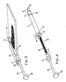
- les figures 5, 6 et 7 sont destinées à illustrer le mode d'utilisation d'une seringue selon la présente invention.
- Figure 1 is a sectional view of the main body of the syringe, with its injection nozzle and a fixing nut;
- Figure 2 is a view of the sampling tube according to the invention;
- Figure 3 is a section along line AA of Figure 2 of this collection tube enlarged twice;
- Figure 4 is a sectional view of an injection piston; and
- Figures 5, 6 and 7 are intended to illustrate the mode of use of a syringe according to the present invention.
Comme le représente la figure 1, le corps principal 1 de la seringue est composé d'un tube alésé axialement selon un diamètre donné (2) ; il comporte à son extrémité avant 3 un filetage où vient se visser un écrou 4 bloquant l'embout d'injection 5. Sa partie arrière comporte une colerette 6 destinée à maintenir le corps de seringue 1 entre les doigts de l'utilisateur. L'orifice arrière de la seringue comporte un chanfrein 7 facilitant la pénétration du tube de prélèvement décrit ci-après.As shown in Figure 1, the main body 1 of the syringe is composed of a tube axially bored to a given diameter (2); it has at its front end 3 a thread into which is screwed a
Comme le représentent les figures 2 et 3, le tube de prélèvement 8, de diamètre extérieur égal à l'alésage 2, est fendu sur au moins une grande partie de sa longueur. La fente 9 a une ouverture comprise entre environ le quart et environ la moitié de la circonférence du tube. L'extrémité 10 du tube est en biseau ou arrondie afin de faciliter la pénétration dans le corps de la seringue 1 par l'orifice chanfreiné 7. Sa partie arrière traverse une bague 11 servant à la préhension et à la manipulation de l'ensemble. La partie fendue 9 traverse également cette bague. La fente 9 génère deux arêtes 12 qui sont taillées en biseau (aiguisées) afin de bien pouvoir racler le matériau d'empreinte lors du prélèvement.As shown in Figures 2 and 3, the sampling tube 8, of external diameter equal to the
L'orifice avant de la bague de préhension 11 est muni d'un chanfrein 19. L'orifice arrière de cette bague 11 et donc du tube de prélèvement 8 est muni d'un chanfrein 20.The front opening of the
Comme le représente la figure 4, le piston 13 comporte en sa partie avant 14, une première rainure annulaire 15 ainsi qu'une deuxième gorge 16 recevant un joint torique 17. Cette gorge 16 est plus large que la section du joint torique 17 et a un diamètre inférieur au diamètre intérieur du joint 17. En sa partie arrière le piston 13 comporte un bouton poussoir 18.As shown in FIG. 4, the
A titre d'exemple, on décrira ci-après une manipulation.By way of example, a manipulation will be described below.
Avant d'effectuer le mélange du produit pâteux d'empreinte, l'utilisateur fixe par l'intermédiaire de l'écrou 4 l'embout d'injection 5 sur le filetage 3 du corps principal 1 de la seringue. Il dispose le piston 13 dans le tube de prélèvement 8 en faisant pénétrer sa partie avant 14 par l'orifice chanfreiné 20 le joint torique 17 ne dépassant pas la limite du chanfrein 19. Les deux ensembles ainsi constitués sont laissés en attente pendant l'exécution du mélange du produit pâteux.Before mixing the pasty impression product, the user fixes the
Le mélange réalisé, l'utilisateur saisit par la bague de préhension 11 l'ensemble tube 8 plus piston 13. Il dispose la partie fendue 9 face au produit à prélever, l'une des arêtes 12 étant au contact de la surface du bloc de malaxage ou de la paroi du bol de mélange qui, il faut le préciser, est toujours souple et possède une paroi verticale.When the mixture has been produced, the user grasps the tube 8
Comme cela est représenté en figure 5, l'utilisateur déplace cet ensemble en maintenant l'arête 12 au contact de la surface de mélange et remplit ainsi par la fente 9 le tube de prélèvement 8.As shown in FIG. 5, the user moves this assembly while keeping the
Après le prélèvement, comme cela est représenté en figure 6, l'utilisateur, tenant toujours la bague de préhension 11, présente l'extrémité 10 biseautée ou arrondie, face à l'orifice arrière muni d'un chanfrein 7, et pousse à fond le tube de prélèvement 8 dans l'alésage interne 2 du corps principal 1 de la seringue.After removal, as shown in Figure 6, the user, still holding the
Cette opération effectuée, il ne lui reste plus, comme cela est représenté en figure 7, qu'à injecter le produit pâteux en appuyant, par le bouton poussoir 18, pour faire pénétrer le piston 13 dans l'ensemble corps principal 1 de seringue plus tube de prélèvement 8. Il agit alors comme avec une seringue classique.Once this has been done, all that remains, as shown in FIG. 7, is to inject the pasty product by pressing, using the
L'injection étant achevée, l'utilisateur attend que le matériau ait effectué sa prise avant de nettoyer sa seringue. Il suffit alors de retirer le piston 13 en le tournant légèrement. Le joint torique 17 passe sans problème par l'alésage interne de la bague de préhension 11 grâce au chanfrein 19. Le matériau gélifié ou polymérisé qui demeurait dans l'embout d'injection 5 restant solidaire de l'extrémité 14 du piston 13, car s'étant serti dans la première rainure annulaire 15 de ce dernier. Cette opération étant effectuée, l'utilisateur retire ensuite le tube de remplissage 8 du corps principal 1, en le tournant légèrement. Le passage d'un écouvillon suffit alors au nettoyage de tous les éléments composant cette seringue.Once the injection is complete, the user waits until the material has taken up before cleaning his syringe. It then suffices to remove the
L'exposé de cette manipulation démontre sa simplicté, sa rapidité, et l'efficacité du remplissage de cette seringue, évitant ainsi toute perte de temps et toute perte de matériau.The presentation of this manipulation demonstrates its simplicity, its speed, and the efficiency of filling this syringe, thus avoiding any loss of time and any loss of material.
Claims (9)
Applications Claiming Priority (2)
| Application Number | Priority Date | Filing Date | Title |
|---|---|---|---|
| FR8517550 | 1985-11-25 | ||
| FR8517550A FR2590487A1 (en) | 1985-11-25 | 1985-11-25 | SYRINGE FOR INJECTING PASTY PRODUCTS FOR DENTAL FINGER PRINTING WITH INCORPORATED FILLING DEVICE |
Publications (2)
| Publication Number | Publication Date |
|---|---|
| EP0225265A1 true EP0225265A1 (en) | 1987-06-10 |
| EP0225265B1 EP0225265B1 (en) | 1991-04-24 |
Family
ID=9325202
Family Applications (1)
| Application Number | Title | Priority Date | Filing Date |
|---|---|---|---|
| EP86420283A Expired - Lifetime EP0225265B1 (en) | 1985-11-25 | 1986-11-20 | Injection syringe for dental impression paste incorporating a filling device |
Country Status (5)
| Country | Link |
|---|---|
| US (1) | US4784607A (en) |
| EP (1) | EP0225265B1 (en) |
| DE (1) | DE3678910D1 (en) |
| ES (1) | ES2021606B3 (en) |
| FR (1) | FR2590487A1 (en) |
Cited By (2)
| Publication number | Priority date | Publication date | Assignee | Title |
|---|---|---|---|---|
| US6848906B2 (en) | 2000-12-05 | 2005-02-01 | Heraeus Kulzer Gmbh & Co. Kg | Syringe for the metered delivery of dental materials |
| FR2937313A1 (en) * | 2008-10-21 | 2010-04-23 | Prophytec | CAPSULE AND METHOD FOR DISTRIBUTING A PRODUCT |
Families Citing this family (26)
| Publication number | Priority date | Publication date | Assignee | Title |
|---|---|---|---|---|
| US5236355A (en) * | 1988-12-22 | 1993-08-17 | American Cyanamid Company | Apparatus for the treatment of periodontal disease |
| US5122057A (en) * | 1991-01-07 | 1992-06-16 | Centrix, Inc. | Dosing dental cartridge |
| US5165890A (en) * | 1991-01-07 | 1992-11-24 | Centrix, Inc. | Dosing dental cartridge |
| US5267859A (en) * | 1991-01-07 | 1993-12-07 | Centrix, Inc. | Bulk dental cartridge |
| US5324273A (en) * | 1992-09-30 | 1994-06-28 | Centrix, Inc. | Disposable barrel dental impression material syringe |
| US5322440A (en) * | 1992-10-20 | 1994-06-21 | Kerr Manufacturing Company | Dental syringe tip |
| US5387103A (en) * | 1993-02-16 | 1995-02-07 | Ultradent Products, Inc. | Syringe apparatus for delivering tooth composites and other solid yet pliable materials |
| US5451214A (en) * | 1993-03-22 | 1995-09-19 | Hajishoreh; Kaveh-Karimi | Syringe apparatus |
| US5445523A (en) * | 1993-09-03 | 1995-08-29 | Ultradent Products, Inc. | Syringe apparatus and methods for dispensing viscous materials |
| DE9419200U1 (en) * | 1994-11-30 | 1996-04-11 | Muehlbauer Ernst Kg | Dental mass application device |
| US6554803B1 (en) * | 1997-04-02 | 2003-04-29 | Arthur Ashman | Combination syringe and aspirator for bone regeneration material and method for using the syringe |
| US20020119417A1 (en) * | 1998-05-29 | 2002-08-29 | Arthur Ashman | Nozzle tip for use with syringe and method for using same |
| US7563249B2 (en) * | 2002-12-20 | 2009-07-21 | Medrad, Inc. | Syringe having an alignment flange, an extending lip and a radial expansion section of reduced wall thickness |
| US6638065B2 (en) | 2001-12-17 | 2003-10-28 | Ultradent Products, Inc. | Quad cutter tool for removing syringe divider |
| US6682348B2 (en) * | 2002-03-29 | 2004-01-27 | Orapharma, Inc. | Dispensing apparatus and cartridge |
| JP2005527361A (en) * | 2002-05-28 | 2005-09-15 | ケルサン テクノロジーズ コープ. | Spray nozzle assembly |
| US7513901B2 (en) * | 2005-05-19 | 2009-04-07 | Warsaw Orthopedic, Inc. | Graft syringe assembly |
| CA2567936C (en) | 2006-11-14 | 2016-01-05 | Atomic Energy Of Canada Limited | Device and method for surface replication |
| US7976490B2 (en) * | 2007-12-04 | 2011-07-12 | Orapharma, Inc. | Medicinal implant cartridge |
| US7976491B2 (en) * | 2007-12-04 | 2011-07-12 | Orapharma, Inc. | Actuators for device for delivering medicinal implants |
| US7976489B2 (en) | 2007-12-04 | 2011-07-12 | Orapharma, Inc. | Device for delivering medicinal implants |
| US8048021B2 (en) * | 2008-12-02 | 2011-11-01 | Orapharma, Inc. | Medicinal implant device and cartridge |
| US8034034B2 (en) * | 2009-01-12 | 2011-10-11 | Howmedica Osteonics Corp. | Syringe and method of use |
| US10034726B2 (en) * | 2009-05-05 | 2018-07-31 | Dentsply Sirona Inc | Air activated impression syringe to deliver impression material around tooth in crown preparation |
| WO2016095989A1 (en) * | 2014-12-17 | 2016-06-23 | Medmix Systems Ag | Discharge device for bone replacement materials |
| JP2020509874A (en) * | 2017-03-15 | 2020-04-02 | スミス アンド ネフュー インコーポレイテッド | Graft preparation and delivery devices and methods |
Citations (4)
| Publication number | Priority date | Publication date | Assignee | Title |
|---|---|---|---|---|
| DE675455C (en) * | 1937-07-24 | 1942-01-05 | Albert Boerner | Cigarette tamping device |
| GB549938A (en) * | 1941-07-31 | 1942-12-15 | Echeale Joseph Bloom | Hand appliance for making cigarettes |
| US2825134A (en) * | 1956-01-09 | 1958-03-04 | Paul L Hicks | Device for use in making impressions from dental impression material |
| US2869763A (en) * | 1957-04-03 | 1959-01-20 | Robert C Bonvini | Syringe for ejecting plastic material |
Family Cites Families (2)
| Publication number | Priority date | Publication date | Assignee | Title |
|---|---|---|---|---|
| US723822A (en) * | 1903-01-05 | 1903-03-31 | Albert E Buchanan | Syringe for dental or other uses. |
| US3346147A (en) * | 1966-08-18 | 1967-10-10 | Brunswick Corp | Dental compound syringe |
-
1985
- 1985-11-25 FR FR8517550A patent/FR2590487A1/en not_active Withdrawn
-
1986
- 1986-11-20 ES ES86420283T patent/ES2021606B3/en not_active Expired - Lifetime
- 1986-11-20 EP EP86420283A patent/EP0225265B1/en not_active Expired - Lifetime
- 1986-11-20 DE DE8686420283T patent/DE3678910D1/en not_active Expired - Fee Related
- 1986-11-25 US US06/934,849 patent/US4784607A/en not_active Expired - Lifetime
Patent Citations (4)
| Publication number | Priority date | Publication date | Assignee | Title |
|---|---|---|---|---|
| DE675455C (en) * | 1937-07-24 | 1942-01-05 | Albert Boerner | Cigarette tamping device |
| GB549938A (en) * | 1941-07-31 | 1942-12-15 | Echeale Joseph Bloom | Hand appliance for making cigarettes |
| US2825134A (en) * | 1956-01-09 | 1958-03-04 | Paul L Hicks | Device for use in making impressions from dental impression material |
| US2869763A (en) * | 1957-04-03 | 1959-01-20 | Robert C Bonvini | Syringe for ejecting plastic material |
Cited By (3)
| Publication number | Priority date | Publication date | Assignee | Title |
|---|---|---|---|---|
| US6848906B2 (en) | 2000-12-05 | 2005-02-01 | Heraeus Kulzer Gmbh & Co. Kg | Syringe for the metered delivery of dental materials |
| FR2937313A1 (en) * | 2008-10-21 | 2010-04-23 | Prophytec | CAPSULE AND METHOD FOR DISTRIBUTING A PRODUCT |
| EP2179705A1 (en) | 2008-10-21 | 2010-04-28 | Prophytec | Capsule and method for distributing a product |
Also Published As
| Publication number | Publication date |
|---|---|
| ES2021606B3 (en) | 1991-11-16 |
| US4784607A (en) | 1988-11-15 |
| EP0225265B1 (en) | 1991-04-24 |
| DE3678910D1 (en) | 1991-05-29 |
| FR2590487A1 (en) | 1987-05-29 |
Similar Documents
| Publication | Publication Date | Title |
|---|---|---|
| EP0225265B1 (en) | Injection syringe for dental impression paste incorporating a filling device | |
| US5697903A (en) | Methods and apparatus for dispensing compositions | |
| AU685157B2 (en) | Methods and apparatus for mixing and dispensing multi-part compositions | |
| EP1663102B1 (en) | Device for oral administration of a medicament | |
| FR2783433A1 (en) | Syringe for injecting semi-solid parenteral medication or other substance, has reservoir and needle fixed together by outer casing | |
| CH672984A5 (en) | ||
| CH620126A5 (en) | ||
| FR2515047A1 (en) | MULTI-PURPOSE DENTAL SYRINGE, AND CONTROL HANDLE, MATERIAL DISPENSING CARTRIDGE, AND BODY FOR THIS SYRINGE | |
| EP1651293B1 (en) | Device for expelling a liquid or pasty substance | |
| FR2796561A1 (en) | Safety syringe for medical use has retractable needle which adopts oblique position when withdrawn into barrel to prevent re-use | |
| LU82417A1 (en) | DEVICE FOR TAKING DIAGNOSTIC SAMPLES | |
| FR2690332A1 (en) | Surgical instrument for injection of bone material into spine - has cylindrical body forming circular-section channel, housing rotary cylinder with endless screw surface driving bone material to outlet | |
| EP0944440B1 (en) | Device for dispensing an extrusible substance such as a paste for dental use | |
| FR2764193A1 (en) | IMPROVED INJECTION SYRINGE COMPRISING SUCTION MEANS | |
| CH630541A5 (en) | NOZZLE FOR THE INJECTION OF A LIQUID PRODUCT INSIDE A PART, IN PARTICULAR FOR THE LUBRICATION OF A DENTAL HANDPIECE. | |
| WO1996035466A1 (en) | Device for fitting a needle on a syringe with means for locking and unlocking the needle and ejecting it after use | |
| FR2572677A1 (en) | Device for mixing and transferring a pasty material, in particular a pasty material which can be hardened (cured) for taking an impression | |
| FR2903594A1 (en) | Device for producing an injectable foam, comprises a blister having a first syringe with a gas, a second syringe with a liquid and a foaming substance, a three way faucet and a third syringe, and a machine | |
| EP1064036A1 (en) | Device for hypodermic injection without needle of a medicine in liquid form | |
| EP0856298B1 (en) | Filler pipe for biological liquid containers, in particular for artificial insemination | |
| FR2602416A1 (en) | Device for filling syringes for taking impressions in dental surgery | |
| FR2966738A1 (en) | MIXING SYRINGE | |
| EP0237389A1 (en) | Device for taking an impression under constant pressure | |
| FR2811219A1 (en) | Prosthesis cement injection syringe has sliding piston actuated by threaded rod and nut fixed to cylinder | |
| WO2024056982A1 (en) | Kit comprising a vial and a male connector |
Legal Events
| Date | Code | Title | Description |
|---|---|---|---|
| PUAI | Public reference made under article 153(3) epc to a published international application that has entered the european phase |
Free format text: ORIGINAL CODE: 0009012 |
|
| AK | Designated contracting states |
Kind code of ref document: A1 Designated state(s): BE CH DE ES FR GB IT LI NL |
|
| 17P | Request for examination filed |
Effective date: 19871201 |
|
| 17Q | First examination report despatched |
Effective date: 19890626 |
|
| GRAA | (expected) grant |
Free format text: ORIGINAL CODE: 0009210 |
|
| AK | Designated contracting states |
Kind code of ref document: B1 Designated state(s): BE CH DE ES FR GB IT LI NL |
|
| PG25 | Lapsed in a contracting state [announced via postgrant information from national office to epo] |
Ref country code: NL Effective date: 19910424 Ref country code: GB Effective date: 19910424 |
|
| REF | Corresponds to: |
Ref document number: 3678910 Country of ref document: DE Date of ref document: 19910529 |
|
| ITF | It: translation for a ep patent filed |
Owner name: MODIANO & ASSOCIATI S.R.L. |
|
| NLV1 | Nl: lapsed or annulled due to failure to fulfill the requirements of art. 29p and 29m of the patents act | ||
| GBV | Gb: ep patent (uk) treated as always having been void in accordance with gb section 77(7)/1977 [no translation filed] | ||
| PLBE | No opposition filed within time limit |
Free format text: ORIGINAL CODE: 0009261 |
|
| STAA | Information on the status of an ep patent application or granted ep patent |
Free format text: STATUS: NO OPPOSITION FILED WITHIN TIME LIMIT |
|
| 26N | No opposition filed | ||
| PGFP | Annual fee paid to national office [announced via postgrant information from national office to epo] |
Ref country code: BE Payment date: 19961118 Year of fee payment: 11 |
|
| PG25 | Lapsed in a contracting state [announced via postgrant information from national office to epo] |
Ref country code: BE Free format text: LAPSE BECAUSE OF NON-PAYMENT OF DUE FEES Effective date: 19971130 |
|
| BERE | Be: lapsed |
Owner name: STABYL S.A.R.L. Effective date: 19971130 |
|
| PGFP | Annual fee paid to national office [announced via postgrant information from national office to epo] |
Ref country code: CH Payment date: 20001130 Year of fee payment: 15 |
|
| PG25 | Lapsed in a contracting state [announced via postgrant information from national office to epo] |
Ref country code: LI Free format text: LAPSE BECAUSE OF NON-PAYMENT OF DUE FEES Effective date: 20011130 Ref country code: CH Free format text: LAPSE BECAUSE OF NON-PAYMENT OF DUE FEES Effective date: 20011130 |
|
| REG | Reference to a national code |
Ref country code: CH Ref legal event code: PL |
|
| PGFP | Annual fee paid to national office [announced via postgrant information from national office to epo] |
Ref country code: DE Payment date: 20021118 Year of fee payment: 17 |
|
| PGFP | Annual fee paid to national office [announced via postgrant information from national office to epo] |
Ref country code: FR Payment date: 20021129 Year of fee payment: 17 |
|
| PGFP | Annual fee paid to national office [announced via postgrant information from national office to epo] |
Ref country code: ES Payment date: 20031029 Year of fee payment: 18 |
|
| PG25 | Lapsed in a contracting state [announced via postgrant information from national office to epo] |
Ref country code: DE Free format text: LAPSE BECAUSE OF NON-PAYMENT OF DUE FEES Effective date: 20040602 |
|
| PG25 | Lapsed in a contracting state [announced via postgrant information from national office to epo] |
Ref country code: FR Free format text: LAPSE BECAUSE OF NON-PAYMENT OF DUE FEES Effective date: 20040730 |
|
| REG | Reference to a national code |
Ref country code: FR Ref legal event code: ST |
|
| PG25 | Lapsed in a contracting state [announced via postgrant information from national office to epo] |
Ref country code: ES Free format text: LAPSE BECAUSE OF NON-PAYMENT OF DUE FEES Effective date: 20041122 |
|
| PG25 | Lapsed in a contracting state [announced via postgrant information from national office to epo] |
Ref country code: IT Free format text: LAPSE BECAUSE OF NON-PAYMENT OF DUE FEES;WARNING: LAPSES OF ITALIAN PATENTS WITH EFFECTIVE DATE BEFORE 2007 MAY HAVE OCCURRED AT ANY TIME BEFORE 2007. THE CORRECT EFFECTIVE DATE MAY BE DIFFERENT FROM THE ONE RECORDED. Effective date: 20051120 |
|
| REG | Reference to a national code |
Ref country code: ES Ref legal event code: FD2A Effective date: 20041122 |