EP0224975A2 - Krücke mit Einrichtung zum Vermeiden des Hängenbleibens an Treppenkanten - Google Patents
Krücke mit Einrichtung zum Vermeiden des Hängenbleibens an Treppenkanten Download PDFInfo
- Publication number
- EP0224975A2 EP0224975A2 EP86302739A EP86302739A EP0224975A2 EP 0224975 A2 EP0224975 A2 EP 0224975A2 EP 86302739 A EP86302739 A EP 86302739A EP 86302739 A EP86302739 A EP 86302739A EP 0224975 A2 EP0224975 A2 EP 0224975A2
- Authority
- EP
- European Patent Office
- Prior art keywords
- footpiece
- crutch
- lower ends
- bow members
- mounting tube
- Prior art date
- Legal status (The legal status is an assumption and is not a legal conclusion. Google has not performed a legal analysis and makes no representation as to the accuracy of the status listed.)
- Withdrawn
Links
Images

Classifications
-
- A—HUMAN NECESSITIES
- A61—MEDICAL OR VETERINARY SCIENCE; HYGIENE
- A61H—PHYSICAL THERAPY APPARATUS, e.g. DEVICES FOR LOCATING OR STIMULATING REFLEX POINTS IN THE BODY; ARTIFICIAL RESPIRATION; MASSAGE; BATHING DEVICES FOR SPECIAL THERAPEUTIC OR HYGIENIC PURPOSES OR SPECIFIC PARTS OF THE BODY
- A61H3/00—Appliances for aiding patients or disabled persons to walk about
- A61H3/02—Crutches
-
- A—HUMAN NECESSITIES
- A61—MEDICAL OR VETERINARY SCIENCE; HYGIENE
- A61H—PHYSICAL THERAPY APPARATUS, e.g. DEVICES FOR LOCATING OR STIMULATING REFLEX POINTS IN THE BODY; ARTIFICIAL RESPIRATION; MASSAGE; BATHING DEVICES FOR SPECIAL THERAPEUTIC OR HYGIENIC PURPOSES OR SPECIFIC PARTS OF THE BODY
- A61H3/00—Appliances for aiding patients or disabled persons to walk about
- A61H2003/001—Appliances for aiding patients or disabled persons to walk about on steps or stairways
Definitions
- the present invention pertains generally to the field of walking aids for invalids and is more particularly directed to improved double bow crutch constructions provided with a stair deflector.
- Double axillary crutches typically comprise two parallel members connected at their upper end by an armrest adapted to fit against a patient's armpit, and bowed inwardly towards each other at their lower ends.
- An adjustable footpiece is mounted between the two bow members and extends downwardly from the lower curved ends of the bow members to terminate in a tip which makes contact with the ground surface.
- the footpiece may be a single straight member which is slidable between the two bow members such that it may be fixed at any convenient position, thereby setting a desired overall crutch length.
- the foot piece includes two or more telescoping sections, the uppermost of which is fixed between the two bow members while one or more lower sections can be telescoped and fixed at a convenient extension length so as to set the crutch height.
- Some existing crutch configurations incorporate means for protecting against such accidental engagement of the crutch with the stair edges by providing stair deflector edges or surfaces at the lower ends of the bow members. These are slanting surfaces which cause the crutch to deflect away from and prevent false engagement with stair edges unless the bottom tip of the crutch is firmly set on a horizontal supporting surface. The provision of the slanting stair deflecting edges or surfaces deprive the stair edge from the transverse end surface on which to catch at the lower ends of the two bow members.
- Such crutch constructions are disclosed by Arndt in US patent No. 1,505,081 and to at least some extent by Walton, US patent No. 1,035,760.
- the Arndt patent is directed to a crutch which has a one piece nontelescoping footpiece. Walton does address the problem of providing stair deflector means in a crutch with a telescoping foot piece, which however does not provide a completely satisfactory solution.
- the Walton footpiece is illustrated as comprising three telescoping segments. The uppermost segment is fixed in position between the two bow members while the intermediate segment can be telescoped into the upper fixed segment. The lower ends of the bow members are fitted with a cap which provides tapering lateral edges or surfaces which are capable of deflecting staircase edges.
- the sole means of interlocking the fixed and intermediate footpiece segments so as to lock the footpiece is a single screw threaded through the end cap. Provision of a single point of support of the telescoping intermediate footpiece segment is inadequate to prevent wobble of the intermediate segment within the upper fixed segment of the footpiece since a certain amount of clearance is required between the two segments to allow easy sliding.
- the present invention overcomes these and other shortcomings of the prior art by providing an end cap for a dual bow crutch.
- the end cap has three sockets defined in its upper side for receiving and interconnecting the lower ends of the fixed footpiece mounting tube and the lower ends of the two bow members.
- the centre socket has an open bottom and defines a bushing at the open lower end of the fixed footpiece mounting tube.
- the bushing closely fits the cross-section of the footpiece and co-operates with a footpiece locking pin or fastener to support the footpiece at two axially spaced apart points to thereby prevent wobbling of the footpiece within its fixed mounting tube.
- the locking pin fastener interlocks the slidable footpiece with its mounting tube at a point upwardly removed from the bushing so as to more stably support the telescoping footpiece segment.
- the end cap further defines stair deflecting lower edges which taper from the bow members to the footpiece so as to avoid presenting transverse end surfaces to the edges of a staircase.
- the novel end cap 30 of this invention therefore integrates a footpiece bushing which in some existing crutches was provided as a fitting separate from retaining piece binding together the lower ends of the bow members and the footpiece mounting tube into a single end cap which serves the function of previouslu separate pieces, while providing the additional stair deflecting function, all in a simple economical and easy to assemble structure.
- a stair deflecting end cap is fitted to a wooden crutch having a one piece adjustable footpiece.
- a still further aspect of the invention improves on a wooden crutch of the type in which a retaining band encircles and holds together the lower ends of the two bow members and the footpiece between the two bow members, the entire assembly being held together by a retaining bolt which extends through the band as well as the footpiece and bow members.
- the crutch is improved by shaping the lower ends of the bow members to form curving stair deflecting surfaces, all as illustrated in the accompanying drawings and more fully explained in the following detailed description of the preferred embodiments.
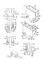
- Figure 1 shows a double bow axillary crutch 10 which includes two tubular bow members 12 having parallel upper portions joined by an arm pad 14 and further connected at an intermediate point by a handle 16.
- the bow members have curved bow sections 18 and parallel lower portions 20 terminating in lower ends 22.
- a footpiece mounting tube 24 is fixed between the parallel sections 20 of the bow members by means of a rivet 26 traversing the footpiece mounting tube and the two bow tubes 12 at an upper point, and by an end cap 30 which receives and interconnects the lower ends 22 of the bow members and the lower end 28 of the foot piece mounting tube 24, all as best understood by reference to Figure 4b.
- the end cap 30 has an upper side 32 in which are defined three substantially cylindrical sockets 34, 36, 38 with their axes mutually parallel and also parallel to the foot piece and bow members of the crutch.
- the central axes of the three sockets lie within a common plane such that the socket 36 is a centre socket disposed between side sockets 34 and 38.
- the cylindrical wall 35 of the centre socket 36 extends downwardly below the bottoms 42 of the side sockets as best seen in Figure 3 and 4b and terminates in a circular bushing 40 which defines a footpiece opening 41 having a diameter somewhat smaller than the inner diameter of the centre socket 36.
- the bottoms 42 of side sockets 34 and 38 are preferably closed.
- the end cap 30 further includes triangular webs 44 extending between each socket bottom 42 and the centre socket wall 35 which define slanting or tapering side edges 46 rising from the bottom centre of the cap 30, i.e. from the level of bushing 40 upwardly towards the sides 48 of the end cap at the laterally outermost point of each socket bottom 42.
- the edges 46 prevent stair edges from catching underneath the squared off transverse lower ends 22 of the bow members.
- a footpiece segment 50 telescopically slides into the footpiece mounting tube 24 and is provided with a locking pin mechanism which includes a pair of spring loaded pins 52 projecting outwardly at diametrically opposed holes in the footpiece tube wall and spring loaded by springs 54.
- the two pins 52 can be manually pushed into the footpiece 50 against springs 54 so as to release and allow sliding movement of the footpiece within the mounting tube 24.
- the footpiece mounting tube 24 is provided with a number of pin holes 56 spaced along the length of tube 24.
- the footpiece locking pins 52 may be released under spring urging into any of the holes 56 so as to interlock the footpiece 50 to the mounting tube 24 at any desired relative extension of the footpiece thereby fixing a desired crutch height.
- the diametrically opposing pins 52 interlock the telescoping tubes 50 and 24 and thereby hold the upper end of the footpiece against wobbling within its mounting tube, particularly in a plan transverse to the orientation of the two pins if the pins fit closely into the openings 56.
- the lower end of the footpiece 50 is supported against wobbling within its mounting tube 24 by the bushing 40 provided in the centre socket 36 of the stair deflecting end cap 30, as illustrated in Figure 4b.
- Figure 4a is rotated 90 degrees about a vertical axis relative to Figure 4b so as to better illustrate the interlocking pins 52 which would be seen end-on without the aforementioned rotation, as will become apparent by inspection of Figure 1.
- the end cap 30 is secured to the lower ends of the bow members by means of two rivets 58 passing through side walls 48 of the end cap and engaging the tube walls of the bow members 20 near their lower ends as best seen in Figure 4b.
- the end cap 30 may be moulded in a plastic material as a single piece.
- a double bow crutch 70 is shown in relevant part to illustrate the provisions of a stair deflecting end cap 72 in a wooden crutch having a one piece footpiece 74 slidable between the adjacent parallel lower ends 76 of the two bow members 75.
- the footpiece 74 is perforated with bolt holes (not shown) at a number of locations spaced along the footpiece 74.
- a retaining bolt 78 extends through the bow member portions 76 and through a selected bolt hold in the footpiece 74, so as to lock together the foot piece and bow members.
- the crutch is adjustable by removing the bolt 78 and sliding the footpiece 74 through the end cap 72 to a desired position and then reinserting the bolt 78 through aligned holes in the footpiece and the bow member portions 76 to thereby fix the footpiece in place.
- the bolt 78 is retained by a winged nut 79.
- the end cap 72 is secured to the bow members 78 by means of two screws 81 threaded through holes 86 in the cap and into the bow members 76.
- the stair deflecting end cap 72 is better seen in perspective view in Figure 6.
- the cap 72 comprises a cap wall defining a rectangular receptacle 80, a cap bottom 82, a central rectangular opening in the bottom communicating into a tubular guide extension 84 of rectangular cross-section.
- the interior dimensions of the receptacle 80 are just slightly greater than the combined width of the two bow members 76 and footpiece 74, while the footpiece guide 84 is dimensioned to fit closely about the cross-section of the footpiece 74 and allow sliding movement of the footpiece through the cap 72.
- Two opposed screw openings 86 are formed in the side walls 84 of the end cap 72 for allowing insertion of the retainer screws 81 through the cap and into threading engagement with the bow members, thus securing the cap to the bow members 76.
- Two co-planar triangular webs 88 extend between the bottom 82 of the cap and each side of the lower footpiece extension 84 of the cap.
- the webs 88 define stair deflecting edges 90 which provide a tapering, gradual transition between the sides 94 of the end cap and the lower edge 92 of the footpiece extension.
- the slanting edges 90 prevent staircase edges from being caught in the two corners defined between the horizontal bottom wall 82 and the vertical extension wall 84 of the cap 72.
- Figures 7 and 8 illustrate an alternate end cap 100 which is similar to that of Figure 6 as indicated by common numbering of common elements, but is modified by provision of partitions 102 which divide the single receptacle 80 of the Figure 6 end cap into two side sockets 104, each of which receives the lower end of a bow member 75 of the crutch, and a central tubular footpiece passage 106 of rectangular cross-section through which slides the footpiece 74 for adjusting the crutch height.
- Figure 9 illustrates an alternate manner of providing stair deflecting surfaces on a wooden crutch which is only shown in relevant part and comprises bow members 112 between which is slidable a footpiece 114. Both the bow member and the footpiece are of rectangular cross-section.
- a retaining band 116 encompasses the bow members and footpiece to retain these three pieces in parallel adjacent relationship, while allowing the footpiece 114 to slide freely intermediate the bow members 112.
- the footpiece 114 is provided with conventional spaced bolt hole openings (not shown) in a manner similar to that of crutch of Figure 5, and is provided with two retaining screws 118 which extend through the retaining band 116 and are threaded into the bow members 112.
- the footpiece 114 is adjustably interlocked to the bow members against relative sliding movement by a transverse retaining bolt not shown in Figure 9 but similar to bolt 78 and nut 79 of Figure 5.
- the lower ends of the bow members 112 are arcuately curved to provide stair deflecting surfaces 122 which taper from the sides 124 of the two bow members towards the sides 126 of the foot piece 114.
- the stair deflecting surfaces 122 thus provide a gradual flaring of the crutch profile from the relatively narrow footpiece to the wider bow members, thus preventing staircase edges from wedging into any corners which would otherwise be defined by a stepped, abrupt transition between squared off lower ends of the bow members and the footpiece 114.
- the curved shaping of the bow member ends 122 serves a purpose similar to the slanting edges 90 of the end caps of Figures 5 - 8 but in a more economical manner which may be desirable in lower cost wooden crutches of basic construction.
Landscapes
- Health & Medical Sciences (AREA)
- Epidemiology (AREA)
- Pain & Pain Management (AREA)
- Physical Education & Sports Medicine (AREA)
- Rehabilitation Therapy (AREA)
- Life Sciences & Earth Sciences (AREA)
- Animal Behavior & Ethology (AREA)
- General Health & Medical Sciences (AREA)
- Public Health (AREA)
- Veterinary Medicine (AREA)
- Rehabilitation Tools (AREA)
Applications Claiming Priority (2)
| Application Number | Priority Date | Filing Date | Title |
|---|---|---|---|
| US06/800,697 US4872469A (en) | 1985-11-22 | 1985-11-22 | Crutch with stair deflector |
| US800697 | 1985-11-22 |
Publications (2)
| Publication Number | Publication Date |
|---|---|
| EP0224975A2 true EP0224975A2 (de) | 1987-06-10 |
| EP0224975A3 EP0224975A3 (de) | 1989-04-19 |
Family
ID=25179132
Family Applications (1)
| Application Number | Title | Priority Date | Filing Date |
|---|---|---|---|
| EP86302739A Withdrawn EP0224975A3 (de) | 1985-11-22 | 1986-04-14 | Krücke mit Einrichtung zum Vermeiden des Hängenbleibens an Treppenkanten |
Country Status (3)
| Country | Link |
|---|---|
| US (1) | US4872469A (de) |
| EP (1) | EP0224975A3 (de) |
| JP (1) | JPS62127052A (de) |
Cited By (3)
| Publication number | Priority date | Publication date | Assignee | Title |
|---|---|---|---|---|
| GB2198645A (en) * | 1986-12-22 | 1988-06-22 | Wang Lee Mei Chin | Height adjustable walking aid |
| EP0641554A3 (de) * | 1993-05-10 | 1995-08-02 | Cho Kyong Ok | Orthopädie - technische Verbesserung bei Aluminium Achselkrücken. |
| CN111973408A (zh) * | 2020-09-03 | 2020-11-24 | 合肥工业大学 | 一种新型医用腋下拐杖 |
Families Citing this family (11)
| Publication number | Priority date | Publication date | Assignee | Title |
|---|---|---|---|---|
| US6315252B1 (en) * | 1997-10-17 | 2001-11-13 | Jefrey S. Schultz | Removably mounted computer stand for automobiles and the like |
| KR200317554Y1 (ko) * | 1998-09-11 | 2003-10-17 | 조경일 | 높이조절이용이한목발 |
| US20030075209A1 (en) * | 1999-09-07 | 2003-04-24 | Kyungil-Cho | Bolt-type adjustable crutch |
| US20030084932A1 (en) * | 1999-09-07 | 2003-05-08 | Kyungil-Cho | Bolt-type adjustable crutch |
| US6691270B2 (en) * | 2000-12-22 | 2004-02-10 | Arm Limited | Integrated circuit and method of operation of such a circuit employing serial test scan chains |
| KR100437481B1 (ko) * | 2001-06-28 | 2004-06-25 | 삼부크러치주식회사 | 칼라강판을 사용한 목발 |
| US6920834B1 (en) * | 2002-02-11 | 2005-07-26 | John A. Pehta | Tubular table height adjuster |
| US7624862B1 (en) * | 2004-03-10 | 2009-12-01 | Patrick Pleggenkuhle | Chainsaw carrier |
| US20060118154A1 (en) * | 2004-11-24 | 2006-06-08 | Medline Industries, Inc. | Crutches that convert into canes and methods for conversion of same |
| CN218505772U (zh) * | 2022-08-22 | 2023-02-21 | 富泰京精密电子(烟台)有限公司 | 缓冲吸能支架 |
| USD1096126S1 (en) * | 2024-08-15 | 2025-10-07 | Zhongshan Bliss Medical Instrument Co., Ltd | Crutch |
Family Cites Families (15)
| Publication number | Priority date | Publication date | Assignee | Title |
|---|---|---|---|---|
| US32815A (en) * | 1861-07-16 | Island | ||
| US683568A (en) * | 1901-06-25 | 1901-10-01 | Allen H | Crutch. |
| US1035760A (en) * | 1911-10-24 | 1912-08-13 | Samuel W Walton | Crutch. |
| AT72148B (de) * | 1915-07-26 | 1916-07-25 | Georg Guttenbrunner | Krückenfuß. |
| GB115327A (en) * | 1917-06-27 | 1918-05-09 | Arthur Edward Walby | An Adjustable Extension Crutch. |
| GB124911A (en) * | 1918-04-13 | 1919-04-10 | Katherine Basler Yates | Adjustable Crutch for Invalids, Cripples and the like. |
| US1505081A (en) * | 1923-01-16 | 1924-08-19 | Otto H Arndt | Crutch |
| FR695987A (fr) * | 1930-05-19 | 1930-12-24 | Poyet Freres | Béquille orthopédique à hauteur variable |
| GB1104255A (en) * | 1964-11-03 | 1968-02-21 | Doherty Sons Ltd Edward | Crutches |
| GB1234053A (de) * | 1968-09-27 | 1971-06-03 | ||
| JPS5223191U (de) * | 1975-08-05 | 1977-02-18 | ||
| USRE32815E (en) | 1983-01-03 | 1989-01-03 | Guardian Products, Inc. | Height adjustable crutch |
| US4509741A (en) * | 1983-01-03 | 1985-04-09 | Guardian Products Company, Inc. | Height adjustable crutch |
| US4733682A (en) * | 1986-12-16 | 1988-03-29 | Guardian Products, Inc. | Tubular crutch construction |
| JPH022485U (de) * | 1988-06-17 | 1990-01-09 |
-
1985
- 1985-11-22 US US06/800,697 patent/US4872469A/en not_active Expired - Lifetime
-
1986
- 1986-04-14 EP EP86302739A patent/EP0224975A3/de not_active Withdrawn
- 1986-07-01 JP JP61154963A patent/JPS62127052A/ja active Granted
Cited By (4)
| Publication number | Priority date | Publication date | Assignee | Title |
|---|---|---|---|---|
| GB2198645A (en) * | 1986-12-22 | 1988-06-22 | Wang Lee Mei Chin | Height adjustable walking aid |
| GB2198645B (en) * | 1986-12-22 | 1990-08-08 | Wang Lee Mei Chin | Height adjustable walking aid |
| EP0641554A3 (de) * | 1993-05-10 | 1995-08-02 | Cho Kyong Ok | Orthopädie - technische Verbesserung bei Aluminium Achselkrücken. |
| CN111973408A (zh) * | 2020-09-03 | 2020-11-24 | 合肥工业大学 | 一种新型医用腋下拐杖 |
Also Published As
| Publication number | Publication date |
|---|---|
| US4872469A (en) | 1989-10-10 |
| JPH0257427B2 (de) | 1990-12-04 |
| JPS62127052A (ja) | 1987-06-09 |
| EP0224975A3 (de) | 1989-04-19 |
Similar Documents
| Publication | Publication Date | Title |
|---|---|---|
| EP0224975A2 (de) | Krücke mit Einrichtung zum Vermeiden des Hängenbleibens an Treppenkanten | |
| US5038430A (en) | Attaching means for bed cross brace | |
| CA2208993C (en) | Composite base assembly for cane having fifth leg | |
| CA2458152C (en) | Assist handle assembly for beds | |
| US5894614A (en) | Bed rail center support system | |
| US8025071B2 (en) | Bases and braces for support poles, such as poles for pavilions and umbrellas | |
| US6079894A (en) | Integral snap button and anti-rattle member | |
| US6173660B1 (en) | Bench folding leg and brace structure | |
| CA2662513C (en) | Clamp assembly for use with adjustable bed rail cross support members | |
| US4721125A (en) | Height adjustable crutch | |
| DE8530227U1 (de) | Dreh- und höhenverstellbarer Einsäulen-Präsentierständer | |
| EP1106161A2 (de) | Selbsttragender Gehstock oder Krücke | |
| EP0005544B1 (de) | Vorrichtung zum lösbaren Verankern einer Warenablage an einer Säule eines Inneneinrichtungssystems | |
| US4852597A (en) | Crutch design | |
| KR200317554Y1 (ko) | 높이조절이용이한목발 | |
| GB2267030A (en) | Support for adjusting the height of furniture | |
| KR940005170Y1 (ko) | 과수용 사다리의 받침 지주높이조절 장치 | |
| KR100395628B1 (ko) | 외발 사다리 | |
| JP3018561U (ja) | 傘立て | |
| US12330168B2 (en) | Nestable highbanker | |
| KR900009956Y1 (ko) | 선풍기의 높이 조절용 파이프 가이드 | |
| KR890001184Y1 (ko) | 자전거 안장의 높이조절 장치 | |
| KR100428486B1 (ko) | 피엘 램프용 교체기구 | |
| JP2892182B2 (ja) | 運動用装置 | |
| KR890004354Y1 (ko) | 모니터의 화면 높이 및 각도 조절장치 |
Legal Events
| Date | Code | Title | Description |
|---|---|---|---|
| PUAI | Public reference made under article 153(3) epc to a published international application that has entered the european phase |
Free format text: ORIGINAL CODE: 0009012 |
|
| AK | Designated contracting states |
Kind code of ref document: A2 Designated state(s): DE FR GB IT SE |
|
| PUAL | Search report despatched |
Free format text: ORIGINAL CODE: 0009013 |
|
| AK | Designated contracting states |
Kind code of ref document: A3 Designated state(s): DE FR GB IT SE |
|
| STAA | Information on the status of an ep patent application or granted ep patent |
Free format text: STATUS: THE APPLICATION IS DEEMED TO BE WITHDRAWN |
|
| 18D | Application deemed to be withdrawn |
Effective date: 19890503 |
|
| RIN1 | Information on inventor provided before grant (corrected) |
Inventor name: SCHULTZ, JIM. R. |