EP0224543B1 - Gerät zur anzeige des schwankens - Google Patents
Gerät zur anzeige des schwankens Download PDFInfo
- Publication number
- EP0224543B1 EP0224543B1 EP86903490A EP86903490A EP0224543B1 EP 0224543 B1 EP0224543 B1 EP 0224543B1 EP 86903490 A EP86903490 A EP 86903490A EP 86903490 A EP86903490 A EP 86903490A EP 0224543 B1 EP0224543 B1 EP 0224543B1
- Authority
- EP
- European Patent Office
- Prior art keywords
- subject
- ultrasound
- transmitter
- sway
- pulse
- Prior art date
- Legal status (The legal status is an assumption and is not a legal conclusion. Google has not performed a legal analysis and makes no representation as to the accuracy of the status listed.)
- Expired - Lifetime
Links
- 238000002604 ultrasonography Methods 0.000 claims abstract description 21
- 238000012806 monitoring device Methods 0.000 claims description 4
- 230000033001 locomotion Effects 0.000 abstract description 9
- 238000000034 method Methods 0.000 description 7
- 238000005259 measurement Methods 0.000 description 5
- 238000012544 monitoring process Methods 0.000 description 4
- 230000005540 biological transmission Effects 0.000 description 3
- 238000010586 diagram Methods 0.000 description 3
- 230000003750 conditioning effect Effects 0.000 description 2
- 230000000857 drug effect Effects 0.000 description 2
- 230000010004 neural pathway Effects 0.000 description 2
- 208000014644 Brain disease Diseases 0.000 description 1
- 206010012289 Dementia Diseases 0.000 description 1
- 230000004913 activation Effects 0.000 description 1
- 230000032683 aging Effects 0.000 description 1
- 238000004458 analytical method Methods 0.000 description 1
- 238000003491 array Methods 0.000 description 1
- 210000000133 brain stem Anatomy 0.000 description 1
- 210000003169 central nervous system Anatomy 0.000 description 1
- 210000001638 cerebellum Anatomy 0.000 description 1
- 230000003111 delayed effect Effects 0.000 description 1
- 230000001419 dependent effect Effects 0.000 description 1
- 238000001514 detection method Methods 0.000 description 1
- 230000009977 dual effect Effects 0.000 description 1
- 230000000694 effects Effects 0.000 description 1
- 238000011156 evaluation Methods 0.000 description 1
- 230000004424 eye movement Effects 0.000 description 1
- 230000001815 facial effect Effects 0.000 description 1
- 238000012423 maintenance Methods 0.000 description 1
- 210000001259 mesencephalon Anatomy 0.000 description 1
- 230000001144 postural effect Effects 0.000 description 1
- 230000009023 proprioceptive sensation Effects 0.000 description 1
- 229940001470 psychoactive drug Drugs 0.000 description 1
- 230000001003 psychopharmacologic effect Effects 0.000 description 1
- 239000004089 psychotropic agent Substances 0.000 description 1
- 230000001105 regulatory effect Effects 0.000 description 1
- 230000000717 retained effect Effects 0.000 description 1
- 230000001953 sensory effect Effects 0.000 description 1
- 210000000278 spinal cord Anatomy 0.000 description 1
- 230000001720 vestibular Effects 0.000 description 1
Images

Classifications
-
- A—HUMAN NECESSITIES
- A61—MEDICAL OR VETERINARY SCIENCE; HYGIENE
- A61B—DIAGNOSIS; SURGERY; IDENTIFICATION
- A61B5/00—Measuring for diagnostic purposes; Identification of persons
- A61B5/103—Measuring devices for testing the shape, pattern, colour, size or movement of the body or parts thereof, for diagnostic purposes
- A61B5/11—Measuring movement of the entire body or parts thereof, e.g. head or hand tremor or mobility of a limb
-
- A—HUMAN NECESSITIES
- A61—MEDICAL OR VETERINARY SCIENCE; HYGIENE
- A61B—DIAGNOSIS; SURGERY; IDENTIFICATION
- A61B5/00—Measuring for diagnostic purposes; Identification of persons
- A61B5/40—Detecting, measuring or recording for evaluating the nervous system
- A61B5/4005—Detecting, measuring or recording for evaluating the nervous system for evaluating the sensory system
- A61B5/4023—Evaluating sense of balance
-
- A—HUMAN NECESSITIES
- A61—MEDICAL OR VETERINARY SCIENCE; HYGIENE
- A61B—DIAGNOSIS; SURGERY; IDENTIFICATION
- A61B8/00—Diagnosis using ultrasonic, sonic or infrasonic waves
- A61B8/48—Diagnostic techniques
- A61B8/488—Diagnostic techniques involving Doppler signals
Definitions
- This invention relates to a sway detecting and monitoring apparatus, particularly to such an apparatus for use in assessing drug effects on human volunteers or patients.
- the upright stance in the human is an unstable position and therefore always accompanied by involuntary motion.
- This postural sway is a reflection of the noise and regulatory activity of the several control loops involved in the maintenance of balance.
- the principal sensory systems involved in this are proprioception, the vestibular system and vision, and the afferent neuronal pathways within the central nervous system.
- the afferent and efferent neuronal pathways involve spinal cord, brainstem, cerebellum, midbrain and sensorimotor cortex. Interference in any of these systems can therefore affect balance, and body sway is often used an an index of psychotropic drug activity in normal subjects. It has also been proposed as an objective index of the extent of progression of, and drug effect on, diffuse brain disease such as dementia [Visser, H. (1983) Age and Ageing, 12, 296-301].
- the present invention provides an ultrasound technique for measuring and monitoring body sway.
- a sway detecting and monitoring device comprising
- 'ultrasound beam' as used herein is intended to describe a series of rapid pulses of ultrasound frequency, rather than a continuous emission of ultrasound, and detection of the swaying movement is based on the principle that the time taken for the ultrasonic pulses to travel from the transmitter and return to the receiver after reflection from the subject will vary as the subject sways.
- each transmitter/receiver pair is in the form of a single combined unit commonly known as an ultrasonic 'sensor'.
- the transmitter and receiver are associated with a transducer such that during transmission, the transducer acts as an emitter of ultrasonic pulses.
- the tranducer is switched to operate with the receiver (the transducer being used as a microphone); after receiving reflected ultrasound, the transducer is switched to operate with the transmitter again, and so on.
- the sensors are used, each set at right angles to the other.
- the sensors may be placed at right- angles, suitably some 700 mm from the body and at a height of approximately 1300 mm. This arangement permits recording of both lateral (sideways) and saggital (front/rear) components of sway).
- the frequencies emitted by the transmitters are in the range 50-70 KHz, either as a 'chirp' (i.e. a burst of pulses comprising several frequencies), or as a pulse of a single frequency.
- each transmitter is activated (i.e. caused to emit an ultrasonic pulse or burst of pulses, typically of ca. 1 millisecond duration) approximately 15 times per second. It is desirable that each transmitter be activated alternately in order to avoid false signals by reflection of ultrasound generated by the other transmitter.
- Outputs from the ranging means may be digital, i.e. pulses whose duration is proportional to the distance swayed, or made available as analogue voltages.
- the deviation of the subject from a fixed 'zero' position may be continuously monitored.
- the delay between the first and second timing signals is compared with the delay measured when the subject is at a predetermined zero position.
- the first timing signal is electronically delayed until it coincides with the second timing signal and the ranging means is adjusted to give a nil output at this coincident position.
- the swaying of the subject thus causes the second timing signal to be advanced or retarded relative to the first timing signal.
- the output from the ranging means is related to the advancement or retardation of the second timing signal and is thus directly proportional to the distance of sway from the zero position.
- the deviation of the subject from each sensor is continuously monitored.
- the delay between the first and second timing signals may suitably be analysed by a microcomputer and a 'sway index' may be generated which quantifies the swaying movements made by the subject with respect to each sensor over a period of time.
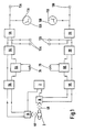
- two ultrasonic sensors 1A for monitoring saggital sway and 1 B (for monitoring lateral sway) are arranged at right angles at an appropriate distance from a human subject 2.
- Suitable sensors are commercially available, for example from Polaroid U.K. Ltd.
- the sensors 1A and 1B are controlled by an alternate drive clock 3 by means of which they may be activated alternately, each sensor being activated approximately 15 times per second.
- the sensors 1A and 1B produce a burst of pulses (represented by 'waves' 4A and 4B) at ultrasound frequencies of 50, 53, 57 and 60 KHz.
- the duration of the pulses produced by each sensor is approximately 1 millisecond.
- a 'sound transmitted' signal pulse is sent from the sensor (1A or 1B) responsible for the transmission to its respective 'sensor interface' (5A or 5B), and the sensor (1A or 1 B) is then temporarily switched to become a sensitive receiver using the transducer as a microphone.
- a logic pulse is generated and fed to the corresponding sensor interface 5A or 5B.
- leading edge of such an 'echo-received' signal pulse is used, in conjunction with the leading edge of the 'sound-transmitted' signal pulse, to derive from each sensor interface, 5A and 5B, an output signal proportional to the distance between the corresponding sensor, 1A or 1B, and the subject 2.
- variable delay circuits 6A and 6B are adjusted by means of a simple zero control, 7A or 7B, until the 'sound-transmitted' output signal from each sensor interface 5A and 5B is sufficiently retarded for the corresponding 'echo-received' signal to be received simultaneously by respective differential time comparators 8A and 8B. At that point no output pulses are emitted from the differential time comparators 8A and 8B.
- the differential time comparators 8A and 8B are connected to voltage converters 9A and 9B and thus, in practice, the zero position may be readily defined by adjusting the zero controls 7A and 7B until respective panel meters 10A and 10B show no deflection from median positions 11A and 11 B.
- a swaying subject 2 will then cause the 'echo' signal to arrive early (when subject 2 moves towards the sensor 1A or 18) or late (when subject 2 moves away from sensor 1A or 1 B) with respect to the 'sound-transmitted' signal.
- the result of such swaying movement is to cause the differential time caparator 8A or 8B to emit pulses, the width of which is proportional to the distance moved by the subject 2, from the zero position, away from or towards the sensor 1A or 1B.
- the digital outputs 12A and 12B from the differential time comparators 8A and 8B may be fed directly to a computer or converted by means of corresponding voltage converters 9A and 9B to output, at points 13A and 13B, analogue voltages that vary linearly with sensor-to-subject distance. These can be recorded independently on a dual channel Yt chart recorder or combined on an X-Y plotter. Such recordings can be immediately visually interpreted for frequency, amplitude of sway and, if desired, recorded on magnetic tape to enable later replay into a computer. Provision of a computer system is advantageous for signal analysis by such methods as the Fourier Transform or 'line-length' evaluation (i.e. determination of the total length of a trace).
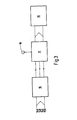
- FIG 2 the arrangement of components is the same as shown in Figure 1 as hereinbefore described, but in addition terminals 14A and 14B and 15A and 15B are provided. From these terminals the output signals from the sensor interfaces 5A and 5B may be fed into a microcomputer programmed to record and display data related to the swaying movements of the subject over any given time period.
- the variable delay circuits 6A and 6B, zero controls.7A and 7B, and other components 8A-13A and 8B-13B are optional, but are usefully retained so that, if desired, a chart recorder may be used simultaneously with the microcomputer.
- the signals from the terminals 14A, 14B and 15A, 15B may be fed into a signal conditioning unit 16 which converts each output into a pulse, the duration of which varies with the distance of the subject from the sensors 1A and 1B ( Figure 2).
- the pulses from the signal conditioning unit 16 then pass into a microcomputer 17 which may, for example, be programmed to generate a 'sway index'.
- the sway index (S) is a numerical value which gives a measure of the swaying motions made by the subject 2 over a given time period and two separate figures-one for lateral sway and one for sagittal sway - are computed.
- the microcomputer 17 is programmed to calculate S according to the equation: where n is the number of ultrasonic pulses per second generated by the transmitters 1A and 1 B, and X is the time between the i th transmitted and received pulse.
- the measurement of the sway index may be commenced by manually pressing a start button 18 and at the end of 1 minute, the values of S obtained for both sagittal and lateral sway are displayed on the LCD charter display 19. It will be appreciated that sway index data may be generated in this way without any need for the subject to stand at a pre-determined zero position provided he or she stands within the beam path and within the ranging capabilities of the instrument.
- the computer is programmed to detect any movement out of the beam path and measurement of the sway index cannot be started or will be discontinued if that occurs.
- the application of ultrasound to the measurement of body sway by means of the present invention provides a compact, portable, inexpensive, objective, non-contact method well suited to use in psychopharmacological studies both in normal healthy volunteers and in patients.
Landscapes
- Health & Medical Sciences (AREA)
- Life Sciences & Earth Sciences (AREA)
- Molecular Biology (AREA)
- Surgery (AREA)
- Physics & Mathematics (AREA)
- Veterinary Medicine (AREA)
- Biophysics (AREA)
- Pathology (AREA)
- Engineering & Computer Science (AREA)
- Biomedical Technology (AREA)
- Heart & Thoracic Surgery (AREA)
- Animal Behavior & Ethology (AREA)
- Public Health (AREA)
- General Health & Medical Sciences (AREA)
- Medical Informatics (AREA)
- Physiology (AREA)
- Neurology (AREA)
- Neurosurgery (AREA)
- Dentistry (AREA)
- Oral & Maxillofacial Surgery (AREA)
- Nuclear Medicine, Radiotherapy & Molecular Imaging (AREA)
- Radiology & Medical Imaging (AREA)
- Measurement Of Velocity Or Position Using Acoustic Or Ultrasonic Waves (AREA)
- Measurement Of The Respiration, Hearing Ability, Form, And Blood Characteristics Of Living Organisms (AREA)
Claims (8)

Applications Claiming Priority (4)
| Application Number | Priority Date | Filing Date | Title |
|---|---|---|---|
| GB8513867 | 1985-06-01 | ||
| GB858513867A GB8513867D0 (en) | 1985-06-01 | 1985-06-01 | Apparatus |
| GB858522170A GB8522170D0 (en) | 1985-09-06 | 1985-09-06 | Apparatus |
| GB8522170 | 1985-09-06 |
Publications (2)
| Publication Number | Publication Date |
|---|---|
| EP0224543A1 EP0224543A1 (de) | 1987-06-10 |
| EP0224543B1 true EP0224543B1 (de) | 1990-08-16 |
Family
ID=26289316
Family Applications (1)
| Application Number | Title | Priority Date | Filing Date |
|---|---|---|---|
| EP86903490A Expired - Lifetime EP0224543B1 (de) | 1985-06-01 | 1986-05-30 | Gerät zur anzeige des schwankens |
Country Status (3)
| Country | Link |
|---|---|
| EP (1) | EP0224543B1 (de) |
| DE (1) | DE3673499D1 (de) |
| WO (1) | WO1986006949A1 (de) |
Family Cites Families (5)
| Publication number | Priority date | Publication date | Assignee | Title |
|---|---|---|---|---|
| DK138861B (da) * | 1972-08-28 | 1978-11-06 | Akad Tekn Videnskaber | Apparat til ultralydundersøgelse. |
| GB1450838A (en) * | 1973-05-10 | 1976-09-29 | Hitachi Shipbuilding Eng Co | Device for determining the three-dimensional co-ordinates of a point in an article |
| NL8102059A (nl) * | 1981-04-27 | 1982-11-16 | Univ Leiden | Inrichting en werkwijze voor het kwantitatief beoordelen van onwillekeurige lichaamsbewegingen. |
| FR2571955A1 (fr) * | 1984-10-24 | 1986-04-25 | Compact Ind | Dispositif pour la surveillance a distance de la respiration d'une personne alitee |
| AT384544B (de) * | 1984-12-11 | 1987-11-25 | Siemens Ag Oesterreich | Verfahren zur bestimmung der beweglichkeit von koerperteilen |
-
1986
- 1986-05-30 EP EP86903490A patent/EP0224543B1/de not_active Expired - Lifetime
- 1986-05-30 WO PCT/GB1986/000302 patent/WO1986006949A1/en not_active Ceased
- 1986-05-30 DE DE8686903490T patent/DE3673499D1/de not_active Expired - Fee Related
Also Published As
| Publication number | Publication date |
|---|---|
| DE3673499D1 (de) | 1990-09-20 |
| WO1986006949A1 (en) | 1986-12-04 |
| EP0224543A1 (de) | 1987-06-10 |
Similar Documents
| Publication | Publication Date | Title |
|---|---|---|
| EP0747010B1 (de) | Kontinuierliche Anzeige von Blutströmungsinformationen | |
| US5564423A (en) | Ultrasonic measurement system for the determination of bone density and structure | |
| JP4558288B2 (ja) | 弱い生理的信号を検出する生理監視システム | |
| US5143087A (en) | Analysis and treatment of swallowing dysfunction | |
| US4660564A (en) | Apparatus for measuring pulsetile part-structures within a living body | |
| EP3493745B1 (de) | Ultraschallblutflussüberwachung | |
| EP0231260A1 (de) | Gerät zur unblutigen bestimmung des herzschlagvolumens | |
| US20120095306A1 (en) | Sensing gas bubbles in a living body | |
| WO2003088838A1 (en) | Methods and systems for distal recording of phonocardiographic signals | |
| JP7001244B1 (ja) | 非接触生体信号検出装置 | |
| JPS5849137A (ja) | 超音波血流測定装置 | |
| US9380994B2 (en) | Ultrasonic diagnostic apparatus | |
| Jeger-Madiot et al. | Non-contact and through-clothing measurement of the heart rate using ultrasound vibrocardiography | |
| US5879293A (en) | Non-invasive uterine activity sensor | |
| US4475397A (en) | Method and means for attaining ultrasonic attenuation by vector sample averaging | |
| EP0224543B1 (de) | Gerät zur anzeige des schwankens | |
| US5313944A (en) | Measurement of internal body structure during biomagnetometry | |
| AU7256896A (en) | Apparatus and method for measuring an induced perturbation to determine a physical condition of the human arterial system | |
| US20100312110A1 (en) | Ultrasonograph | |
| US4463592A (en) | Method of determining operating characteristics of ultrasonic scanning systems | |
| JPH05228121A (ja) | 人体情報センサ | |
| JP3091269B2 (ja) | 表面血流測定装置 | |
| JPH09103430A (ja) | 超音波骨分析装置及び身体の部分を検知する方法 | |
| JP2955630B1 (ja) | 心機能検査装置 | |
| JPS6129735B2 (de) |
Legal Events
| Date | Code | Title | Description |
|---|---|---|---|
| PUAI | Public reference made under article 153(3) epc to a published international application that has entered the european phase |
Free format text: ORIGINAL CODE: 0009012 |
|
| 17P | Request for examination filed |
Effective date: 19870216 |
|
| AK | Designated contracting states |
Kind code of ref document: A1 Designated state(s): BE CH DE FR GB IT LI NL |
|
| 17Q | First examination report despatched |
Effective date: 19881114 |
|
| GRAA | (expected) grant |
Free format text: ORIGINAL CODE: 0009210 |
|
| AK | Designated contracting states |
Kind code of ref document: B1 Designated state(s): BE CH DE FR GB IT LI NL |
|
| REF | Corresponds to: |
Ref document number: 3673499 Country of ref document: DE Date of ref document: 19900920 |
|
| ITF | It: translation for a ep patent filed | ||
| ET | Fr: translation filed | ||
| PGFP | Annual fee paid to national office [announced via postgrant information from national office to epo] |
Ref country code: GB Payment date: 19910520 Year of fee payment: 6 |
|
| PGFP | Annual fee paid to national office [announced via postgrant information from national office to epo] |
Ref country code: FR Payment date: 19910522 Year of fee payment: 6 |
|
| ITTA | It: last paid annual fee | ||
| PGFP | Annual fee paid to national office [announced via postgrant information from national office to epo] |
Ref country code: NL Payment date: 19910531 Year of fee payment: 6 |
|
| PGFP | Annual fee paid to national office [announced via postgrant information from national office to epo] |
Ref country code: CH Payment date: 19910606 Year of fee payment: 6 |
|
| PLBE | No opposition filed within time limit |
Free format text: ORIGINAL CODE: 0009261 |
|
| STAA | Information on the status of an ep patent application or granted ep patent |
Free format text: STATUS: NO OPPOSITION FILED WITHIN TIME LIMIT |
|
| PGFP | Annual fee paid to national office [announced via postgrant information from national office to epo] |
Ref country code: DE Payment date: 19910628 Year of fee payment: 6 |
|
| PGFP | Annual fee paid to national office [announced via postgrant information from national office to epo] |
Ref country code: BE Payment date: 19910705 Year of fee payment: 6 |
|
| 26N | No opposition filed | ||
| PG25 | Lapsed in a contracting state [announced via postgrant information from national office to epo] |
Ref country code: GB Effective date: 19920530 |
|
| PG25 | Lapsed in a contracting state [announced via postgrant information from national office to epo] |
Ref country code: LI Effective date: 19920531 Ref country code: CH Effective date: 19920531 Ref country code: BE Effective date: 19920531 |
|
| BERE | Be: lapsed |
Owner name: BEECHAM GROUP P.L.C. Effective date: 19920531 |
|
| PG25 | Lapsed in a contracting state [announced via postgrant information from national office to epo] |
Ref country code: NL Effective date: 19921201 |
|
| NLV4 | Nl: lapsed or anulled due to non-payment of the annual fee | ||
| GBPC | Gb: european patent ceased through non-payment of renewal fee |
Effective date: 19920530 |
|
| PG25 | Lapsed in a contracting state [announced via postgrant information from national office to epo] |
Ref country code: FR Effective date: 19930129 |
|
| REG | Reference to a national code |
Ref country code: CH Ref legal event code: PL |
|
| PG25 | Lapsed in a contracting state [announced via postgrant information from national office to epo] |
Ref country code: DE Effective date: 19930202 |
|
| PG25 | Lapsed in a contracting state [announced via postgrant information from national office to epo] |
Ref country code: IT Free format text: LAPSE BECAUSE OF NON-PAYMENT OF DUE FEES Effective date: 20050530 |