EP0224429B1 - Gas turbine engine augmentor - Google Patents
Gas turbine engine augmentor Download PDFInfo
- Publication number
- EP0224429B1 EP0224429B1 EP86630174A EP86630174A EP0224429B1 EP 0224429 B1 EP0224429 B1 EP 0224429B1 EP 86630174 A EP86630174 A EP 86630174A EP 86630174 A EP86630174 A EP 86630174A EP 0224429 B1 EP0224429 B1 EP 0224429B1
- Authority
- EP
- European Patent Office
- Prior art keywords
- pilot section
- aperture
- flameholder
- adjacent
- shaped
- Prior art date
- Legal status (The legal status is an assumption and is not a legal conclusion. Google has not performed a legal analysis and makes no representation as to the accuracy of the status listed.)
- Expired - Lifetime
Links
Images

Classifications
-
- F—MECHANICAL ENGINEERING; LIGHTING; HEATING; WEAPONS; BLASTING
- F02—COMBUSTION ENGINES; HOT-GAS OR COMBUSTION-PRODUCT ENGINE PLANTS
- F02C—GAS-TURBINE PLANTS; AIR INTAKES FOR JET-PROPULSION PLANTS; CONTROLLING FUEL SUPPLY IN AIR-BREATHING JET-PROPULSION PLANTS
- F02C1/00—Gas-turbine plants characterised by the use of hot gases or unheated pressurised gases, as the working fluid
-
- F—MECHANICAL ENGINEERING; LIGHTING; HEATING; WEAPONS; BLASTING
- F23—COMBUSTION APPARATUS; COMBUSTION PROCESSES
- F23R—GENERATING COMBUSTION PRODUCTS OF HIGH PRESSURE OR HIGH VELOCITY, e.g. GAS-TURBINE COMBUSTION CHAMBERS
- F23R3/00—Continuous combustion chambers using liquid or gaseous fuel
- F23R3/02—Continuous combustion chambers using liquid or gaseous fuel characterised by the air-flow or gas-flow configuration
- F23R3/16—Continuous combustion chambers using liquid or gaseous fuel characterised by the air-flow or gas-flow configuration with devices inside the flame tube or the combustion chamber to influence the air or gas flow
- F23R3/18—Flame stabilising means, e.g. flame holders for after-burners of jet-propulsion plants
Definitions
- This invention relates to gas turbine power plants with augmentors and more particularly to means for improving the ignition and stabilization characteristics of the augmentor.
- the augmentor comprises a well known flameholder consisting of a pilot section centrally supported in the housing of the augmentor and carries a plurality of radially extending gutters.
- a plurality of sprayrings upstream of the flameholder serves to judiciously inject fuel in the engine's exhaust to be entrained in and ignited in the aerodynamic wake of the flameholder.
- the pilot section is designed to provide a recirculation zone to stabilize the burning characteristics of the fuel so as to sustain combustion and to propagate the combustion around the perimeter of the flameholder.
- the augmentor should be actuated at any time within the flight envelope for the aircraft's mission. It has been known that under certain aircraft operating conditions ignition and/or sustained operation has not been successful.
- the typical pilot section of the augmentor is either domed or "V" shaped and the apex faces the fuel being injected by the sprayring.
- a portion of the fuei/air mixture migrates rearwardly relative to the flow of the engine's exhaust and recirculates inside the pilot section.
- the fuel entrained air is brought in close proximity to the igniter mounted in the pilot section. Unless the fuel/air mixture is within the proper proportions combustion will not ensue. It has been found that the mixture in the heretofore known designs has often been either too lean or too rich for ignition to ensue.
- a flameholder of the type according to the precharacterizing portion of independent claim 1 is disclosed in FR-A 1 199 822.
- a plurality of apertures are formed in the wall of the flameholder pilot section to admit additional fuel entrained air into the primary wake of the flameholder to thereby improve the stability of the flame which attaches to the flameholder aft end. Improvement of the ignition characteristics is not contemplated in FR-A 1 199 822.
- the object of the invention is to provide a flameholder having improved ignition and stability characteristics of the pilot section in the augmentor of a gas turbine engine. This is achieved by the features recited in the characterizing portion of independent claim 1.
- pilot section we have found that we can obviate the fuel/air mixture problem in the pilot section by lecating an opening or slot for discretely flowing the fuel entrained air into the pilot section at a predetermined location and orientation relative to the igniter.
- the opening is located downstream of the leading edge of the flameholder but in proximity thereto.
- the opening is oriented so that its plane is in coincidence with the walls of the opening and is perpendicular to the engine centerline such that the flow admitted into the pilot section is tangential to the inner wall of the apex of the dome and spaced from the igniter so that the fuel/air mixture passes in proximity thereto.
- Tests have shown that a pilot section incorporating this invention forms a small recirculating zone adjacent the igniter, has proven to provide efficacious ignition characteristics and can accommodate operation over a much broader range of fuel-air mixture ratios at all operating conditions.
- An additional advantageous feature is to further improve the overall stability characteristics by creating the circulating vortices described in the paragraphs above around the full circumference of the pilot section. This can be achieved by locating openings as described above around the circumference of the pilot section in a plane perpendicular to the centerline of the pilot section. The openings are oriented such that the flow into the pilot section is introduced tangentially to the inside surface of the leading edge.
- the augmentor incorporated a shroud surrounding the pilot section designed to profile the flow to achieve an improved aerodynamic recirculation zone.
- the shroud provided a flow path adjacent to the outer surface of the pilot section and directed the fuel entrained air in proximity to the aft end of the pilot section. Augmentors incorporating this design did not achieve the desired stability characteristics for all operating conditions.
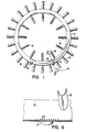
- the augmentor consists of a flameholder assembly generally indicated by reference numeral 10 having a pilot section 12, igniter ports 14 and 16 and a plurality of radial gutters 18 extending radially inwardly and outwardly and circumferentially spaced around the pilot section 12.
- a suitable spray ring 20 injects fuel into the engine exhaust stream indicated by arrow A whereupon the exhaust entrained fuel is directed toward the pilot section 12 as shown by the stream lines indicated by arrow B.
- the pressure pattern will cause the flow to migrate toward the igniter 26 supported in the igniter ports 16 and 14.
- the resulting fuel/air mixture flows over the pilot section 12 and is entrained in the aerodynamic recirculation zone 30.
- the recirculation brings a portion of the fuel/air mixture into close proximity of the igniter 26 and is ignited when the igniter sparks. In some situations the fuel/air mixture reaching the igniter is too lean to be ignited.
- An aperture critically located and oriented in the pilot section 12 serves to improve the ignition and stability characteristics of the augmentor 10.
- a slot 32 is formed in the wall of the pilot section extending transverse to the direction of the air flow in proximity to the leading edge 38 of the pilot section 12 so that the fore edge of slot is substantially in line with the inner surface 40 of the pilot section 12 on the back wall of leading edge 38.
- the slot is machined perpendicular to the engine centerline (parallel with the centerline of pilot section 12) so that it breaks through the inside surface of the pilot section 12 as nearly tangential to the surface 40 as possible.
- Fig. 6 shows a plurality of drilled holes 44 extending laterally relative to the exhaust flow. Likewise each hole is drilled perpendicular to the engine centerline and in proximity to the inside wall 40 of leading edge 38. In either configuration the critical location and orientation is designed to produce a vortical recirculation zone adjacent the igniter.
- a plurality of slots 32 may be located around the circumference of the pilot section 12 to enhance combustion stability.
- the ingestion of fuel/rich gas through these slots 32 or holes 44 so as to provide a plurality of the vortices (zone 42) would improve stability.
- the number of slots and the spacings would depend on the particular application for each augmentor.
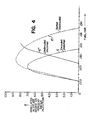
- Fig. 4 the curve represented by the dash line C shows the range of where ignition will ensue over a given fuel air ratio for a given altitude for the shrouded pilot.
- Line C' shows the expanded range for ignition when the invention is employed. While the shrouded pilot gives similar results at the low end of the scale, flameholders without the shroud have not evidenced these results as shown by line C". Hence, the flameholder utilized in the invention produces similar results in the low portion of the lean fuel/air ratio without the encumbering hardware represented by the shroud while greatly extending the rich fuel/air and altitude ignition capability.
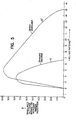
- Figure 5 is actual test data comparing the stability characteristics of the shrouded pilot flameholder and of the flameholder incorporating the invention.
- Line E illustrates the stability regime of the shrouded pilot flameholder and Line E' is that for the flameholder incorporating the invention. Stability will be evidenced under all the fuel/air ratio values for a given altitude while the augmentor is operating under the respective curves.
- the flameholder incorporating the invention has a much extended range of operation both in terms of acceptable fuei/air ratios and in terms of altitude capability.
Landscapes
- Engineering & Computer Science (AREA)
- Chemical & Material Sciences (AREA)
- Combustion & Propulsion (AREA)
- Mechanical Engineering (AREA)
- General Engineering & Computer Science (AREA)
- Nozzles For Spraying Of Liquid Fuel (AREA)
- Testing Of Engines (AREA)
- Combustion Methods Of Internal-Combustion Engines (AREA)
- Control Of Combustion (AREA)
- Pre-Mixing And Non-Premixing Gas Burner (AREA)
Applications Claiming Priority (2)
| Application Number | Priority Date | Filing Date | Title |
|---|---|---|---|
| US80164285A | 1985-11-25 | 1985-11-25 | |
| US801642 | 1985-11-25 |
Publications (3)
| Publication Number | Publication Date |
|---|---|
| EP0224429A2 EP0224429A2 (en) | 1987-06-03 |
| EP0224429A3 EP0224429A3 (en) | 1988-09-14 |
| EP0224429B1 true EP0224429B1 (en) | 1990-11-28 |
Family
ID=25181670
Family Applications (1)
| Application Number | Title | Priority Date | Filing Date |
|---|---|---|---|
| EP86630174A Expired - Lifetime EP0224429B1 (en) | 1985-11-25 | 1986-11-20 | Gas turbine engine augmentor |
Country Status (9)
| Country | Link |
|---|---|
| EP (1) | EP0224429B1 (enExample) |
| JP (1) | JPS62129528A (enExample) |
| KR (1) | KR940008267B1 (enExample) |
| CN (1) | CN1007640B (enExample) |
| AU (1) | AU593858B2 (enExample) |
| CA (1) | CA1281554C (enExample) |
| DE (1) | DE3675896D1 (enExample) |
| IL (1) | IL80634A (enExample) |
| YU (2) | YU201686A (enExample) |
Families Citing this family (12)
| Publication number | Priority date | Publication date | Assignee | Title |
|---|---|---|---|---|
| IL93630A0 (en) * | 1989-03-27 | 1990-12-23 | Gen Electric | Flameholder for gas turbine engine afterburner |
| JP5375433B2 (ja) * | 2009-08-21 | 2013-12-25 | 株式会社Ihi | アフタバーナ及び航空機エンジン |
| US20110219776A1 (en) * | 2010-03-15 | 2011-09-15 | General Electric Company | Aerodynamic flame stabilizer |
| CN102200292B (zh) * | 2010-03-26 | 2015-01-21 | 北京航空航天大学 | 带凹腔的支板火焰稳定装置及火焰稳定方法 |
| JP2013181473A (ja) * | 2012-03-02 | 2013-09-12 | Ihi Corp | アフタバーナ及び航空機エンジン |
| CN103884024B (zh) * | 2014-04-03 | 2016-01-20 | 北京航空航天大学 | 一种能够组织燃烧并将火焰传导到外涵道气流的联焰装置 |
| CN105650642B (zh) * | 2016-02-04 | 2019-04-30 | 中国科学院工程热物理研究所 | 一种可形成低速区的喷嘴、喷嘴阵列和燃烧器 |
| CN105841191B (zh) * | 2016-03-30 | 2018-07-06 | 中国科学院工程热物理研究所 | 一种v型火焰稳定器尾缘结构 |
| CN106678877A (zh) * | 2016-11-15 | 2017-05-17 | 西北工业大学 | 一种加有v型槽环形火焰稳定器的一体化加力燃烧室 |
| CN110486148A (zh) * | 2017-08-29 | 2019-11-22 | 熵零技术逻辑工程院集团股份有限公司 | 一种加力燃烧室高负荷响应发动机 |
| CN109611887B (zh) * | 2018-11-01 | 2020-10-09 | 中国航发沈阳发动机研究所 | 一种燃烧装置 |
| CN114992674B (zh) * | 2022-06-20 | 2024-03-19 | 中国航发贵阳发动机设计研究所 | 一种外置式接力点火及起动供油装置 |
Family Cites Families (5)
| Publication number | Priority date | Publication date | Assignee | Title |
|---|---|---|---|---|
| GB744178A (en) * | 1953-03-26 | 1956-02-01 | Rolls Royce | Improvements relating to combustion equipment of gas-turbine engines |
| FR1199822A (fr) * | 1958-07-11 | 1959-12-16 | Nord Aviat | Perfectionnements aux stabilisateurs de flammes dans les propulseurs à réaction |
| GB886700A (en) * | 1959-11-05 | 1962-01-10 | Rolls Royce | Reheat combustion equipment for jet propulsion engines |
| FR2429326A1 (fr) * | 1978-06-22 | 1980-01-18 | Snecma | Perfectionnements aux dispositifs accroche-flammes pour chambres de combustion, notamment pour canaux de post-combustion de turboreacteurs |
| US4423595A (en) * | 1982-05-27 | 1984-01-03 | United Technologies Corporation | Augmentor residual fuel drain apparatus |
-
1986
- 1986-10-27 CA CA000521471A patent/CA1281554C/en not_active Expired - Lifetime
- 1986-11-14 IL IL80634A patent/IL80634A/xx not_active IP Right Cessation
- 1986-11-20 DE DE8686630174T patent/DE3675896D1/de not_active Expired - Lifetime
- 1986-11-20 EP EP86630174A patent/EP0224429B1/en not_active Expired - Lifetime
- 1986-11-21 AU AU65626/86A patent/AU593858B2/en not_active Ceased
- 1986-11-25 YU YU02016/86A patent/YU201686A/xx unknown
- 1986-11-25 CN CN86108062A patent/CN1007640B/zh not_active Expired
- 1986-11-25 JP JP61280537A patent/JPS62129528A/ja active Granted
- 1986-11-25 KR KR1019860009936A patent/KR940008267B1/ko not_active Expired - Lifetime
- 1986-11-28 YU YU02036/86A patent/YU203686A/xx unknown
Also Published As
| Publication number | Publication date |
|---|---|
| AU593858B2 (en) | 1990-02-22 |
| DE3675896D1 (de) | 1991-01-10 |
| EP0224429A3 (en) | 1988-09-14 |
| JPH0587654B2 (enExample) | 1993-12-17 |
| YU201686A (en) | 1990-06-30 |
| KR870005163A (ko) | 1987-06-05 |
| IL80634A0 (en) | 1987-02-27 |
| YU203686A (en) | 1990-06-30 |
| CN1007640B (zh) | 1990-04-18 |
| KR940008267B1 (ko) | 1994-09-09 |
| JPS62129528A (ja) | 1987-06-11 |
| AU6562686A (en) | 1987-05-28 |
| EP0224429A2 (en) | 1987-06-03 |
| IL80634A (en) | 1991-12-15 |
| CA1281554C (en) | 1991-03-19 |
| CN86108062A (zh) | 1987-07-01 |
Similar Documents
| Publication | Publication Date | Title |
|---|---|---|
| EP0169431B1 (en) | Gas turbine combustor | |
| EP1010946B1 (en) | Combustor for a gas turbine engine | |
| US4271674A (en) | Premix combustor assembly | |
| EP0153842B1 (en) | Combustion equipment | |
| US5396761A (en) | Gas turbine engine ignition flameholder with internal impingement cooling | |
| CA1050286A (en) | Augmentor flameholding apparatus | |
| EP1010945B1 (en) | Fuel injector bar for a gas turbine combustor | |
| US3643430A (en) | Smoke reduction combustion chamber | |
| US8272219B1 (en) | Gas turbine engine combustor having trapped dual vortex cavity | |
| EP0224429B1 (en) | Gas turbine engine augmentor | |
| US4052844A (en) | Gas turbine combustion chambers | |
| US10704787B2 (en) | Closed trapped vortex cavity pilot for a gas turbine engine augmentor | |
| JPS5826498B2 (ja) | ガスタ−ビンエンジン用燃焼装置 | |
| EP1764555A2 (en) | Augmentor radial fuel spray bar with counterswirling heat shield | |
| GB1048968A (en) | Combustion chamber for a gas turbine engine | |
| US4765136A (en) | Gas turbine engine augmentor | |
| US20070028595A1 (en) | High pressure gas turbine engine having reduced emissions | |
| US6141954A (en) | Premixing fuel injector with improved flame disgorgement capacity | |
| US6050096A (en) | Fuel injector arrangement for a combustion apparatus | |
| US7568346B2 (en) | Method and apparatus for assembling a flameholder for an augmenter | |
| USRE30160E (en) | Smoke reduction combustion chamber | |
| US4179881A (en) | Premix combustor assembly | |
| US4539811A (en) | Multi-port dump combustor | |
| US4170111A (en) | Thrust augmentor | |
| US5642621A (en) | Dual head combustion chamber |
Legal Events
| Date | Code | Title | Description |
|---|---|---|---|
| PUAI | Public reference made under article 153(3) epc to a published international application that has entered the european phase |
Free format text: ORIGINAL CODE: 0009012 |
|
| AK | Designated contracting states |
Kind code of ref document: A2 Designated state(s): CH DE FR GB LI |
|
| PUAL | Search report despatched |
Free format text: ORIGINAL CODE: 0009013 |
|
| AK | Designated contracting states |
Kind code of ref document: A3 Designated state(s): CH DE FR GB LI |
|
| 17P | Request for examination filed |
Effective date: 19890308 |
|
| 17Q | First examination report despatched |
Effective date: 19890629 |
|
| GRAA | (expected) grant |
Free format text: ORIGINAL CODE: 0009210 |
|
| AK | Designated contracting states |
Kind code of ref document: B1 Designated state(s): CH DE FR GB LI |
|
| ET | Fr: translation filed | ||
| REF | Corresponds to: |
Ref document number: 3675896 Country of ref document: DE Date of ref document: 19910110 |
|
| PLBE | No opposition filed within time limit |
Free format text: ORIGINAL CODE: 0009261 |
|
| STAA | Information on the status of an ep patent application or granted ep patent |
Free format text: STATUS: NO OPPOSITION FILED WITHIN TIME LIMIT |
|
| PGFP | Annual fee paid to national office [announced via postgrant information from national office to epo] |
Ref country code: CH Payment date: 19911015 Year of fee payment: 6 |
|
| 26N | No opposition filed | ||
| PG25 | Lapsed in a contracting state [announced via postgrant information from national office to epo] |
Ref country code: CH Effective date: 19921130 Ref country code: LI Effective date: 19921130 |
|
| REG | Reference to a national code |
Ref country code: CH Ref legal event code: PL |
|
| REG | Reference to a national code |
Ref country code: GB Ref legal event code: IF02 |
|
| PGFP | Annual fee paid to national office [announced via postgrant information from national office to epo] |
Ref country code: GB Payment date: 20051004 Year of fee payment: 20 |
|
| PGFP | Annual fee paid to national office [announced via postgrant information from national office to epo] |
Ref country code: FR Payment date: 20051104 Year of fee payment: 20 |
|
| PGFP | Annual fee paid to national office [announced via postgrant information from national office to epo] |
Ref country code: DE Payment date: 20051130 Year of fee payment: 20 |
|
| PG25 | Lapsed in a contracting state [announced via postgrant information from national office to epo] |
Ref country code: GB Free format text: LAPSE BECAUSE OF EXPIRATION OF PROTECTION Effective date: 20061119 |
|
| REG | Reference to a national code |
Ref country code: GB Ref legal event code: PE20 |