EP0224326A1 - Verfahren für die Montage elektrischer Speicherbatterien - Google Patents
Verfahren für die Montage elektrischer Speicherbatterien Download PDFInfo
- Publication number
- EP0224326A1 EP0224326A1 EP86308057A EP86308057A EP0224326A1 EP 0224326 A1 EP0224326 A1 EP 0224326A1 EP 86308057 A EP86308057 A EP 86308057A EP 86308057 A EP86308057 A EP 86308057A EP 0224326 A1 EP0224326 A1 EP 0224326A1
- Authority
- EP
- European Patent Office
- Prior art keywords
- notch
- lugs
- partition
- mould
- intercell
- Prior art date
- Legal status (The legal status is an assumption and is not a legal conclusion. Google has not performed a legal analysis and makes no representation as to the accuracy of the status listed.)
- Withdrawn
Links
- 238000000034 method Methods 0.000 title claims abstract description 10
- 238000003860 storage Methods 0.000 title claims abstract description 7
- 238000005192 partition Methods 0.000 claims abstract description 27
- 239000000463 material Substances 0.000 claims abstract description 13
- 239000004033 plastic Substances 0.000 claims abstract description 12
- 229920003023 plastic Polymers 0.000 claims abstract description 12
- 230000008878 coupling Effects 0.000 claims description 2
- 238000010168 coupling process Methods 0.000 claims description 2
- 238000005859 coupling reaction Methods 0.000 claims description 2
- 238000003825 pressing Methods 0.000 claims description 2
- 210000004027 cell Anatomy 0.000 description 18
- 238000007789 sealing Methods 0.000 description 5
- PXHVJJICTQNCMI-UHFFFAOYSA-N Nickel Chemical compound [Ni] PXHVJJICTQNCMI-UHFFFAOYSA-N 0.000 description 3
- 238000004519 manufacturing process Methods 0.000 description 3
- 239000002253 acid Substances 0.000 description 2
- 239000011149 active material Substances 0.000 description 2
- 239000003792 electrolyte Substances 0.000 description 2
- QELJHCBNGDEXLD-UHFFFAOYSA-N nickel zinc Chemical compound [Ni].[Zn] QELJHCBNGDEXLD-UHFFFAOYSA-N 0.000 description 2
- RYGMFSIKBFXOCR-UHFFFAOYSA-N Copper Chemical compound [Cu] RYGMFSIKBFXOCR-UHFFFAOYSA-N 0.000 description 1
- 229910002640 NiOOH Inorganic materials 0.000 description 1
- 230000001154 acute effect Effects 0.000 description 1
- 238000005266 casting Methods 0.000 description 1
- 239000011530 conductive current collector Substances 0.000 description 1
- 238000010276 construction Methods 0.000 description 1
- 229910052802 copper Inorganic materials 0.000 description 1
- 239000010949 copper Substances 0.000 description 1
- 210000001787 dendrite Anatomy 0.000 description 1
- 239000011888 foil Substances 0.000 description 1
- 238000011065 in-situ storage Methods 0.000 description 1
- 238000005304 joining Methods 0.000 description 1
- 239000002184 metal Substances 0.000 description 1
- 229910052751 metal Inorganic materials 0.000 description 1
- 229910052759 nickel Inorganic materials 0.000 description 1
- BFDHFSHZJLFAMC-UHFFFAOYSA-L nickel(ii) hydroxide Chemical compound [OH-].[OH-].[Ni+2] BFDHFSHZJLFAMC-UHFFFAOYSA-L 0.000 description 1
- JBQYATWDVHIOAR-UHFFFAOYSA-N tellanylidenegermanium Chemical compound [Te]=[Ge] JBQYATWDVHIOAR-UHFFFAOYSA-N 0.000 description 1
- 238000003466 welding Methods 0.000 description 1
Images
Classifications
-
- H—ELECTRICITY
- H01—ELECTRIC ELEMENTS
- H01M—PROCESSES OR MEANS, e.g. BATTERIES, FOR THE DIRECT CONVERSION OF CHEMICAL ENERGY INTO ELECTRICAL ENERGY
- H01M50/00—Constructional details or processes of manufacture of the non-active parts of electrochemical cells other than fuel cells, e.g. hybrid cells
- H01M50/50—Current conducting connections for cells or batteries
- H01M50/528—Fixed electrical connections, i.e. not intended for disconnection
- H01M50/529—Intercell connections through partitions, e.g. in a battery casing
-
- Y—GENERAL TAGGING OF NEW TECHNOLOGICAL DEVELOPMENTS; GENERAL TAGGING OF CROSS-SECTIONAL TECHNOLOGIES SPANNING OVER SEVERAL SECTIONS OF THE IPC; TECHNICAL SUBJECTS COVERED BY FORMER USPC CROSS-REFERENCE ART COLLECTIONS [XRACs] AND DIGESTS
- Y02—TECHNOLOGIES OR APPLICATIONS FOR MITIGATION OR ADAPTATION AGAINST CLIMATE CHANGE
- Y02E—REDUCTION OF GREENHOUSE GAS [GHG] EMISSIONS, RELATED TO ENERGY GENERATION, TRANSMISSION OR DISTRIBUTION
- Y02E60/00—Enabling technologies; Technologies with a potential or indirect contribution to GHG emissions mitigation
- Y02E60/10—Energy storage using batteries
-
- Y—GENERAL TAGGING OF NEW TECHNOLOGICAL DEVELOPMENTS; GENERAL TAGGING OF CROSS-SECTIONAL TECHNOLOGIES SPANNING OVER SEVERAL SECTIONS OF THE IPC; TECHNICAL SUBJECTS COVERED BY FORMER USPC CROSS-REFERENCE ART COLLECTIONS [XRACs] AND DIGESTS
- Y10—TECHNICAL SUBJECTS COVERED BY FORMER USPC
- Y10T—TECHNICAL SUBJECTS COVERED BY FORMER US CLASSIFICATION
- Y10T29/00—Metal working
- Y10T29/49—Method of mechanical manufacture
- Y10T29/49002—Electrical device making
- Y10T29/49108—Electric battery cell making
Definitions
- This invention relates to electric storage batteries and more particularly a method for providing a sealed intercell connector therefor.
- Electric storage batteries comprise essentially a partitioned container having a plurality of compartments, each of which contains an electrochemically-active cell element immersed in an electrolyte.
- Each cell element typically comprises a stack of alternating positive and negative polarity plates separated one from the other by a microporous dendrite growth-suppressing sheet known as a separator.
- Each of these plates comprises a conductive current collector having an active material deposited thereon or therein depending on the nature of the battery (e.g., lead-acid (Pb-acid), nickel-zinc (Ni-Zn), etc.).
- the current collector supports its associated active material relative to the other plates in the element and conducts electrical current substantially uniformly throughout the plate.
- the current collectors each have a conductive member, such as a tab, projecting therefrom for coupling that current collector to other current collectors of like polarity within the cell element (e.g., for joining the positive polarity plates together).
- a conductive member such as a tab
- One well-known means for electrically connecting the tabs of like polarity plates is a bar of metal, known as a plate strap, cast on to the tabs.
- Another well-known means for connecting the tabs is a simple bundle of several plate tabs gathered together atop the cell element. Each cell element is electrically joined (e.g., in electrical series) through the intercell partition to a cell element in the next adjacent compartment.
- the plate connecting means i.e., plate strap or tab bundle
- the plate connecting means typically includes an upstanding lug which is electrically joined to a similar lug on the adjacent cell element via an intercell connector passing through an aperture in the intercell partition.
- the intercell connector is sealed within the aperture to prevent leakage of electrolyte between the adjacent compartments.
- the intercell connector is positioned in a notch formed in the top of the intercell partition; a mould is placed over the lugs, notch and partition; and synthetic plastics material is injected into the mould to fill the notch, embed the intercell connector and encapsulate the lugs.
- the present invention comprehends a method of forming an intercell connector seal between adjacent cells of an electric storage battery comprising the steps of: providing a container having at least two adjacent cell compartments separated by an intercell partition having a notch in the top edge thereof; positioning cell elements in each of the compartments, which elements each include an upstanding lug for connection to a similar lug on the next adjacent cell element via the notch in the partition; positioning a compressible, elastic collar about the root of each of the lugs; positioning the elements in their respective compartment such that the collars abut the partition beneath the notch; forming an intercell connector between the adjacent lugs through the notch in the partition; positioning a mould over the lugs, collars, notch and surrounding partition and pressing it into sealing engagement therewith so as to compress the collars against the partition beneath the notch and cause them to conform to the shape of the lug roots and surrounding mould; and finally injecting synthetic plastics material into the mould so as to fill the notch, embed the intercell connector in the synthetic plastics material, encapsulate the
- the elastic collar will preferably comprise a tetra-seal having a rectangular cross-section (though an O-ring is also acceptable) and is positioned about the roots of the lugs before the intercell connector is made.
- the intercell connector may then be made in a variety of ways either before or after the elements are placed in the compartments.
- the intercell connector may be formed by simply welding lugs directly to each other or a separate, intermediate piece joined to each lug and bridging the partition through the notch.
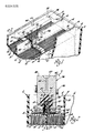
- Figure l shows a battery case 2 having intercell partitions 4 defining individual cell compartments 6 for receiving and retaining cell elements 8 therein.
- the cell elements 8 comprise a plurality of positive plates l0 (e.g., nickel hydroxide (NiOOH)) and alternately-spaced negative plates l2 (e.g.,Zinc (Zn)).
- Each of the positive plates l0 has a tab l4 (e.g., nickel (Ni) Foil) extending therefrom (see Figure 2) while each of the negative plates l2 has tab l6 (e.g., Ni Foil) extending therefrom.
- the separate tabs l4 are bundled together to electrically join the separate positive plates together.
- each tab bundle is then bent upwardly to form a positive intercell connector lug l8 and a negative intercell connector lug 20, respectively.
- a rubber tetra-seal type collar 22, having a rectangular cross-section, is positioned over each lug l8 and 20 at the roots 24 and 26 thereof adjacent bends 23 and 25 where the lugs join the tabs l4 and l6 respectively.
- a U-shaped, copper intercell connector 28 is positioned between the tips of the lugs l8 and 20 and welded thereto as indicated by the weld nuggets 30.
- the cell elements 8 are then positioned in their respective compartments 6 such that the intercell connector 28 falls within a notch 32 formed in the intercell partition 4 and each elastic collar 22 abuts the partition 4 at a point 34 just beneath the notch 32.
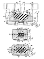
- a mould 36 comprising mould halves 38 and 40 and defining mould cavity 42 are brought together about the lugs l8 and 20, collars 22 and notch 32 as best shown in Figure 2.
- the lower ends of the mould halves 38 and 40 have plates 44 and 46 respectively bolted thereto.
- the plates 44 and 46 have cutout portions 48 and 50 (see Figure 4) each sized to engage the respective collars 22 so as to compress them against the intercell partition 4 at point 34 and constrictively about the lugs l8 and 20 to form a tight seal therewith.
- the cutouts 48 and 50 are bevelled as at 52 and 54 respectively for guiding the mould into place and causing the collars 22 to conform tightly to the roots 24 and 26 of the lugs l8 and 20.
- clamping means 56 pulls the mould halves 38 and 40 together into sealing engagement with the faces 3l of the partition 4 surrounding the notch 32, so as to compress the collars 22 against the partition portion 34 and about the lugs l8 and 20.
- the cavity 42 formed between the mould halves 38 and 40 extends slightly beyond the edges 57 and 58 of the aperture 32 so as to provide overlapping portions 60 of injected synthetic plastics material 62.
- an appropriate synthetic plastics material is introduced into the mould cavity 42 via the opening 64 and runner 66.
- the synthetic plastics material will preferably be hot injection-moulded and comprise the same material as the container 2.
- intercell connector lugs need not be tab bundles, but rather may be of one-piece construction such as is formed by casting in situ at the time a plate strap is cast to the electrode tabs. Accordingly, while the invention has been described primarily in terms of a specific embodiment thereof it is not intended to be limited thereto but rather only to the extent set forth hereafter in the claims which follow.
Landscapes
- Chemical & Material Sciences (AREA)
- Chemical Kinetics & Catalysis (AREA)
- Electrochemistry (AREA)
- General Chemical & Material Sciences (AREA)
- Connection Of Batteries Or Terminals (AREA)
Applications Claiming Priority (2)
| Application Number | Priority Date | Filing Date | Title |
|---|---|---|---|
| US801244 | 1985-11-25 | ||
| US06/801,244 US4675991A (en) | 1985-11-25 | 1985-11-25 | Method of assembling electric storage batteries |
Publications (1)
| Publication Number | Publication Date |
|---|---|
| EP0224326A1 true EP0224326A1 (de) | 1987-06-03 |
Family
ID=25180579
Family Applications (1)
| Application Number | Title | Priority Date | Filing Date |
|---|---|---|---|
| EP86308057A Withdrawn EP0224326A1 (de) | 1985-11-25 | 1986-10-17 | Verfahren für die Montage elektrischer Speicherbatterien |
Country Status (3)
| Country | Link |
|---|---|
| US (1) | US4675991A (de) |
| EP (1) | EP0224326A1 (de) |
| CA (1) | CA1273995A (de) |
Families Citing this family (7)
| Publication number | Priority date | Publication date | Assignee | Title |
|---|---|---|---|---|
| US5202198A (en) * | 1992-03-26 | 1993-04-13 | General Motors Corporation | Battery construction and method of connecting terminals to electrodes |
| USRE36102E (en) * | 1991-09-17 | 1999-02-16 | Globe-Union Inc. | Dual lug battery plate construction |
| US5318864A (en) * | 1993-07-12 | 1994-06-07 | Enersafe Corporation | Explosion-resistant storage battery and method of manufacture |
| US5620809A (en) * | 1995-05-08 | 1997-04-15 | Enersafe Corporation | Storage battery and method of manufacture |
| US5686202A (en) * | 1995-10-18 | 1997-11-11 | Hawker Energy Products, Inc. | Stress resistant battery configuration |
| US5834743A (en) * | 1996-11-19 | 1998-11-10 | Gnb Technologies, Inc. | Induction heating apparatus and method for fusing intercell connectors to battery cell terminals |
| US20060216595A1 (en) * | 2005-03-22 | 2006-09-28 | Holliday Rex W | Battery assembly having improved lug profile |
Citations (3)
| Publication number | Priority date | Publication date | Assignee | Title |
|---|---|---|---|---|
| DE2504667A1 (de) * | 1974-02-12 | 1975-08-14 | Incoteca Ind Consult & Technic | Verfahren fuer die montage eines elektrischen akkumulators aus thermoplastmaterial und nach diesem verfahren hergestellte akkumulatorenbatterie |
| GB1533387A (en) * | 1974-12-24 | 1978-11-22 | Chloride Group Ltd | Sealing intercell connections of multi-cell electric batteries |
| GB2014780A (en) * | 1978-02-17 | 1979-08-30 | Hadi Offermann Maschbau | Cell connector for accumulators |
Family Cites Families (1)
| Publication number | Priority date | Publication date | Assignee | Title |
|---|---|---|---|---|
| DE2741934A1 (de) * | 1977-09-17 | 1979-03-29 | Varta Batterie | Zellenverbinder fuer bleiakkumulatoren |
-
1985
- 1985-11-25 US US06/801,244 patent/US4675991A/en not_active Expired - Fee Related
-
1986
- 1986-08-14 CA CA000515944A patent/CA1273995A/en not_active Expired - Lifetime
- 1986-10-17 EP EP86308057A patent/EP0224326A1/de not_active Withdrawn
Patent Citations (3)
| Publication number | Priority date | Publication date | Assignee | Title |
|---|---|---|---|---|
| DE2504667A1 (de) * | 1974-02-12 | 1975-08-14 | Incoteca Ind Consult & Technic | Verfahren fuer die montage eines elektrischen akkumulators aus thermoplastmaterial und nach diesem verfahren hergestellte akkumulatorenbatterie |
| GB1533387A (en) * | 1974-12-24 | 1978-11-22 | Chloride Group Ltd | Sealing intercell connections of multi-cell electric batteries |
| GB2014780A (en) * | 1978-02-17 | 1979-08-30 | Hadi Offermann Maschbau | Cell connector for accumulators |
Also Published As
| Publication number | Publication date |
|---|---|
| CA1273995A (en) | 1990-09-11 |
| US4675991A (en) | 1987-06-30 |
Similar Documents
| Publication | Publication Date | Title |
|---|---|---|
| EP0244943B1 (de) | Elektrische Speicherbatterie | |
| US4800142A (en) | Electric storage battery | |
| JP4979634B2 (ja) | 二次電池のケース素材 | |
| US5256502A (en) | Modular, multicell lead-acid batteries | |
| US6833010B2 (en) | Prismatic battery module and method for manufacturing the same | |
| AU722126B2 (en) | Sealed lead-acid cells and batteries | |
| CN106848137A (zh) | 双极电池总成 | |
| CN101523640A (zh) | 电池和制造电池的方法 | |
| CA1177115A (en) | Battery intercell connector manifold | |
| US4675991A (en) | Method of assembling electric storage batteries | |
| US4171564A (en) | Method of manufacturing electric batteries with heat embedded intercell connectors | |
| EP0478038B1 (de) | Bipolare Batterie und Zusammenbau-Methode | |
| US3692587A (en) | Multicell storage battery | |
| US3746579A (en) | Battery having container in two portions and a method for making it | |
| US3753783A (en) | Battery, components, and method of making | |
| US4764182A (en) | Electric storage battery | |
| US4423123A (en) | Electric storage battery and a method of making the same | |
| US4093785A (en) | Lighter lead storage battery | |
| US5637419A (en) | Up and through battery intercell weld | |
| CA1302492C (en) | Method of making a battery | |
| KR20080038663A (ko) | 이차전지 | |
| US5731103A (en) | Method and apparatus for positioning a battery terminal strap | |
| US2090268A (en) | Method of making inter-cell connections for storage batteries | |
| CN223066355U (zh) | 电池组及电池系统 | |
| EP0217550A1 (de) | Galvanische Zelle |
Legal Events
| Date | Code | Title | Description |
|---|---|---|---|
| PUAI | Public reference made under article 153(3) epc to a published international application that has entered the european phase |
Free format text: ORIGINAL CODE: 0009012 |
|
| STAA | Information on the status of an ep patent application or granted ep patent |
Free format text: STATUS: THE APPLICATION HAS BEEN WITHDRAWN |
|
| 17P | Request for examination filed |
Effective date: 19861027 |
|
| AK | Designated contracting states |
Kind code of ref document: A1 Designated state(s): DE FR GB |
|
| 18W | Application withdrawn |
Withdrawal date: 19870512 |
|
| RIN1 | Information on inventor provided before grant (corrected) |
Inventor name: BYERS, ROBERT G. |