EP0224084A1 - Adjustable charging device - Google Patents
Adjustable charging device Download PDFInfo
- Publication number
- EP0224084A1 EP0224084A1 EP86115327A EP86115327A EP0224084A1 EP 0224084 A1 EP0224084 A1 EP 0224084A1 EP 86115327 A EP86115327 A EP 86115327A EP 86115327 A EP86115327 A EP 86115327A EP 0224084 A1 EP0224084 A1 EP 0224084A1
- Authority
- EP
- European Patent Office
- Prior art keywords
- loading device
- components
- guide element
- extraction member
- shell segments
- Prior art date
- Legal status (The legal status is an assumption and is not a legal conclusion. Google has not performed a legal analysis and makes no representation as to the accuracy of the status listed.)
- Granted
Links
Images

Classifications
-
- E—FIXED CONSTRUCTIONS
- E21—EARTH DRILLING; MINING
- E21D—SHAFTS; TUNNELS; GALLERIES; LARGE UNDERGROUND CHAMBERS
- E21D9/00—Tunnels or galleries, with or without linings; Methods or apparatus for making thereof; Layout of tunnels or galleries
- E21D9/12—Devices for removing or hauling away excavated material or spoil; Working or loading platforms
Definitions
- the invention relates to a loading device for a extraction member, in particular a loading member designed as a screw conveyor, which optionally also forms the extraction member, the loading device cooperating with at least one guide element arranged outside the working area of the extraction member for the material to be removed.
- the loading tools are designed as loading screws which can be swiveled arm-like on both sides of the conveying device with a supporting frame.
- the loading augers and chutes forming loader parallel to them are arranged in the rear arms in the rear region.
- the loading screws are at least partially equipped with crushing tools on their screw web, the chutes serving as crushing abutments in this area.
- the loading device thus simultaneously acts as an extraction organ.
- the support frames can be swiveled independently of one another about their vertical axes in order to ensure that the entire machine can move around curves.
- Tunneling machines of the type mentioned are well suited for underground mining, where there are only low removal heights. In many cases, the actual extraction elements are connected upstream of the loading devices, so that the loading devices themselves only have to pick up the cut material falling to the ground and possibly have to shred them.
- the invention is based on the generic part of the main patent claim, the task of eliminating the disadvantages of the prior art and creating a continuous flow of funding.
- the guide element or components interacting therewith can or are trackable to the lifting or pivoting movements of the extraction member or the loading device. This measure ensures that a continuous removal of the material obtained is ensured at any height position of the loading device or of the extraction member.
- the detour via the "Erditz" interim storage facility is thus avoided, the overall efficiency being able to be increased in a not inconsiderable manner.
- the tracking is preferably inevitable, i.e. simultaneous to the lifting or swiveling movement.
- a variant of the invention shows that the components are approximately plate-shaped.
- the plates are arranged to be longitudinally movable below the guide element and are preferably mounted to be longitudinally movable at least in their outer end regions by rollers or sliding guides.
- the guide element is advanced.
- This device can also be used in underground construction, since it can only be used to detect lower removal heights.
- the components interacting with the guide element as shell segments with a defined radius of curvature, which overlap one another in the circumferential direction and are at least partially movable in the circumferential direction.
- an opening is provided above the guide element, through which the material is fed to a belt or plate conveyor for further removal.
- the guide element has a rounded cross section and serves as a receiving element for the shell segments in the bottom receiving region of the extraction member.
- Such a device is universally suitable both for direct propulsion in the longitudinal direction and for cutting off by means of lifting and swiveling movements of the extraction member.
- At least the shell segment facing the work area of the extraction element or the loading device is rotatably supported at a defined radial distance about the horizontal axis of the extraction element or the loading device, connecting struts extending between the inner peripheral surface of the shell segments and the associated bearings.
- the suspension or mounting of the components interacting with the guide element is preferably carried out in the area of the supporting structure of a chassis or the like.
- the shell segments in their end regions (seen in the circumferential direction) with radial shoulders which form stop surfaces for the retraction or extension of the shell segments.
- the radial lugs engage in a claw-like manner and are at least partially arranged in corresponding guide grooves.
- a telescopic extension or retraction in the circumferential direction can thus be ensured with a small space requirement. This arrangement ensures that irrespective of the removal height, the material obtained can always be removed in the same direction in the direction of the opening, without significant material loss occurring in between.
- the radial gap between the cup-shaped guide elements and the extraction member may be constant.
- the material is usually broken during the loading process. It could be advantageous here to guide the shell segment initially located in the working area in such a way that an approximately funnel-shaped receiving area is formed.
- the longitudinal or rotary movement of the channel-shaped guide elements is preferably carried out by means of push elements, such as Hydraulic cylinders, spindles, racks or the like.
- the adjustment movement of the guide elements can be realized by contact switches or by optical switching devices. As a result, the stroke is set as a function of the dumping depth or the adaptation to the irregularly running work surface is achieved.
- the control of the guide elements must be adapted to the application in each case.
- the control can both inevitably, i.e. take place simultaneously with the height adjustment or also lead the height adjustment in order to ensure in any case that the material loss in the loading area is as small as possible.
- FIG. 1 shows a mining element 1, which consists of a screw conveyor, not shown, which is provided with crushing elements in the outer peripheral region.
- a loading process takes place at the same time along the slope direction of the auger.
- at least one channel-shaped guide element is provided outside the working area of the extraction member 1.
- this device which corresponds approximately to DE-PS 33 23 395, is only able to take up material cut off from a separate extraction organ in the bottom region 3 and, if necessary, to shred it.
- the screw were designed as a lifting and lowering extraction device 1 at the same time, the material obtained would simply fall to the ground and would then have to be collected in subsequent steps. However, this reduces the overall efficiency.
- the area of the channel-shaped guide element 2 be modified so that it is able to follow the movements of the extraction element 1.
- FIG. 1 shows the initial state.
- the extraction member 1 is located on the bottom 3 and the plate 4 or the plates are flush with the guide element 2 finally 7.
- the longitudinal movement of the plates 4 takes place by means of hydraulic cylinders 8.
- the fastenings 9, 10 of the longitudinal guides 5, 6 are carried out both in the lower region 11 of the guide element 2 and on the support structure 12 of a vehicle (not shown further).
- the number 13 represents a through-opening through which the extracted and loaded material is fed onto a discharge conveyor 14.
- Figure 2 shows an alternative embodiment of the inventive concept. The same components are provided with the same reference symbols.
- the extraction member 1 and the guide element 2 are shown again, which serves here, among other things, as a receiving part of further shell segments 15, 16.
- a through opening 13 is provided, which serves for the removal of the material obtained onto a take-off conveyor 14.
- the guide element 2 is rigid, while the shell segments 15, 16 can be pivoted about the horizontal axis 17 of the extraction member 1.
- Struts 20, 21 are arranged between bearings 18 and the inner circumferential surface 19 of the shell segments 15, 16, by means of which the rotary movement can be generated.
- the attachment 22 of the bearing 18 is made directly on the support structure 23 of a chassis, not shown.
- the rotary movement takes place via hydraulic cylinders 24 which engage the strut 21.
- the curvature of the shell segments 15, 16 and of the guide element 2 corresponds approximately to the curvature of the extraction member 1.
- the hydraulic cylinder 24 By actuating the hydraulic cylinder 24, the shell segments 15, 16 are retracted or extended.
- the end regions of the shell segments 15, 16 are provided with cams 25, 26, 27, 28, at least the cams 26 engaging in corresponding guide grooves 29.
- Figures 3 and 4 show the devices of Figures 1 and 2 in the operating state.
- Figure 3 corresponds to Figure 1 with the difference that the plates 4 are extended in the drive direction as soon as the extraction member 1 lifts off the ground and makes a cut in the horizontal or vertical direction.
- Figure 4, which corresponds to Figure 2 can also be seen. It can also be seen here that the shell segments 15, 16 can be advanced in the circumferential direction depending on the working height of the extraction member 1.
- the adjustment device is actuated by contact switches or the like.
- the stroke H is set as a function of the depth of cut T or the adaptation to the irregularly running work surface is achieved.
Abstract
Description
Die Erfindung betrifft eine Ladevorrichtung für ein Gewinnungsorgan, insbesondere als Förderschnecke ausgebildetes Ladeorgan, die ggf. gleichzeitig das Gewinnungsorgan bildet, wobei die Ladevorrichtung mit mindestens einem ausßerhalb des Arbeitsbereiches des Gewinnungsorganes angeordneten Führungselement für das abzufördernde Material zusammenwirkt.The invention relates to a loading device for a extraction member, in particular a loading member designed as a screw conveyor, which optionally also forms the extraction member, the loading device cooperating with at least one guide element arranged outside the working area of the extraction member for the material to be removed.
Durch die DE-PS 3323395 ist eine Vortriebsmaschine für Bergbaustrecken und Tunnelstrecken vorbekannt. Die Ladewerkzeuge sind als Ladeschnecken ausgebildet, die mit Tragrahmen beiderseits der Fördervorrichtung armartig schwenkbar sind. In den Tragarmen sind im rückwärtigen Bereich der Ladeschnecken und zu diesen parallel laderinnenbildende Schurren angeordnet. Die Ladeschnecken sind auf ihrem Schneckensteg zumindest bereichsweise mit Brechwerkzeugen besetzt, wobei die Schurren in diesem Bereich als Brechwiderlager dienen. Somit wirkt die Ladevorrichtung gleichzeitig als Gewinnungsorgan. Die Tragrahmen sind unabhängig voneinander um ihre vertikalen Achsen schwenkbar sein, um so eine gewisse Kurvengängigkeit der gesamten Maschine zu gewährleisten. Vortriebsmaschinen der angesprochenen Gattung eignen sich gut im Untertagebau, wo lediglich geringe Abtragshöhen gegeben sind. Vielfach sind den Ladevorrichtungen die eigentlichen Gewinnungsorgane vorgeschaltet, so daß die Ladevorrichtungen selber nur das zu Boden fallende abgehauene Material aufnehmen und ggf. noch zerkleinern müssen.DE-PS 3323395 a tunneling machine for mining and tunnel routes is already known. The loading tools are designed as loading screws which can be swiveled arm-like on both sides of the conveying device with a supporting frame. The loading augers and chutes forming loader parallel to them are arranged in the rear arms in the rear region. The loading screws are at least partially equipped with crushing tools on their screw web, the chutes serving as crushing abutments in this area. The loading device thus simultaneously acts as an extraction organ. The support frames can be swiveled independently of one another about their vertical axes in order to ensure that the entire machine can move around curves. Tunneling machines of the type mentioned are well suited for underground mining, where there are only low removal heights. In many cases, the actual extraction elements are connected upstream of the loading devices, so that the loading devices themselves only have to pick up the cut material falling to the ground and possibly have to shred them.
Beim Einsatz derartiger Gewinnungsorgane im Tagebau sind jedoch Arbeitsflächen mit Abtragshöhen in der Größe des zwei- bis dreifachen Schneckendurchmessers nichts ungewöhnliches. Das dabei im Hochschnitt arbeitende Gewinnungsorgan löst das Material aus der Wand, läßt es auf den Erdboden fallen, wobei das Material - wie bereits oben angesprochen - von Ladevorrichtungen aufgenommen wird.When using such extraction elements in open-cast mining, however, work surfaces with removal heights in the size of two to three times the screw diameter are not uncommon. The extraction organ, which works in a high cut, releases the material from the wall and lets it fall to the ground, the material being - as already mentioned above - taken up by loading devices.
Bei diesem Verfahren ist eine zeitlich begrenzte Zwischenlagerung vor dem Ladeschild unumgänglich. Dadurch wird der Gesamtwirkungsgrad verschlechtert und zusätzliche Verluste infolge seitlich abfließenden Materiales unvermeidbar.With this method, temporary storage in front of the loading plate is essential. As a result, the overall efficiency deteriorates and additional losses due to laterally flowing material are unavoidable.
Der Erfindung liegt, ausgehend vom gattungsbildenden Teil des Hauptpatentanspruches, die Aufgabe zugrunde, die Nachteile des Standes der Technik zu beseitigen und einen kontinuierlichen Förderfluß zu schaffen.The invention is based on the generic part of the main patent claim, the task of eliminating the disadvantages of the prior art and creating a continuous flow of funding.
Diese Aufgabe wird erfindungsgemäß dadurch gelöst, daß das Führungselement bzw. damit zusammenwirkende Bauteile den Hub- oder Schwenkbewegungen des Gewinnungsorganes bzw. der Ladevorrichtung nachführbar ist bzw. sind. Durch diese Maßnahme wird erreicht, daß in jeder Höhenstellung der Ladevorrichtung bzw. des Gewinnungsorganes eine kontinuierliche Abförderung des gewonnenen Materials sichergestellt ist. Der Umweg über das Zwischenlager "Erdboden" wird somit umgangen, wobei der Gesamtwirkungsgrad in nicht unerheblicher Weise gesteigert werden kann. Die Nachführung erfolgt hierbei vorzugsweise zwangsläufig, d.h. simultan zur Hub- bzw. Schwenkbewegung.This object is achieved in that the guide element or components interacting therewith can or are trackable to the lifting or pivoting movements of the extraction member or the loading device. This measure ensures that a continuous removal of the material obtained is ensured at any height position of the loading device or of the extraction member. The detour via the "Erdboden" interim storage facility is thus avoided, the overall efficiency being able to be increased in a not inconsiderable manner. The tracking is preferably inevitable, i.e. simultaneous to the lifting or swiveling movement.
Eine Variante der Erfindung zeigt auf, daß die Bauteile etwa plattenförmig ausgebildet sind. Die Platten sind unterhalb des Führungselementes längsbeweglich angeordnet und sind vorzugsweise zumindest in ihren äußeren Endbereichen durch Rollen oder Gleitführungen längsbeweglich gelagert. In Abhängigkeit von dem sich kontinuierlich auf- und abbewegenden Gewinnungsorgan erfolgt eine Zustellbewegung des Führungselementes. Diese Vorrichtung ist auch im Untertagebau einsetzbar, da hiermit nur geringere Abtragshöhen erfaßt werden können.A variant of the invention shows that the components are approximately plate-shaped. The plates are arranged to be longitudinally movable below the guide element and are preferably mounted to be longitudinally movable at least in their outer end regions by rollers or sliding guides. Depending on the extraction organ moving up and down continuously, the guide element is advanced. This device can also be used in underground construction, since it can only be used to detect lower removal heights.
Alternativ dazu wird vorgeschlagen, die mit dem Führungselement zusammenwirkenden Bauteile als Schalensegmente mit definiertem Krümmungsradius auszubilden, die einander in Umfangsrichtung überlappen und zumindest teilweise in Umfangsrichtung beweglich ausgebildet sind.As an alternative to this, it is proposed to design the components interacting with the guide element as shell segments with a defined radius of curvature, which overlap one another in the circumferential direction and are at least partially movable in the circumferential direction.
Oberhalb des Führungselementes ist analog zum Stand der Technik eine Öffnung vorgesehen, durch die das Material einen Band- oder Plattenförderer zum weiteren Abtransport zugeführt wird.Analogously to the prior art, an opening is provided above the guide element, through which the material is fed to a belt or plate conveyor for further removal.
Einem weiteren Gedanken der Erfindung gemäß weist das Führungselement einen gerundeten Querschnitt auf und dient im bodenseitigen Aufnahmebereich des Gewinnungsorganes als Aufnahmeelement für die Schalensegmente. Eine solche Vorrichtung ist universell sowohl für den direkten Vortrieb in Längsrichtung geeignet als auch für das Abhauen mittels Hub- und Schwenkbewegungen des Gewinnungsorganes einsetzbar.According to a further idea of the invention, the guide element has a rounded cross section and serves as a receiving element for the shell segments in the bottom receiving region of the extraction member. Such a device is universally suitable both for direct propulsion in the longitudinal direction and for cutting off by means of lifting and swiveling movements of the extraction member.
Zumindest das dem Arbeitsbereich des Gewinnungsorganes bzw. der Ladevorrichtung zugewandte Schalensegment ist mit definiertem radialem Abstand um die Horizontalachse des Gewinnungsorganes bzw. der Ladevorrichtung drehbar gelagert, wobei sich zwischen der inneren Umfangsfläche der Schalensegmente und den zugehörigen Lagern Verbindungstreben erstrecken. Die Aufhängung bzw. Lagerung der mit dem Führungselement zusammenwirkenden Bauteile erfolgt vorzugsweise im Bereich der Tragkonstruktion eines Fahrwerkes oder dgl.At least the shell segment facing the work area of the extraction element or the loading device is rotatably supported at a defined radial distance about the horizontal axis of the extraction element or the loading device, connecting struts extending between the inner peripheral surface of the shell segments and the associated bearings. The suspension or mounting of the components interacting with the guide element is preferably carried out in the area of the supporting structure of a chassis or the like.
Es wird weiterhin vorgeschlagen, die Schalensegmente in ihren Endbereichen (in Umfangsrichtung gesehen) mit radialen Ansätzen zu versehen, die Anschlagflächen für das Ein- bzw. das Ausfahren der Schalensegmente bilden. Die Radialansätze greifen klauenartig ineinander und sind zumindest teilweise in entsprechenden Führungsnuten angeordnet. Somit kann ein in Umfangsrichtung teleskopartiges Aus- bzw. Einfahren bei geringem Platzbedarf gewährleistet sein. Durch diese Anrodnung wird sichergestellt, daß unabhängig von der Abtragshöhe das gewonnene Material immer gleich in Richtung der Öffnung abgefördert werden kann, ohne daß zwischendurch ein wesentlicher Materialverlust eintritt.It is further proposed to provide the shell segments in their end regions (seen in the circumferential direction) with radial shoulders which form stop surfaces for the retraction or extension of the shell segments. The radial lugs engage in a claw-like manner and are at least partially arranged in corresponding guide grooves. A telescopic extension or retraction in the circumferential direction can thus be ensured with a small space requirement. This arrangement ensures that irrespective of the removal height, the material obtained can always be removed in the same direction in the direction of the opening, without significant material loss occurring in between.
Je nach zu gewinnendem Material kann es sinnvoll sein, daß der radiale Spalt zwischen den schalenförmigen Führungselementen und dem Gewinnungsorgan gleichbleibend ausgebildet ist. Üblicherweise wird das Material während des Ladevorganges noch gebrochen. Hier könnte es von Vorteil sein, das dem Arbeitsbereich zunächst gelegene Schalensegment so zu führen, daß ein etwa trichterförmig sich verjüngender Aufnahmebereich gebildet wird. Die Längs- bzw. die Drehbewegung der rinnenförmigen Führungselemente erfolgt vorzugsweise mittels Schubelementen, wie z.B. Hydraulikzylindern, Spindeln, Zahnstangen oder dgl. In beiden bevorzugten Anwendungsfällen kann die Verstellbewegung der Führungselemente durch Kontaktschalter oder durch optische Schalteinrichtungen realisiert werden. Dadurch wird in Abhängigkeit von der Schüttiefe der Hub eingestellt bzw. die Anpassung an die unregelmässig verlaufende Arbeitsfläche erreicht.Depending on the material to be extracted, it may be useful for the radial gap between the cup-shaped guide elements and the extraction member to be constant. The material is usually broken during the loading process. It could be advantageous here to guide the shell segment initially located in the working area in such a way that an approximately funnel-shaped receiving area is formed. The longitudinal or rotary movement of the channel-shaped guide elements is preferably carried out by means of push elements, such as Hydraulic cylinders, spindles, racks or the like. In both preferred applications, the adjustment movement of the guide elements can be realized by contact switches or by optical switching devices. As a result, the stroke is set as a function of the dumping depth or the adaptation to the irregularly running work surface is achieved.
Die Steuerung der Führungselemente ist in jedem Fall dem Anwendungsfall anzupassen. Die Steuerung kann sowohl zwangsläufig, d.h. simultan zur Höhenverstellung erfolgen oder aber auch der Höhenverstellung voreilen, um so in jedem Fall sicherzustellen, daß der Materialverlust im Ladebereich so gering wie möglich ausfällt.The control of the guide elements must be adapted to the application in each case. The control can both inevitably, i.e. take place simultaneously with the height adjustment or also lead the height adjustment in order to ensure in any case that the material loss in the loading area is as small as possible.
Die Erfindung ist in der Zeichnung dargestellt und wird im folgenden näher beschrieben. Es zeigen
- Fig. 1 Gewinnungsorgan mit längsbeweglichem Führungselement in der Grundstellung
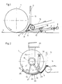
- Fig. 2 Gewinnungsorgan mit schalensegmentförmigen Führungselementen
- Fig. 3 Gewinnungsorgan in angehobener Stellung mit ausfahrendem längsbeweglichem Führungselement
- Fig. 4 Gewinnungsorgan in angehobener Stellung mit in Umfangsrichtung ausfahrenden Schalensegmenten.
- Fig. 1 extraction organ with longitudinally movable guide element in the basic position
- Fig. 2 extraction organ with shell segment-shaped guide elements
- Fig. 3 extraction organ in the raised position with extending longitudinally movable guide element
- Fig. 4 extraction organ in the raised position with shell segments extending in the circumferential direction.
Figur 1 zeigt ein Gewinnungsorgan 1, das aus einer nicht weiter dargestellten Förderschnecke besteht, welche im äußeren Umfangsbereich mit Brechelementen versehen ist. Bedingt durch die schneckenförmige Ausbildung des unterschlächtig arbeitenden Gewinnungsorganes 1 findet gleichzeitig entlang der Steigungsrichtung der Schnecke ein Ladevorgang (Transport) statt. Um ein Widerlager für den Ladevorgang zu bilden, ist mindestens ein rinnenförmig ausgebildetes Führungselement außerhalb des Arbeitsbereiches des Gewinnungsorganes 1 vorgesehen. Diese etwa der DE-PS 33 23 395 entsprechende Einrichtung ist jedoch nur dazu in der Lage, von einem separaten Gewinnungsorgan abgehauenes Material im Bodenbereich 3 aufzunehmen und ggf. noch zu zerkleinern. Würde die Schnecke gleichzeitig als heb- und senkbares Gewinnungsorgan 1 ausgebildet werden, so würde das gewonnene Material lediglich zu Boden fallen und müßte dann in Folgeschritten eingesammelt werden. Dies mindert jedoch den Gesamtwirkungsgrad. Um nun ein kontinuierliches Abfördern gewonnenen Materials - unabhängig von der Arbeitshöhe des Gewinnungsorganes 1 - sicherzustellen, wird vorgeschlagen, daß der Bereich des rinnenförmigen Führungselementes 2 so modifiziert wird, daß er in der Lage ist, den Bewegungen des Gewinnungsorganes 1 zu folgen.FIG. 1 shows a
Dies geschieht gemäß Figur 1 in der Weise, daß unterhalb des Führungselementes 2 mindestens eine in Vortriebsrichtung längsbewegliche Platte 4 vorgesehen ist. Die Platte 4 bzw. die Platten sind z.B. durch Rollen 5,6 längsgeführt. Figur 1 zeigt den Ausgangszustand. Das Gewinnungsorgan 1 befindet sich auf dem Boden 3 und die Platte 4 bzw. die Platten sind bündig mit dem Führungselement 2 abschließend 7 eingefahren. Die Längsbewegung der Platten 4 erfolgt durch Hydraulikzylinder 8. Die Befestigungen 9,10 der Längsführungen 5,6 erfolgt sowohl im unteren Bereich 11 des Führungselementes 2 als auch an der Tragkonstruktion 12 eines nicht weiter dargestellten Fahrzeuges.This is done according to FIG. 1 in such a way that at least one plate 4 which is longitudinally movable in the direction of advance is provided below the
Die Ziffer 13 stellt eine Durchgangsöffnung dar, durch welche das gewonnene und geladene Material auf einen Abzugsförderer 14 aufgegeben wird. Figur 2 zeigt eine alternative Ausführungsform des Erfindungsgedankens. Gleiche Bauteile werden mit gleichen Bezugszeichen versehen. Dargestellt sind wieder das Gewinnungsorgan 1 sowie das Führungselement 2, welches hier unter anderem als Aufnahmeteil weiterer Schalensegmente 15,16 dient. Auch hier ist eine Durchgangsöffnung 13 vorgesehen, die zum Abtransport des gewonnenen Materials auf einen Abzugsförderer 14 dient. Das Führungselement 2 ist starr ausgebildet, während die Schalensegmente 15,16 um die Horizontalachse 17 des Gewinnungsorganes 1 schwenkbar sind. Zwischen Lagern 18 und der inneren Umfangsfläche 19 der Schalensegmente 15,16 sind Streben 20,21 angeordnet, mittels derer die Drehbewegung erzeugbar ist. Die Befestigung 22 der Lager 18 wird direkt an der Tragkonstruktion 23 eines nicht weiter dargestellten Fahrwerkes vorgenommen. Die Drehbewegung erfolgt über Hydraulikzylinder 24, die an der Strebe 21 angreifen. Die Rundung der Schalensegmente 15,16 sowie des Führungselementes 2 entspricht etwa der Krümmung des Gewinnungsorganes 1. Durch Betätigen des Hydraulikzlinders 24 werden diie Schalensegmente 15,16 ein- bzw. ausgefahren. Die Endbereiche der Schalensegmente 15,16 sind mit Nocken 25,26,27,28 versehen, wobei zumindest die Nocken 26 in entsprechende Führungsnuten 29 eingreifen.The
Die Figuren 3 und 4 zeigen die Einrichtungen der Figuren 1 und 2 im Betriebszustand. Figur 3 entspricht herbei Figur 1 mit dem Unterschied, daß die Platten 4 in Vortriebrichtung ausgefahren werden, sobald das Gewinnungsorgan 1 vom Boden abhebt und einen Schnitt in horizontaler oder vertikaler Richtung durchführt. Anaog dazu ist Figur 4 zu sehen, die der Figur 2 entspricht. Auch hier ist erkennbar, daß die Schalensegmente 15,16 in Abhängigkeit von der Arbeitshöhe des Gewinnungsorganes 1 in Umfangsrichtung zustellbar sind.Figures 3 and 4 show the devices of Figures 1 and 2 in the operating state. Figure 3 corresponds to Figure 1 with the difference that the plates 4 are extended in the drive direction as soon as the
In beiden Fällen wird die Verstelleinrichtung durch Kontaktschalter oder dgl. betätigt. Dadurch wird in Abhängigkeit von der Schnittiefe T der Hub H eingestellt bzw. die Anpassung an die unregelmäßig verlaufende Arbeitsfläche erreicht.In both cases, the adjustment device is actuated by contact switches or the like. As a result, the stroke H is set as a function of the depth of cut T or the adaptation to the irregularly running work surface is achieved.
Claims (14)
Priority Applications (1)
| Application Number | Priority Date | Filing Date | Title |
|---|---|---|---|
| AT86115327T ATE72479T1 (en) | 1985-11-28 | 1986-11-05 | ADJUSTABLE LOADER. |
Applications Claiming Priority (2)
| Application Number | Priority Date | Filing Date | Title |
|---|---|---|---|
| DE3542084 | 1985-11-28 | ||
| DE19853542084 DE3542084A1 (en) | 1985-11-28 | 1985-11-28 | LOADING DEVICE ASSOCIATED WITH THE EXTRACTION ORGANIS OF A PITCHING OR EXTRACTION MACHINE |
Publications (2)
| Publication Number | Publication Date |
|---|---|
| EP0224084A1 true EP0224084A1 (en) | 1987-06-03 |
| EP0224084B1 EP0224084B1 (en) | 1992-02-05 |
Family
ID=6287088
Family Applications (1)
| Application Number | Title | Priority Date | Filing Date |
|---|---|---|---|
| EP86115327A Expired - Lifetime EP0224084B1 (en) | 1985-11-28 | 1986-11-05 | Adjustable charging device |
Country Status (5)
| Country | Link |
|---|---|
| EP (1) | EP0224084B1 (en) |
| AT (1) | ATE72479T1 (en) |
| DE (2) | DE3542084A1 (en) |
| ES (1) | ES2029788T3 (en) |
| GR (1) | GR3004481T3 (en) |
Cited By (1)
| Publication number | Priority date | Publication date | Assignee | Title |
|---|---|---|---|---|
| DE102006045036B3 (en) * | 2006-08-03 | 2008-01-31 | Takraf Gmbh | Chute e.g. for continuous operating surface mining production equipment, is flat having rectangular straight guide plate and two side plates and has edge whose upper surface forms obtuse angle with guide plate |
Citations (7)
| Publication number | Priority date | Publication date | Assignee | Title |
|---|---|---|---|---|
| DE2401196B2 (en) * | 1974-01-11 | 1977-07-28 | Ruhrkohle Ag, 4300 Essen | COMBINED LOADING AND DRILLING TRUCK FOR UNDERGROUND MINING |
| DE2145076B2 (en) * | 1970-09-11 | 1977-10-27 | Coal Industry (Patents) Ltd, London | PROCEDURE FOR DRIVING DESTROYING WAYS AND DRIVING MACHINE FOR CARRYING OUT THE PROCEDURE |
| US4062595A (en) * | 1976-10-15 | 1977-12-13 | The United States Of America As Represented By The Secretary Of The Interior | Automatic face transfer linear cutting rotary head continuous mining machine and method |
| DE2720380A1 (en) * | 1977-05-06 | 1978-11-16 | Gewerk Eisenhuette Westfalia | DRIVING MACHINE |
| DE2924550A1 (en) * | 1979-06-19 | 1981-01-15 | Gewerk Eisenhuette Westfalia | DISMANTLING AND DRIVING MACHINE |
| GB2114191A (en) * | 1982-02-04 | 1983-08-17 | Dobson Park Ind | Improvements in or relating to mining equipment |
| DE3323395C2 (en) * | 1983-06-29 | 1985-05-02 | Friedrich Wilhelm Paurat | Driving machine for mining routes and tunnels |
Family Cites Families (2)
| Publication number | Priority date | Publication date | Assignee | Title |
|---|---|---|---|---|
| US4226476A (en) * | 1977-11-28 | 1980-10-07 | Fairchild Incorporated | Continuous miner with improved roof-to-floor anchoring canopy units for advancing and turning machine and installing roof bolts |
| AT380730B (en) * | 1984-09-20 | 1986-06-25 | Voest Alpine Ag | BREWING MACHINE |
-
1985
- 1985-11-28 DE DE19853542084 patent/DE3542084A1/en active Granted
-
1986
- 1986-11-05 EP EP86115327A patent/EP0224084B1/en not_active Expired - Lifetime
- 1986-11-05 ES ES198686115327T patent/ES2029788T3/en not_active Expired - Lifetime
- 1986-11-05 DE DE8686115327T patent/DE3683830D1/en not_active Expired - Lifetime
- 1986-11-05 AT AT86115327T patent/ATE72479T1/en active
-
1992
- 1992-05-04 GR GR920400839T patent/GR3004481T3/el unknown
Patent Citations (7)
| Publication number | Priority date | Publication date | Assignee | Title |
|---|---|---|---|---|
| DE2145076B2 (en) * | 1970-09-11 | 1977-10-27 | Coal Industry (Patents) Ltd, London | PROCEDURE FOR DRIVING DESTROYING WAYS AND DRIVING MACHINE FOR CARRYING OUT THE PROCEDURE |
| DE2401196B2 (en) * | 1974-01-11 | 1977-07-28 | Ruhrkohle Ag, 4300 Essen | COMBINED LOADING AND DRILLING TRUCK FOR UNDERGROUND MINING |
| US4062595A (en) * | 1976-10-15 | 1977-12-13 | The United States Of America As Represented By The Secretary Of The Interior | Automatic face transfer linear cutting rotary head continuous mining machine and method |
| DE2720380A1 (en) * | 1977-05-06 | 1978-11-16 | Gewerk Eisenhuette Westfalia | DRIVING MACHINE |
| DE2924550A1 (en) * | 1979-06-19 | 1981-01-15 | Gewerk Eisenhuette Westfalia | DISMANTLING AND DRIVING MACHINE |
| GB2114191A (en) * | 1982-02-04 | 1983-08-17 | Dobson Park Ind | Improvements in or relating to mining equipment |
| DE3323395C2 (en) * | 1983-06-29 | 1985-05-02 | Friedrich Wilhelm Paurat | Driving machine for mining routes and tunnels |
Cited By (1)
| Publication number | Priority date | Publication date | Assignee | Title |
|---|---|---|---|---|
| DE102006045036B3 (en) * | 2006-08-03 | 2008-01-31 | Takraf Gmbh | Chute e.g. for continuous operating surface mining production equipment, is flat having rectangular straight guide plate and two side plates and has edge whose upper surface forms obtuse angle with guide plate |
Also Published As
| Publication number | Publication date |
|---|---|
| ATE72479T1 (en) | 1992-02-15 |
| DE3542084A1 (en) | 1987-06-04 |
| DE3683830D1 (en) | 1992-03-19 |
| DE3542084C2 (en) | 1987-11-12 |
| GR3004481T3 (en) | 1993-03-31 |
| ES2029788T3 (en) | 1992-10-01 |
| EP0224084B1 (en) | 1992-02-05 |
Similar Documents
| Publication | Publication Date | Title |
|---|---|---|
| EP1615723B1 (en) | Comminution device | |
| DE2915180A1 (en) | LENGTH-CHANGEABLE CONVEYOR | |
| DE3529643A1 (en) | TRACK DRIVE OR EXTRACTION MACHINE | |
| DE2719595B2 (en) | Cutting machine | |
| DE3339929C2 (en) | ||
| AT394423B (en) | MOBILE CRUSHER | |
| EP0224084B1 (en) | Adjustable charging device | |
| DE3047064C2 (en) | ||
| AT390211B (en) | CONTINUOUS ROLL BREAKER, ESPECIALLY FOR USE IN UNDERGROUND OPERATIONS | |
| EP0242514B1 (en) | Device for adjusting and shifting a loading installation for a winning element | |
| DE3501509C2 (en) | Conveyor with feeder and passage crusher for tunneling of underground operations | |
| DE2430459A1 (en) | EXTRACTION AND LOADING MACHINE FOR TUNNEL AND DRAFT DRIVING AND THE LIKE, IN PARTICULAR FOR PIPE PRESSING OPERATIONS | |
| DE2345904C3 (en) | Upper shielding element of a two-part blow-off shield for striding longwall mining | |
| DE3929393C1 (en) | ||
| DE4028755A1 (en) | Loading and conveying machinery - removes muck from face in tunnel excavation and comprises loader and conveyor unit operating inside shield at ground level | |
| DE1277778B (en) | Mining or tunneling machine | |
| DE3032880C2 (en) | Device for complete emptying for large bulk goods stores | |
| DD139564A5 (en) | ANNEX FOR THE CONTINUOUS OPERATION OF A SHOE CARRIER | |
| DE6949071U (en) | DRAWING MACHINE FOR MANUFACTURING TUNNELS, STUDS OR. DGL. | |
| AT390648B (en) | Method for continuously extracting (mining, winning, working) material, and a mobile crushing plant (station) for carrying out this method | |
| DE2353230A1 (en) | EXTRACTION DEVICE, IN PARTICULAR FOR FLOATING DISMANTLING IN SEMI-PIECE OR STEEPING STORAGE | |
| DE2727313A1 (en) | DEVICE FOR CONNECTING NEIGHBORING SHOES | |
| DE2822732C2 (en) | ||
| DE2840280B2 (en) | Device for the dry driving of tunnels using the pipe pre-pressing process | |
| DE1269052B (en) | Circular slot bunker with discharge device |
Legal Events
| Date | Code | Title | Description |
|---|---|---|---|
| PUAI | Public reference made under article 153(3) epc to a published international application that has entered the european phase |
Free format text: ORIGINAL CODE: 0009012 |
|
| AK | Designated contracting states |
Kind code of ref document: A1 Designated state(s): AT BE CH DE ES FR GB GR IT LI LU NL SE |
|
| RAP1 | Party data changed (applicant data changed or rights of an application transferred) |
Owner name: O & K ORENSTEIN & KOPPEL AG |
|
| 17P | Request for examination filed |
Effective date: 19880912 |
|
| 17Q | First examination report despatched |
Effective date: 19900208 |
|
| GRAA | (expected) grant |
Free format text: ORIGINAL CODE: 0009210 |
|
| ITF | It: translation for a ep patent filed |
Owner name: DE DOMINICIS & MAYER S.R.L. |
|
| AK | Designated contracting states |
Kind code of ref document: B1 Designated state(s): AT BE CH DE ES FR GB GR IT LI LU NL SE |
|
| REF | Corresponds to: |
Ref document number: 72479 Country of ref document: AT Date of ref document: 19920215 Kind code of ref document: T |
|
| REF | Corresponds to: |
Ref document number: 3683830 Country of ref document: DE Date of ref document: 19920319 |
|
| ET | Fr: translation filed | ||
| GBT | Gb: translation of ep patent filed (gb section 77(6)(a)/1977) | ||
| REG | Reference to a national code |
Ref country code: ES Ref legal event code: FG2A Ref document number: 2029788 Country of ref document: ES Kind code of ref document: T3 |
|
| PLBE | No opposition filed within time limit |
Free format text: ORIGINAL CODE: 0009261 |
|
| STAA | Information on the status of an ep patent application or granted ep patent |
Free format text: STATUS: NO OPPOSITION FILED WITHIN TIME LIMIT |
|
| PGFP | Annual fee paid to national office [announced via postgrant information from national office to epo] |
Ref country code: DE Payment date: 19921219 Year of fee payment: 7 |
|
| REG | Reference to a national code |
Ref country code: GR Ref legal event code: FG4A Free format text: 3004481 |
|
| 26N | No opposition filed | ||
| PGFP | Annual fee paid to national office [announced via postgrant information from national office to epo] |
Ref country code: GB Payment date: 19931021 Year of fee payment: 8 |
|
| PGFP | Annual fee paid to national office [announced via postgrant information from national office to epo] |
Ref country code: GR Payment date: 19931025 Year of fee payment: 8 |
|
| PGFP | Annual fee paid to national office [announced via postgrant information from national office to epo] |
Ref country code: FR Payment date: 19931108 Year of fee payment: 8 |
|
| PGFP | Annual fee paid to national office [announced via postgrant information from national office to epo] |
Ref country code: SE Payment date: 19931116 Year of fee payment: 8 Ref country code: LU Payment date: 19931116 Year of fee payment: 8 Ref country code: AT Payment date: 19931116 Year of fee payment: 8 |
|
| PGFP | Annual fee paid to national office [announced via postgrant information from national office to epo] |
Ref country code: ES Payment date: 19931117 Year of fee payment: 8 |
|
| PGFP | Annual fee paid to national office [announced via postgrant information from national office to epo] |
Ref country code: BE Payment date: 19931118 Year of fee payment: 8 |
|
| PGFP | Annual fee paid to national office [announced via postgrant information from national office to epo] |
Ref country code: NL Payment date: 19931130 Year of fee payment: 8 |
|
| PGFP | Annual fee paid to national office [announced via postgrant information from national office to epo] |
Ref country code: CH Payment date: 19931221 Year of fee payment: 8 |
|
| EPTA | Lu: last paid annual fee | ||
| PG25 | Lapsed in a contracting state [announced via postgrant information from national office to epo] |
Ref country code: DE Effective date: 19940802 |
|
| PG25 | Lapsed in a contracting state [announced via postgrant information from national office to epo] |
Ref country code: LU Free format text: LAPSE BECAUSE OF NON-PAYMENT OF DUE FEES Effective date: 19941105 Ref country code: GB Effective date: 19941105 Ref country code: AT Effective date: 19941105 |
|
| PG25 | Lapsed in a contracting state [announced via postgrant information from national office to epo] |
Ref country code: SE Effective date: 19941106 Ref country code: ES Free format text: LAPSE BECAUSE OF NON-PAYMENT OF DUE FEES Effective date: 19941106 |
|
| PG25 | Lapsed in a contracting state [announced via postgrant information from national office to epo] |
Ref country code: LI Effective date: 19941130 Ref country code: CH Effective date: 19941130 Ref country code: BE Effective date: 19941130 |
|
| EAL | Se: european patent in force in sweden |
Ref document number: 86115327.8 |
|
| BERE | Be: lapsed |
Owner name: O&K ORENSTEIN & KOPPEL A.G. Effective date: 19941130 |
|
| PG25 | Lapsed in a contracting state [announced via postgrant information from national office to epo] |
Ref country code: GR Free format text: THE PATENT HAS BEEN ANNULLED BY A DECISION OF A NATIONAL AUTHORITY Effective date: 19950531 |
|
| PG25 | Lapsed in a contracting state [announced via postgrant information from national office to epo] |
Ref country code: NL Effective date: 19950601 |
|
| GBPC | Gb: european patent ceased through non-payment of renewal fee |
Effective date: 19941105 |
|
| NLV4 | Nl: lapsed or anulled due to non-payment of the annual fee | ||
| PG25 | Lapsed in a contracting state [announced via postgrant information from national office to epo] |
Ref country code: FR Effective date: 19950731 |
|
| REG | Reference to a national code |
Ref country code: CH Ref legal event code: PL Ref country code: GR Ref legal event code: MM2A Free format text: 3004481 |
|
| EUG | Se: european patent has lapsed |
Ref document number: 86115327.8 |
|
| REG | Reference to a national code |
Ref country code: FR Ref legal event code: ST |
|
| REG | Reference to a national code |
Ref country code: ES Ref legal event code: FD2A Effective date: 19951214 |
|
| PG25 | Lapsed in a contracting state [announced via postgrant information from national office to epo] |
Ref country code: IT Free format text: LAPSE BECAUSE OF NON-PAYMENT OF DUE FEES;WARNING: LAPSES OF ITALIAN PATENTS WITH EFFECTIVE DATE BEFORE 2007 MAY HAVE OCCURRED AT ANY TIME BEFORE 2007. THE CORRECT EFFECTIVE DATE MAY BE DIFFERENT FROM THE ONE RECORDED. Effective date: 20051105 |