EP0223954A1 - Inductance for a controlled rectifier, particularly for high voltage direct current transmission installations - Google Patents
Inductance for a controlled rectifier, particularly for high voltage direct current transmission installations Download PDFInfo
- Publication number
- EP0223954A1 EP0223954A1 EP86112961A EP86112961A EP0223954A1 EP 0223954 A1 EP0223954 A1 EP 0223954A1 EP 86112961 A EP86112961 A EP 86112961A EP 86112961 A EP86112961 A EP 86112961A EP 0223954 A1 EP0223954 A1 EP 0223954A1
- Authority
- EP
- European Patent Office
- Prior art keywords
- feature
- choke
- winding
- valve throttle
- core
- Prior art date
- Legal status (The legal status is an assumption and is not a legal conclusion. Google has not performed a legal analysis and makes no representation as to the accuracy of the status listed.)
- Granted
Links
Images

Classifications
-
- H—ELECTRICITY
- H01—ELECTRIC ELEMENTS
- H01F—MAGNETS; INDUCTANCES; TRANSFORMERS; SELECTION OF MATERIALS FOR THEIR MAGNETIC PROPERTIES
- H01F27/00—Details of transformers or inductances, in general
- H01F27/28—Coils; Windings; Conductive connections
- H01F27/30—Fastening or clamping coils, windings, or parts thereof together; Fastening or mounting coils or windings on core, casing, or other support
- H01F27/306—Fastening or mounting coils or windings on core, casing or other support
-
- H—ELECTRICITY
- H01—ELECTRIC ELEMENTS
- H01F—MAGNETS; INDUCTANCES; TRANSFORMERS; SELECTION OF MATERIALS FOR THEIR MAGNETIC PROPERTIES
- H01F27/00—Details of transformers or inductances, in general
- H01F27/08—Cooling; Ventilating
- H01F27/10—Liquid cooling
-
- H—ELECTRICITY
- H01—ELECTRIC ELEMENTS
- H01F—MAGNETS; INDUCTANCES; TRANSFORMERS; SELECTION OF MATERIALS FOR THEIR MAGNETIC PROPERTIES
- H01F38/00—Adaptations of transformers or inductances for specific applications or functions
- H01F38/18—Rotary transformers
Definitions
- the invention relates to a valve throttle for high-voltage direct current transmission systems.
- HVDC systems are generally used today to distribute electrical energy as a link between two three-phase systems; network-controlled controllable semiconductors (thyristors) convert the three-phase current on the transmitting side for transmission into direct current and on the receiving side back into three-phase current.
- thyristors network-controlled controllable semiconductors
- the highest achievable thyristor voltage is small compared to the valve voltage necessary for economical transmission.
- a large number of thyristors must therefore be connected in series for an HVDC valve.
- a valve choke with a liquid-cooled choke coil and choke core is also connected in series with the individual thyristors.
- each HVDC valve consists of a larger or smaller number of identical thyristor and throttle modules, which are combined in a tower-like manner in a tower base frame, depending on the voltage to be controlled.
- a compact valve throttle should be able to be created with simple manufacturing technology, which can nevertheless ensure the insulation strength and freedom from partial discharge required for all load cases between the components which are under different voltages.
- the arrangement of the entire choke coil winding in a potting block held in a frame by means of mounting pins and thus contact-free to only one leg of the self-potted choke core allows a high level of insulation and maximum creepage distances with a compact and easy-to-assemble construction, and thus a high degree of freedom from partial discharge as well as very good cooling properties.
- a particularly high degree of compactness, in particular a low overall height, can be achieved for the choke coil mounted on only one leg of the choke core in that it has two layers with a first winding part and a second winding part concentric therewith and with a core potential center connection approximately in the center of the winding, i.e. in the transition from the first winding part is provided for the second winding part; as a result, the voltage stress between the choke core and the choke winding, which is supported in a cantilever manner to one leg of the choke core, can be reduced to half the nominal voltage, and the maximum necessary clearance or creepage distance can also be reduced by half.
- the particularly good possibility of heat dissipation also contributes to the compactness of the valve throttle according to the invention, in particular due to the casting a cooling pipe through which the cooling medium flows to the surrounding primary winding and, on the other hand, the non-potting of the choke core, material accumulations and thus the risk of increased material tensions due to different temperature expansion coefficients being advantageously avoided in comparison with valve chokes with an integrally molded choke coil and choke core.
- the clamping frame which is used on the one hand for fastening the throttle core and on the other hand for the self-supporting mounting of the choke coil, is made of plastic, which, in addition to a simple specific shape for the mounting receptacles, also results in additional losses in the sense of great compactness of the valve throttle can be reduced by stray fields.
- a cutting band throttle core 5 In a ribbed plastic tenter frame 6, the most important parts of the valve throttle are a cutting band throttle core 5 and a casting block 1, into which a primary winding 2, 3 and a secondary winding 4 are cast.
- the double U-shaped cutting band throttle core 5 held together by tensioning straps 52 is held in the tensioning frame 6 by means of tie rods 51.
- One left leg of the cutting band choke core 5 is encased without contact by the casting block 1, in which the primary winding 2, 3 and the secondary winding 4 are cast.
- the casting block 1 is supported in the clamping frame 6 in a cantilever manner to the left leg of the cutting band throttle core 5.
- Rubber buffers 7 serve as lower receptacles, while funnel-shaped depressions 11 are cast into the casting block 1 as upper receptacles, engage in the stud screws 8, the penetration depth of which can be adjusted relative to the clamping frame 6 and can be fixed after the desired setting depth has been reached.
- the primary winding 2, 3 of the choke coil is wound in two layers with a first winding part 2 with the outer connection 21 and and a second inner winding part 3 concentric with it, with an outer connection 31 and a core potential center connection M in the middle of the winding, ie in the transition area from the outer first winding part 2 to the inner second winding part 3.
- a single-layer secondary winding 4 protrudes from the casting block 1 with its outer connections 41, 42.
- a water-flowed stainless steel cooling tube 9 with the outer connections 91, 92 serves to cool the primary winding 2, 3; for better thermal contact between the cooling tube 9 and the secondary winding 2, 3, which is expediently surrounding in the form of an upright wound copper hollow profile conductor is the space between the cooling tube 9 and the primary winding - as can be seen from the partial section in the left part of Figure 2 - also filled with a potting compound 10.
- the cooling tube provided here within the primary winding, which is preferably designed as a hollow profile with a cooling tube running inside the hollow profile, it can also be ensured by expanding the pressure of the cooling tube or by shrinking the hollow profile onto the cooling tube that this is in particularly good thermal contact with the primary winding.
- the leg of the cutting band choke core 5 encompassed by the potting block 1 is held in contact-free distance from the potting block 1 on all sides, so that compared to the usual windings wedged on the choke core, the dimensions are much higher in comparison Partial discharges exist or the throttle module can be built much more compactly with the same good prevention of partial discharges.
Landscapes
- Engineering & Computer Science (AREA)
- Power Engineering (AREA)
- Coils Of Transformers For General Uses (AREA)
- Rectifiers (AREA)
- Power Conversion In General (AREA)
Abstract
Description
Die Erfindung bezieht sich auf eine Ventildrossel für Hochspannungs-Gleichstrom-Übertragungsanlagen.The invention relates to a valve throttle for high-voltage direct current transmission systems.
HGÜ-Anlagen werden zur Verteilung von elektrischer Energie heute im allgemeinen als Bindeglied zwischen zwei Drehstromsystemen eingesetzt; netzgeführte steuerbare Halbleiter (Thyristoren) wandeln den Drehstrom auf der Sendeseite für die Übertragung in Gleichstrom und auf der Empfangsseite wieder in Drehstrom zurück. Die höchste erreichbare Thyristorspannung ist klein im Vergleich zu der für eine wirtschaftliche Übertragung notwendigen Ventilspannung. Es müssen daher für ein HGÜ-Ventil eine Vielzahl von Thyristoren in Reihe geschaltet werden. Zur Begrenzung der Stromanstiegsgeschwindigkeit in einem HGÜ-Ventil werden dabei zu den einzelnen Thyristoren jeweils zusätzlich eine Ventildrossel mit flüssigkeitsgekühlter Drosselspule und Drosselkern in Reihe geschaltet.HVDC systems are generally used today to distribute electrical energy as a link between two three-phase systems; network-controlled controllable semiconductors (thyristors) convert the three-phase current on the transmitting side for transmission into direct current and on the receiving side back into three-phase current. The highest achievable thyristor voltage is small compared to the valve voltage necessary for economical transmission. A large number of thyristors must therefore be connected in series for an HVDC valve. To limit the rate of current rise in an HVDC valve, a valve choke with a liquid-cooled choke coil and choke core is also connected in series with the individual thyristors.
Zum Zwecke einer wirtschaftlichen Fertigung und zur Erzielung nur kurzer Ausfallzeiten im Fall einer notwendigen Reparatur besteht jedes HGÜ-Ventil je nach zu beherrschender Spannung aus einer größeren oder kleineren Anzahl identischer Thyristoren- und Drosselmodule, die turmartig in einem Turmgrundrahmen konstruktiv zusammengefaßt sind.For the purpose of economical production and to achieve only short downtimes in the event of a necessary repair, each HVDC valve consists of a larger or smaller number of identical thyristor and throttle modules, which are combined in a tower-like manner in a tower base frame, depending on the voltage to be controlled.
Gemäß Aufgabe vorliegender Erfindung soll mit einfachen fertigungstechnischen Mitteln eine kompakte Ventildrossel geschaffen werden können, die trotzdem die für alle Lastfälle geforderte Isolierfestigkeit und Teilentladungsfreiheit zwischen den unter unterschiedlicher Spannung stehenden Bauteilen gewährleisten kann. Die Lösung dieser Aufgabe gelingt durch die Lehre des Anspruchs 1; vorteilhafte Ausgestaltungen der Erfindung sind jeweils Gegenstand der Unteransprüche.According to the object of the present invention, a compact valve throttle should be able to be created with simple manufacturing technology, which can nevertheless ensure the insulation strength and freedom from partial discharge required for all load cases between the components which are under different voltages. This problem is solved by the teaching of
Die Anordnung der gesamten Drosselspulenwicklung in einem über Aufnahmezapfen in einem Rahmen gehalterten Vergußblock freitragend und damit berührungslos zu nur einem Schenkel des selbst unvergossenen Drosselkerns erlaubt bei kompaktem und montagefreundlichem Aufbau eine hohe Isolierfähigkeit sowie maximale Kriechstrekken und damit eine hohe Teilentladungsfreiheit sowie sehr gute Kühleigenschaften.The arrangement of the entire choke coil winding in a potting block held in a frame by means of mounting pins and thus contact-free to only one leg of the self-potted choke core allows a high level of insulation and maximum creepage distances with a compact and easy-to-assemble construction, and thus a high degree of freedom from partial discharge as well as very good cooling properties.
Eine besonders hohe Kompaktheit, insbesondere geringe Bauhöhe,kann für die auf nur einem Schenkel des Drosselkerns angebrachte Drosselspule dadurch erreicht werden, daß diese zweilagig mit einem ersten Wicklungsteil und einem dazu konzentrischen zweiten Wicklungsteil sowie mit einem Kernpotentialmittenanschluß etwa in der Wicklungsmitte, d.h. im Übergang vom ersten Wicklungsteil zum zweiten Wicklungsteil vorgesehen ist; dadurch kann die Spannungsbeanspruchung zwischen dem Drosselkern und der zu dem einen Schenkel des Drosselkerns freitragend gehaltenen Drosselwicklung auf die halbe Nennspannung reduziert und somit die maximal notwendige Luft- bzw. Kriechstreckenlänge ebenfalls um die Hälfte vermindert werden. Zur Kompaktheit der erfindungsgemäßen Ventildrossel trägt auch die besonders gute Wärmeabführmöglichkeit, insbesondere durch das Vergießen eines kühlmediumdurchflossenen Kühlrohres zu der umgebenden Primärwicklung und andererseits das Nichtvergießen des Drosselkerns bei, wobei zusätzlich im Vergleich zu Ventildrosseln mit einstückig vergossener Drosselspule und Drosselkern in vorteilhafter Weise Materialanhäufungen und damit die Gefahr von erhöhten Materialspannungen durch unterschiedliche Temperaturausdehnungskoeffizienten vermieden werden können. Der Spannrahmen, der einerseits zur Befestigung des Drosselkerns und andererseits zu der diesem gegenüber freitragenden Halterung der Drosselspule dient, besteht nach einer weiteren Ausgestaltung der Erfindung aus Kunststoff, wodurch neben einer einfachen spezifischen Formgebung für die Halterungsaufnahmen zusätzlich im Sinne einer großen Kompaktheit der Ventildrossel die Zusatzverluste durch Streufelder reduziert werden können.A particularly high degree of compactness, in particular a low overall height, can be achieved for the choke coil mounted on only one leg of the choke core in that it has two layers with a first winding part and a second winding part concentric therewith and with a core potential center connection approximately in the center of the winding, i.e. in the transition from the first winding part is provided for the second winding part; as a result, the voltage stress between the choke core and the choke winding, which is supported in a cantilever manner to one leg of the choke core, can be reduced to half the nominal voltage, and the maximum necessary clearance or creepage distance can also be reduced by half. The particularly good possibility of heat dissipation also contributes to the compactness of the valve throttle according to the invention, in particular due to the casting a cooling pipe through which the cooling medium flows to the surrounding primary winding and, on the other hand, the non-potting of the choke core, material accumulations and thus the risk of increased material tensions due to different temperature expansion coefficients being advantageously avoided in comparison with valve chokes with an integrally molded choke coil and choke core. According to a further embodiment of the invention, the clamping frame, which is used on the one hand for fastening the throttle core and on the other hand for the self-supporting mounting of the choke coil, is made of plastic, which, in addition to a simple specific shape for the mounting receptacles, also results in additional losses in the sense of great compactness of the valve throttle can be reduced by stray fields.
Die Erfindung sowie weitere vorteilhafte Ausgestaltungen der Erfindung werden im folgenden anhand eines schematisch dargestellten Ausführungsbeispiels in der Zeichnung näher erläutert; darin zeigen:
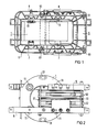
- Fig. 1 die Seitenansicht einer Ventildrossel,
- Fig. 2 die Draufsicht auf die Ventildrossel gemäß Fig.1 mit zur Verdeutlichung teilweise ausgebrochenem Spannrahmen,
- Fig. 3 eine stirnseitige, teilweise geschnittene Draufsicht auf einen die Primär- und Sekundärwicklung sowie deren Kühlrohre enthaltenen, über den einen Schenkel des Drosselkerns in allseitigem Abstand übergesteckten Vergußblock;
- Fig. 4 die teilweise geschnittene Seitenansicht der Anordnung gemäß Fig.3.
- 1 is a side view of a valve throttle,
- 2 shows the top view of the valve throttle according to FIG. 1 with the clamping frame partially broken away for clarification,
- 3 shows an end view, partially in section, of a top view of a casting block which contains the primary and secondary windings and their cooling tubes and is pushed over the one leg of the choke core at a distance on all sides;
- 4 shows the partially sectioned side view of the arrangement according to FIG. 3.
In einem verrippten Kunststoff-Spannrahmen 6 sind als wesentlichste Teile der Ventildrossel ein SchnittbandDrosselkern 5 sowie ein Vergußblock 1 gehaltert, in den eine Primärwicklung 2,3 und ein Sekundärwicklung 4 eingegossen sind. Der durch Spannbänder 52 zusammengehaltene doppel-U-förmige Schnittband-Drosselkern 5 ist mittels Zugstangen 51 in dem Spannrahmen 6 gehaltert. Der eine linke Schenkel des Schnittband-Drosselkerns 5 wird berührungslos von dem Vergußblock 1 umfaßt, in der die Primärwicklung 2,3 und die Sekundärwicklung 4 eingegossen sind. Der Vergußblock 1 ist über Aufnahmen freitragend zum linken Schenkel des Schnittband Drosselkerns 5 in dem Spannrahmen 6 gelagert. Als untere Aufnahmen dienen Gummipuffer 7, während als obere Aufnahmen in den Vergußblock 1 trichterförmige Vertiefungen 11 eingegossen sind, in die Stiftschrauben 8 eingreifen, deren Eindringtiefe gegenüber dem Spannrahmen 6 verstellbar und nach Erreichen der gewünschten Einstelltiefe fixierbar ist.In a ribbed
Wie insbes. aus Fig.3,4 ersichtlich, ist die Primärwicklung 2,3 der Drosselspule zweilagig gewickelt mit einem ersten Wicklungsteil 2 mit dem äußeren Anschluß 21 und und einem dazu konzentrischen zweiten inneren, Wicklungsteil 3 mit einem äußeren Anschluß 31 sowie einem Kernpotentialmittenanschluß M in der Wicklungsmitte, d.h.im Übergangsbereich von dem äußeren ersten Wicklungsteil 2 zum inneren zweiten Wicklungsteil 3. Eine einlagige Sekundärwicklung 4 ragt mit ihren äußeren Anschlüssen 41,42 aus dem Vergußblock 1 heraus. Zur Kühlung der Primärwicklung 2,3 dient ein wasserdurchflossenes EdelstahlKühlrohr 9 mit den äußeren Anschlüssen 91,92; zur besseren Wärmekontaktierung zwischen dem Kühlrohr 9 und der zweckmäßigerweise in Form eines hochkant gewickelten Kupfer-Hohlprofilleiters umgebenden Sekundärwicklung 2,3 ist der Zwischenraum zwischen dem Kühlrohr 9 und der Primärwicklung - wie aus dem Teilschnitt im linken Teil der Fig.2 ersichtlich - ebenfalls mit einer Vergußmasse 10 ausgefüllt. Anstelle des hier vorgesehenen Vergießens des Kühlrohrs innerhalb der vorzugsweise als Hohlprofil mit innerhalb des Hohlprofils verlaufendem Kühlrohr ausgebildeten Primärwicklung kann auch durch ein Druckaufweiten des Kühlrohrs oder durch ein Aufschrumpfen des Hohlprofils auf das Kühlrohr dafür gesorgt werden, daß dies in besonders gutem Wärmekontakt zur Primärwicklung steht.As can be seen in particular from FIG. 3, 4, the
Wie aus Fig.2 ersichtlich, ist der von dem Vergußblock 1 umfaßte Schenkel des Schnittband-Drosselkerns 5 in allseitig berührungslosem Abstand zum Vergußblock 1 gehalten, so daß im Vergleich zu sonst üblichen, auf dem Drosselkern verkeilten Wicklungen bei gleichen Baumaßen eine wesentlich höhere Sicherheit gegenüber Teilentladungen besteht oder bei gleichbleibend guter Verhütung von Teilentladungen der Drosselmodul wesentlich kompakter gebaut werden kann.As can be seen from FIG. 2, the leg of the cutting
Claims (6)
Priority Applications (1)
| Application Number | Priority Date | Filing Date | Title |
|---|---|---|---|
| AT86112961T ATE45438T1 (en) | 1985-10-01 | 1986-09-19 | VALVE CHOKE, ESPECIALLY FOR HIGH VOLTAGE DIRECT TRANSMISSION SYSTEMS. |
Applications Claiming Priority (2)
| Application Number | Priority Date | Filing Date | Title |
|---|---|---|---|
| DE3535018 | 1985-10-01 | ||
| DE3535018 | 1985-10-01 |
Publications (2)
| Publication Number | Publication Date |
|---|---|
| EP0223954A1 true EP0223954A1 (en) | 1987-06-03 |
| EP0223954B1 EP0223954B1 (en) | 1989-08-09 |
Family
ID=6282479
Family Applications (1)
| Application Number | Title | Priority Date | Filing Date |
|---|---|---|---|
| EP86112961A Expired EP0223954B1 (en) | 1985-10-01 | 1986-09-19 | Inductance for a controlled rectifier, particularly for high voltage direct current transmission installations |
Country Status (6)
| Country | Link |
|---|---|
| US (1) | US4775848A (en) |
| EP (1) | EP0223954B1 (en) |
| JP (1) | JPS6286706A (en) |
| AT (1) | ATE45438T1 (en) |
| DE (1) | DE3664973D1 (en) |
| IN (1) | IN163747B (en) |
Cited By (2)
| Publication number | Priority date | Publication date | Assignee | Title |
|---|---|---|---|---|
| EP0459326A1 (en) * | 1990-06-01 | 1991-12-04 | ABBPATENT GmbH | Liquid cooled choke coil |
| US5682292A (en) * | 1993-05-10 | 1997-10-28 | Siemens Aktiengesellschaft | Liquid-cooled valve reactor |
Citations (10)
| Publication number | Priority date | Publication date | Assignee | Title |
|---|---|---|---|---|
| US2264057A (en) * | 1940-08-21 | 1941-11-25 | Gen Electric | Coil support for electrical induction apparatus |
| GB630353A (en) * | 1947-09-18 | 1949-10-11 | Gen Electric Co Ltd | Improvements in or relating to electric inductances |
| US2579522A (en) * | 1946-02-04 | 1951-12-25 | Ohio Crankshaft Co | Transformer construction |
| US2699531A (en) * | 1950-09-02 | 1955-01-11 | Bendix Aviat Corp | Transformer core mounting |
| DE1137148B (en) * | 1959-11-04 | 1962-09-27 | Siemens Ag | Holding device for ring core pairs, preferably for magnetic amplifiers |
| FR2106643A5 (en) * | 1970-09-18 | 1972-05-05 | Anvar | High tension power supply - for linear accelerator ion source |
| DE2554142A1 (en) * | 1975-11-28 | 1977-06-02 | Siemens Ag | ARRANGEMENT WITH INDUCTIVE VOLTAGE CONVERTERS |
| DE2642111A1 (en) * | 1976-09-18 | 1978-03-23 | Bosch Gmbh Robert | Disc shaped power transformer - has multiturn primary winding and single turn secondary winding, with coolant flowing through both windings |
| EP0050432A1 (en) * | 1980-10-03 | 1982-04-28 | Ford Motor Company Limited | Transformer |
| DE3404457A1 (en) * | 1984-02-08 | 1985-08-08 | Siemens AG, 1000 Berlin und 8000 München | DEVICE FOR COOLING A MAGNETIC SYSTEM |
Family Cites Families (11)
| Publication number | Priority date | Publication date | Assignee | Title |
|---|---|---|---|---|
| US3258728A (en) * | 1966-06-28 | Electrical coil and lead wire assembly | ||
| US1471096A (en) * | 1919-05-08 | 1923-10-16 | Gen Electric | Electrical apparatus |
| US1789229A (en) * | 1929-03-09 | 1931-01-13 | Wired Radio Inc | Inductance coil |
| US2413195A (en) * | 1942-12-21 | 1946-12-24 | Pacific Electric Mfg Corp | High potential current transformer means |
| US2464029A (en) * | 1945-04-07 | 1949-03-08 | Gen Electric | Method of making transformers |
| US2988715A (en) * | 1958-09-02 | 1961-06-13 | Zenith Radio Corp | Sweep transformer |
| FR1564935A (en) * | 1968-03-15 | 1969-04-25 | ||
| DE2133987C3 (en) * | 1971-07-08 | 1974-04-25 | Aeg-Elotherm Gmbh, 5630 Remscheidhasten | Medium frequency power transformer with a single-turn secondary winding |
| GB1470902A (en) * | 1975-02-28 | 1977-04-21 | Tioxide Group Ltd | Electrical series reactor |
| DE2554143A1 (en) * | 1975-11-28 | 1977-06-02 | Siemens Ag | VOLTAGE CONVERTER FOR HIGH VOLTAGES |
| DE3100419C2 (en) * | 1981-01-09 | 1986-07-17 | ANT Nachrichtentechnik GmbH, 7150 Backnang | High power density transformer |
-
1986
- 1986-07-31 IN IN583/CAL/86A patent/IN163747B/en unknown
- 1986-09-19 DE DE8686112961T patent/DE3664973D1/en not_active Expired
- 1986-09-19 EP EP86112961A patent/EP0223954B1/en not_active Expired
- 1986-09-19 AT AT86112961T patent/ATE45438T1/en not_active IP Right Cessation
- 1986-09-29 JP JP61231085A patent/JPS6286706A/en active Pending
- 1986-09-30 US US06/913,812 patent/US4775848A/en not_active Expired - Fee Related
Patent Citations (10)
| Publication number | Priority date | Publication date | Assignee | Title |
|---|---|---|---|---|
| US2264057A (en) * | 1940-08-21 | 1941-11-25 | Gen Electric | Coil support for electrical induction apparatus |
| US2579522A (en) * | 1946-02-04 | 1951-12-25 | Ohio Crankshaft Co | Transformer construction |
| GB630353A (en) * | 1947-09-18 | 1949-10-11 | Gen Electric Co Ltd | Improvements in or relating to electric inductances |
| US2699531A (en) * | 1950-09-02 | 1955-01-11 | Bendix Aviat Corp | Transformer core mounting |
| DE1137148B (en) * | 1959-11-04 | 1962-09-27 | Siemens Ag | Holding device for ring core pairs, preferably for magnetic amplifiers |
| FR2106643A5 (en) * | 1970-09-18 | 1972-05-05 | Anvar | High tension power supply - for linear accelerator ion source |
| DE2554142A1 (en) * | 1975-11-28 | 1977-06-02 | Siemens Ag | ARRANGEMENT WITH INDUCTIVE VOLTAGE CONVERTERS |
| DE2642111A1 (en) * | 1976-09-18 | 1978-03-23 | Bosch Gmbh Robert | Disc shaped power transformer - has multiturn primary winding and single turn secondary winding, with coolant flowing through both windings |
| EP0050432A1 (en) * | 1980-10-03 | 1982-04-28 | Ford Motor Company Limited | Transformer |
| DE3404457A1 (en) * | 1984-02-08 | 1985-08-08 | Siemens AG, 1000 Berlin und 8000 München | DEVICE FOR COOLING A MAGNETIC SYSTEM |
Cited By (2)
| Publication number | Priority date | Publication date | Assignee | Title |
|---|---|---|---|---|
| EP0459326A1 (en) * | 1990-06-01 | 1991-12-04 | ABBPATENT GmbH | Liquid cooled choke coil |
| US5682292A (en) * | 1993-05-10 | 1997-10-28 | Siemens Aktiengesellschaft | Liquid-cooled valve reactor |
Also Published As
| Publication number | Publication date |
|---|---|
| DE3664973D1 (en) | 1989-09-14 |
| ATE45438T1 (en) | 1989-08-15 |
| EP0223954B1 (en) | 1989-08-09 |
| US4775848A (en) | 1988-10-04 |
| IN163747B (en) | 1988-11-05 |
| JPS6286706A (en) | 1987-04-21 |
Similar Documents
| Publication | Publication Date | Title |
|---|---|---|
| DE19515003C2 (en) | Superconducting coil | |
| DE10304606B3 (en) | Transformer providing high electrical currents e.g. for magnetization of magnets or magnetic field deformation, has secondary provided by electrically-conductive plate divided by slit to providing current terminals | |
| EP0698277B1 (en) | Liquid-cooled valve choke | |
| DE3718383A1 (en) | HIGH FREQUENCY POWER TRANSMITTER | |
| EP0557549B1 (en) | Toroidal core transformer | |
| EP1423903B1 (en) | Electric motor comprising a cooling system | |
| EP0223954B1 (en) | Inductance for a controlled rectifier, particularly for high voltage direct current transmission installations | |
| DE4008417C2 (en) | Device for connecting the electrical connections of capacitors | |
| DE2926403A1 (en) | Thyristor or diode cooling device - has glass fibre reinforced plastics springs to clamp semiconductor device between heat dissipating blocks | |
| EP0459326A1 (en) | Liquid cooled choke coil | |
| EP1554741B1 (en) | Insulant housing comprising an inner ribbed contour | |
| DE2417125B2 (en) | Power transformer | |
| EP0124809B1 (en) | Inductive element | |
| DE19723958C2 (en) | Tension bandage | |
| EP3721458B1 (en) | Electric device with pressing plates for clamping a magnetizable core | |
| EP0932168A2 (en) | Coaxial transformer | |
| DE2836283C2 (en) | Electrical device winding | |
| DE19627817A1 (en) | Pancake coil electronic component | |
| EP0166952B1 (en) | High-current transformer with indirect adjustment of tension by an intermediate circuit | |
| DE4008424C2 (en) | ||
| DE2544275A1 (en) | Liq. cooled induction choke coil - has hollow conductor with galvanic end connection, and concentric inner conductor | |
| DE3040412C2 (en) | Winding arrangement for transformers | |
| EP0053691A1 (en) | Choke for high current transformers | |
| DE2710112A1 (en) | Current transformer with two shaft components - has annular component with iron transformer core passing through central aperture | |
| EP0887906A1 (en) | Electrical machine with copper rod conductors |
Legal Events
| Date | Code | Title | Description |
|---|---|---|---|
| PUAI | Public reference made under article 153(3) epc to a published international application that has entered the european phase |
Free format text: ORIGINAL CODE: 0009012 |
|
| 17P | Request for examination filed |
Effective date: 19870407 |
|
| AK | Designated contracting states |
Kind code of ref document: A1 Designated state(s): AT CH DE FR GB IT LI SE |
|
| 17Q | First examination report despatched |
Effective date: 19881107 |
|
| GRAA | (expected) grant |
Free format text: ORIGINAL CODE: 0009210 |
|
| AK | Designated contracting states |
Kind code of ref document: B1 Designated state(s): AT CH DE FR GB IT LI SE |
|
| REF | Corresponds to: |
Ref document number: 45438 Country of ref document: AT Date of ref document: 19890815 Kind code of ref document: T |
|
| PGFP | Annual fee paid to national office [announced via postgrant information from national office to epo] |
Ref country code: AT Payment date: 19890825 Year of fee payment: 4 |
|
| PGFP | Annual fee paid to national office [announced via postgrant information from national office to epo] |
Ref country code: SE Payment date: 19890912 Year of fee payment: 4 |
|
| REF | Corresponds to: |
Ref document number: 3664973 Country of ref document: DE Date of ref document: 19890914 |
|
| PGFP | Annual fee paid to national office [announced via postgrant information from national office to epo] |
Ref country code: FR Payment date: 19890928 Year of fee payment: 4 |
|
| ET | Fr: translation filed | ||
| ITF | It: translation for a ep patent filed |
Owner name: STUDIO JAUMANN |
|
| GBT | Gb: translation of ep patent filed (gb section 77(6)(a)/1977) | ||
| PGFP | Annual fee paid to national office [announced via postgrant information from national office to epo] |
Ref country code: DE Payment date: 19891127 Year of fee payment: 4 |
|
| PGFP | Annual fee paid to national office [announced via postgrant information from national office to epo] |
Ref country code: CH Payment date: 19891218 Year of fee payment: 4 |
|
| PLBE | No opposition filed within time limit |
Free format text: ORIGINAL CODE: 0009261 |
|
| STAA | Information on the status of an ep patent application or granted ep patent |
Free format text: STATUS: NO OPPOSITION FILED WITHIN TIME LIMIT |
|
| 26N | No opposition filed | ||
| PG25 | Lapsed in a contracting state [announced via postgrant information from national office to epo] |
Ref country code: GB Effective date: 19900919 Ref country code: AT Effective date: 19900919 |
|
| PG25 | Lapsed in a contracting state [announced via postgrant information from national office to epo] |
Ref country code: SE Effective date: 19900920 |
|
| ITTA | It: last paid annual fee | ||
| PG25 | Lapsed in a contracting state [announced via postgrant information from national office to epo] |
Ref country code: LI Effective date: 19900930 Ref country code: CH Effective date: 19900930 |
|
| GBPC | Gb: european patent ceased through non-payment of renewal fee | ||
| PG25 | Lapsed in a contracting state [announced via postgrant information from national office to epo] |
Ref country code: FR Effective date: 19910530 |
|
| REG | Reference to a national code |
Ref country code: CH Ref legal event code: PL |
|
| PG25 | Lapsed in a contracting state [announced via postgrant information from national office to epo] |
Ref country code: DE Effective date: 19910601 |
|
| REG | Reference to a national code |
Ref country code: FR Ref legal event code: ST |
|
| EUG | Se: european patent has lapsed |
Ref document number: 86112961.7 Effective date: 19910527 |
|
| PG25 | Lapsed in a contracting state [announced via postgrant information from national office to epo] |
Ref country code: IT Free format text: LAPSE BECAUSE OF NON-PAYMENT OF DUE FEES;WARNING: LAPSES OF ITALIAN PATENTS WITH EFFECTIVE DATE BEFORE 2007 MAY HAVE OCCURRED AT ANY TIME BEFORE 2007. THE CORRECT EFFECTIVE DATE MAY BE DIFFERENT FROM THE ONE RECORDED. Effective date: 20050919 |