EP0223912A1 - Device for cooling hot dust-laden gases - Google Patents
Device for cooling hot dust-laden gases Download PDFInfo
- Publication number
- EP0223912A1 EP0223912A1 EP86109914A EP86109914A EP0223912A1 EP 0223912 A1 EP0223912 A1 EP 0223912A1 EP 86109914 A EP86109914 A EP 86109914A EP 86109914 A EP86109914 A EP 86109914A EP 0223912 A1 EP0223912 A1 EP 0223912A1
- Authority
- EP
- European Patent Office
- Prior art keywords
- tubes
- tube
- insert
- walls
- bundle
- Prior art date
- Legal status (The legal status is an assumption and is not a legal conclusion. Google has not performed a legal analysis and makes no representation as to the accuracy of the status listed.)
- Granted
Links
- 239000007789 gas Substances 0.000 title claims abstract description 15
- 238000001816 cooling Methods 0.000 title claims abstract description 8
- 238000010438 heat treatment Methods 0.000 description 3
- 230000005855 radiation Effects 0.000 description 3
- XEEYBQQBJWHFJM-UHFFFAOYSA-N Iron Chemical compound [Fe] XEEYBQQBJWHFJM-UHFFFAOYSA-N 0.000 description 2
- 238000002309 gasification Methods 0.000 description 2
- 210000000078 claw Anatomy 0.000 description 1
- 229910052742 iron Inorganic materials 0.000 description 1
- XLYOFNOQVPJJNP-UHFFFAOYSA-N water Substances O XLYOFNOQVPJJNP-UHFFFAOYSA-N 0.000 description 1
Images


Classifications
-
- F—MECHANICAL ENGINEERING; LIGHTING; HEATING; WEAPONS; BLASTING
- F28—HEAT EXCHANGE IN GENERAL
- F28D—HEAT-EXCHANGE APPARATUS, NOT PROVIDED FOR IN ANOTHER SUBCLASS, IN WHICH THE HEAT-EXCHANGE MEDIA DO NOT COME INTO DIRECT CONTACT
- F28D7/00—Heat-exchange apparatus having stationary tubular conduit assemblies for both heat-exchange media, the media being in contact with different sides of a conduit wall
- F28D7/005—Heat-exchange apparatus having stationary tubular conduit assemblies for both heat-exchange media, the media being in contact with different sides of a conduit wall the conduits for only one medium being tubes having bent portions or being assembled from bent tubes or being tubes having a toroidal configuration
-
- C—CHEMISTRY; METALLURGY
- C10—PETROLEUM, GAS OR COKE INDUSTRIES; TECHNICAL GASES CONTAINING CARBON MONOXIDE; FUELS; LUBRICANTS; PEAT
- C10J—PRODUCTION OF PRODUCER GAS, WATER-GAS, SYNTHESIS GAS FROM SOLID CARBONACEOUS MATERIAL, OR MIXTURES CONTAINING THESE GASES; CARBURETTING AIR OR OTHER GASES
- C10J3/00—Production of combustible gases containing carbon monoxide from solid carbonaceous fuels
- C10J3/72—Other features
- C10J3/86—Other features combined with waste-heat boilers
-
- C—CHEMISTRY; METALLURGY
- C10—PETROLEUM, GAS OR COKE INDUSTRIES; TECHNICAL GASES CONTAINING CARBON MONOXIDE; FUELS; LUBRICANTS; PEAT
- C10K—PURIFYING OR MODIFYING THE CHEMICAL COMPOSITION OF COMBUSTIBLE GASES CONTAINING CARBON MONOXIDE
- C10K1/00—Purifying combustible gases containing carbon monoxide
- C10K1/04—Purifying combustible gases containing carbon monoxide by cooling to condense non-gaseous materials
-
- F—MECHANICAL ENGINEERING; LIGHTING; HEATING; WEAPONS; BLASTING
- F22—STEAM GENERATION
- F22B—METHODS OF STEAM GENERATION; STEAM BOILERS
- F22B1/00—Methods of steam generation characterised by form of heating method
- F22B1/02—Methods of steam generation characterised by form of heating method by exploitation of the heat content of hot heat carriers
- F22B1/18—Methods of steam generation characterised by form of heating method by exploitation of the heat content of hot heat carriers the heat carrier being a hot gas, e.g. waste gas such as exhaust gas of internal-combustion engines
- F22B1/1838—Methods of steam generation characterised by form of heating method by exploitation of the heat content of hot heat carriers the heat carrier being a hot gas, e.g. waste gas such as exhaust gas of internal-combustion engines the hot gas being under a high pressure, e.g. in chemical installations
- F22B1/1846—Methods of steam generation characterised by form of heating method by exploitation of the heat content of hot heat carriers the heat carrier being a hot gas, e.g. waste gas such as exhaust gas of internal-combustion engines the hot gas being under a high pressure, e.g. in chemical installations the hot gas being loaded with particles, e.g. waste heat boilers after a coal gasification plant
-
- F—MECHANICAL ENGINEERING; LIGHTING; HEATING; WEAPONS; BLASTING
- F28—HEAT EXCHANGE IN GENERAL
- F28F—DETAILS OF HEAT-EXCHANGE AND HEAT-TRANSFER APPARATUS, OF GENERAL APPLICATION
- F28F9/00—Casings; Header boxes; Auxiliary supports for elements; Auxiliary members within casings
- F28F9/007—Auxiliary supports for elements
- F28F9/013—Auxiliary supports for elements for tubes or tube-assemblies
-
- F—MECHANICAL ENGINEERING; LIGHTING; HEATING; WEAPONS; BLASTING
- F28—HEAT EXCHANGE IN GENERAL
- F28D—HEAT-EXCHANGE APPARATUS, NOT PROVIDED FOR IN ANOTHER SUBCLASS, IN WHICH THE HEAT-EXCHANGE MEDIA DO NOT COME INTO DIRECT CONTACT
- F28D21/00—Heat-exchange apparatus not covered by any of the groups F28D1/00 - F28D20/00
- F28D2021/0019—Other heat exchangers for particular applications; Heat exchange systems not otherwise provided for
- F28D2021/0075—Other heat exchangers for particular applications; Heat exchange systems not otherwise provided for for syngas or cracked gas cooling systems
-
- Y—GENERAL TAGGING OF NEW TECHNOLOGICAL DEVELOPMENTS; GENERAL TAGGING OF CROSS-SECTIONAL TECHNOLOGIES SPANNING OVER SEVERAL SECTIONS OF THE IPC; TECHNICAL SUBJECTS COVERED BY FORMER USPC CROSS-REFERENCE ART COLLECTIONS [XRACs] AND DIGESTS
- Y10—TECHNICAL SUBJECTS COVERED BY FORMER USPC
- Y10S—TECHNICAL SUBJECTS COVERED BY FORMER USPC CROSS-REFERENCE ART COLLECTIONS [XRACs] AND DIGESTS
- Y10S165/00—Heat exchange
- Y10S165/355—Heat exchange having separate flow passage for two distinct fluids
- Y10S165/40—Shell enclosed conduit assembly
- Y10S165/401—Shell enclosed conduit assembly including tube support or shell-side flow director
Definitions
- the invention relates to a device for cooling hot, pressurized, dust-laden gases with the features of the preamble of claim 1.
- Such a device designed as a radiation cooler is known from DE-OS 32 08 421 and is used for cooling the gases leaving a gasification reactor.
- the flat tube walls ensure intensive cooling of the gases.
- the radiation cooler is followed by a separate convection cooler with bundle heating surfaces.
- the invention has for its object to design the heating surfaces of the generic device so that a compact cooling device is created.
- the tube bundle serving as a convection heating surface By arranging the tube bundle serving as a convection heating surface within the radiation cooler, the gas can be cooled in a short way.
- the direct continuation of a flat tube wall in the tube bundle enables a compact design of the cooling device.
- the cooler shown is used to cool hot, pressurized and dust-laden gases, especially those that are generated in a gasification reactor.
- the cooler consists essentially of two components, namely a standing pressure vessel 1, which has the task of absorbing the pressure of the gas, for example from 20 to 25 bar, and of the internals which act as heat exchangers.
- the internals consist of an insert 2, flat tube walls 3 (bulkhead walls), a first tube bundle 4 and, if appropriate, a second tube bundle 5 or further tube bundles.
- the pressure vessel 1 consists of several cylindrical segment rings welded together. It is closed by an upper and a lower cover 6, 7.
- the upper cover 6 is provided with a gas inlet connection 8 and the lower cover with a gas outlet connection 9.
- a screwable flange connection 10 is inserted in the upper part of the pressure vessel 1 in order to ensure easy opening of the pressure vessel 1.
- the pressure vessel 1 can be parked in a scaffold with the help of claws.
- the insert 2 is arranged at a distance from the inner wall of the pressure vessel 1 and is connected to the gas inlet connection 8 in such a way that the gas to be cooled which flows in flows through the insert 2 in the longitudinal direction.
- the outlet end of the insert 2 is open, so that pressure equalization can take place between the interior of the insert 2 and the annular space between the insert 2 and the pressure vessel 1.
- the insert 2 is formed from gas-tight, welded, cooled pipes which are connected to an inlet header 11 located in the lower part and to an outlet header 12 located in the upper part.
- the tubes of insert 2 are flowed through from bottom to top and connected as an evaporator.
- the flat tube walls 3 are arranged within the insert 2 and run in the longitudinal direction of the pressure vessel 1 and parallel to one another.
- the tubes 13, 14 of the tube walls 3 are connected to one another via flat iron and are each connected to an inlet header 16 and an outlet header 17.
- the feed lines to the inlet manifolds 11, 16 of the tube walls 3 and the insert 2 are passed through the annular space between the insert 2 and the pressure vessel 1.
- the tube walls 3, like the insert 2, are connected as evaporators and flowed through from bottom to top.
- the tubes of at least one of the tube walls 3, preferably the middle tube wall, are bent out to form the first tube bundle 4, which extends in several turns over the cross section of the insert 2.
- the first tube bundle 4 is connected as an evaporator.
- a pipe 14 is bent out of the plane of the pipe wall 3 from three neighboring pipes (FIG. 3).
- alleys 18 are formed within the tube walls 3, through which the tubes of the tube bundle 4 are passed.
- the tubes 13 are connected to one another on both sides of the lanes 18 by a web 19.
- the tubes of the tube bundle 4 are passed through this web 19 and are thus carried.
- the tubes of the tube bundle 4 can also be surrounded by a welded-on sleeve.
- the tubes 13 of the tube walls 3 remaining on the wall plane on both sides of the middle tube wall 3 thus serve as support tubes, while the tubes 14 of these tube walls and the tubes 20 of the other tube walls are guided as loose tubes.
- a second tube bundle 5 or further tube bundles can be provided within the insert 2.
- the second tube bundle 5 can be connected as a superheater, feed water preheater or as an additional evaporator.
- the second tube bundle 5 is guided through the tube walls 3 in the same way as the first tube bundle 4 and carried by these.
- the second tube bundle 5 is connected to an inlet header 21 and an outlet header 22.
- the tubes of the middle tube wall 3 are alternately bent out to the right and left and serve to hold the collectors 21, 22.
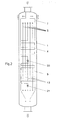
- the cooler shown in FIG. 3 has a gas inlet connection 8 connected to the lower cover 7 and a gas outlet connection 9 connected to the upper cover 6.
- the tube bundle 4 has been moved into the upper part of the insert 2. Otherwise, this cooler corresponds to the cooler according to FIG. 1. In such a cooler, the incrustations removed from the tube walls 3 can be removed from the cooler in a simpler manner.
Landscapes
- Engineering & Computer Science (AREA)
- Chemical & Material Sciences (AREA)
- Combustion & Propulsion (AREA)
- Mechanical Engineering (AREA)
- General Engineering & Computer Science (AREA)
- Physics & Mathematics (AREA)
- Thermal Sciences (AREA)
- Oil, Petroleum & Natural Gas (AREA)
- Organic Chemistry (AREA)
- Chemical Kinetics & Catalysis (AREA)
- General Chemical & Material Sciences (AREA)
- Life Sciences & Earth Sciences (AREA)
- Sustainable Development (AREA)
- Sustainable Energy (AREA)
- Heat-Exchange Devices With Radiators And Conduit Assemblies (AREA)
Abstract
Zum Kühlen von heißen, unter Druck stehenden, staubbeladenen Gasen wird eine Vorrichtung verwendet, die aus einem aus gekühlten Rohren gebildeten und innerhalb eines Druckbehälters (1) angeordneten Einsatz (2) besteht. In dem Einsatz (2) sind mehrere ebene Rohrwände (3) vorgesehen, die parallel zur Längsachse des Einsatzes (2) verlaufen. Mindestens eine der ebenen Rohrwände (3) ist zu einem Rohrbündel (4) ausgebogen,das sich über den Querschnitt des Einsatzes (2) erstreckt. Die Rohre des Rohrbündels (4) sind durch die übrigen Rohrwände (3) hindurchgeführt und werden von diesen getragen. 
Description
Die Erfindung betrifft eine Vorrichtung zum Kühlen von heißen, unter Druck stehenden, staubbeladenen Gasen mit den Merkmalen des Oberbegriffes des Patentanspruches 1.The invention relates to a device for cooling hot, pressurized, dust-laden gases with the features of the preamble of
Eine solche als Strahlungskühler ausgebildete Vorrichtung ist aus der DE-OS 32 08 421 bekannt und dient der Abkühlung der einen Vergasungsreaktor verlassenden Gase. Dabei sorgen die ebenen Rohrwände für eine intensive Kühlung der Gase. Bei der bekannten Vorrichtung ist dem Strahlungskühler ein getrennter Konvektionskühler mit Bündelheizflächen nachgeschaltet.Such a device designed as a radiation cooler is known from DE-OS 32 08 421 and is used for cooling the gases leaving a gasification reactor. The flat tube walls ensure intensive cooling of the gases. In the known device, the radiation cooler is followed by a separate convection cooler with bundle heating surfaces.
Der Erfindung liegt die Aufgabe zugrunde, die Heizflächen der gattungsgemäßen Vorrichtung so zugestalten, daß eine kompakte Kühleinrichtung entsteht.The invention has for its object to design the heating surfaces of the generic device so that a compact cooling device is created.
Diese Aufgabe wird bei einer gattungsgemäßen Vorrichtung durch die kennzeichnenden Merkmale des Patentanspruches 1 gelöst. Vorteilhafte Ausgestaltungen der Erfindung sind in den Unteransprüchen angegeben.This object is achieved in a generic device by the characterizing features of
Durch die Anordnung des als Konvektionsheizfläche dienenden Rohrbündels innerhalb des Strahlungskühlers kann das Gas auf kurzem Weg gekühlt werden. Die unmittelbare Fortführung der einen ebenen Rohrwand in das Rohrbündel ermöglicht eine kompakte Bauweise der Kühlvorrichtung.By arranging the tube bundle serving as a convection heating surface within the radiation cooler, the gas can be cooled in a short way. The direct continuation of a flat tube wall in the tube bundle enables a compact design of the cooling device.
Mehrere Ausführungsbeispiele der Erfindung sind in der Zeichnung dargestellt und werden im folgenden näher erläutert. Es zeigen:
- Fig. 1 schematisch einen Längsschnitt durch eine Vorrichtung gemäß der Erfindung,
- Fig. 2 und 3 ebenfalls im Längsschnitt eine andere Ausführungsform der Erfindung,
- Fig. 4 den Schnitt IV - IV nach Fig. 1 und
- Fig. 5 die Einzelheit Z nach Fig. 1.
- 1 schematically shows a longitudinal section through a device according to the invention,
- 2 and 3 also in longitudinal section another embodiment of the invention,
- Fig. 4 shows the section IV - IV of Fig. 1 and
- 5 shows the detail Z according to FIG. 1.
Der dargestellte Kühler dient zur Abkühlung von heißen, unter Druck stehenden und mit Staub beladenen Gasen insbesondere von solchen, die in einem Vergasungsreaktor erzeugt sind. Der Kühler besteht im wesentlichen aus zwei Bauteilen, nämlich einem stehenden Druckbehälter 1, der die Aufgabe hat, den Druck des Gases von beispielsweise 20 bis 25 bar aufzunehmen und aus den Einbauten, die als Wärmeüberträger fungieren. Die Einbauten setzen sich aus einem Einsatz 2, ebenen Rohrwänden 3 (Schottenwände), einem ersten Rohrbündel 4 und gegebenenfalls einen zweiten Rohrbündel 5 oder weiteren Rohrbündeln zusammen.The cooler shown is used to cool hot, pressurized and dust-laden gases, especially those that are generated in a gasification reactor. The cooler consists essentially of two components, namely a standing
Der Druckbehälter 1 besteht aus mehreren zylindrischen, miteinander verschweißten Segmentringen. Er ist durch einen oberen und einen unteren Deckel 6, 7 verschlossen. Der obere Deckel 6 ist mit einem Gaseintrittsstutzen 8 und der untere Deckel mit einem Gasaustrittsstutzen 9 versehen. Im oberen Teil des Druckbehälters 1 ist eine schraubbare Flanschverbindung 10 eingefügt, um ein einfaches Öffnen des Druckbehälters 1 zu gewährleisten. Der Druckbehälter 1 kann mit Hilfe von Pratzen in einem Gerüst abgestellt werden.The
Der Einsatz 2 ist mit Abstand von der Innenwand der Druckbehälters 1 angeordnet und so mit dem Gaseintrittsstutzen 8 verbunden, daß das eintretende, zu kühlende Gas den Einsatz 2 in Längsrichtung durchströmt. Das Austrittsende des Einsatzes 2 ist offen, so daß ein Druckausgleich zwischen den Innenraum des Einsatzes 2 und dem Ringraum zwischen dem Einsatz 2 und dem Druckbehälter 1 stattfinden kann.The
Der Einsatz 2 ist aus gasdicht miteinander verschweißten, gekühlten Rohren gebildet, die an einen im unteren Teil liegenden Eintrittssammler 11 und an einen im oberen Teil liegenden Austrittssammler 12 angeschlossen sind. Die Rohre des Einsatzes 2 sind von unten nach oben durchströmt und als verdampfer geschaltet.The
Die ebenen Rohrwände 3 sind innerhalb des Einsatzes 2 angeordnet und verlaufen in Längsrichtung des Druckbehälters 1 und parallel zueinander. Die Rohre 13, 14 der Rohrwände 3 sind über Flacheisen miteinander verbunden und jeweils an einen Eintrittssammler 16 und einen Austrittssammler 17 angeschlossen. Die Zuleitungen zu den Eintrittssammlern 11, 16 der Rohrwände 3 und des Einsatzes 2 sind durch den Ringraum zwischen dem Einsatz 2 und dem Druckbehälter 1 hindurchgeführt. Die Rohrwände 3 sind ebenso wie der Einsatz 2 als Verdampfer geschaltet und von unten nach oben durchströmt.The
Die Rohre mindestens einer der Rohrwände 3, vorzugsweise der mittleren Rohrwand sind zu dem ersten Rohrbündel 4 ausgebogen, das sich in mehreren Windungen über den Querschnitt des Einsatzes 2 erstreckt. Aus Gründen der Übersichtlichkeit ist in den Figuren 1 und 2 ein einflutiges Rohrbündel dargestellt. Es ist aber ebenso ein mehrflutiges Rohrbündel möglich. Das erste Rohrbündel 4 ist als Verdampfer geschaltet.The tubes of at least one of the
In dem Bereich der übrigen, nicht ausgebogenen Rohrwände 3 ist von jeweils drei benachbarten Rohren ein Rohr 14 aus der Ebene der Rohrwand 3 herausgebogen (Fig. 3). Auf diese Weise sind Gassen 18 innerhalb der Rohrwände 3 gebildet, durch die die Rohre des Rohrbündels 4 hindurchgeführt sind. In den der mittleren Rohrwand unmittelbar benachbarten Rohrwänden 3 sind die Rohre 13 beiderseits der Gassen 18 durch einen Steg 19 miteinander verbunden. Durch diesen Steg 19 werden die Rohre des Rohrbündels 4 hindurchgeführt und damit getragen. Im Bereich des Durchtrittes durch den Steg 19 können die Rohre des Rohrbündels 4 auch von einer aufgeschweißten Hülse umgeben sein. Die in der Wandebene verbleibenden Rohre 13 der Rohrwände 3 beiderseits der mittleren Rohrwand 3 dienen somit als Tragrohre, während die Rohre 14 dieser Rohrwände und die Rohre 20 der übrigen Rohrwände als lose Rohre geführt werden.In the area of the remaining, not
Innerhalb des Einsatzes 2 kann - wie in Fig. 2 dargestellt ist - ein zweites Rohrbündel 5 oder weitere Rohrbündel vorgesehen werden. Das zweite Rohrbündel 5 kann als Überhitzer, Speisewasservorwärmer oder als zusätzlicher Verdampfer geschaltet sein. Das zweite Rohrbündel 5 ist in gleicher Weise wie das erste Rohrbündel 4 durch die Rohrwände 3 hindurchgeführt und von diesen getragen. Das zweite Rohrbündel 5 ist an einen Eintrittssammler 21 und einen Austrittssammler 22 angeschlossen. Im Bereich der Sammler 21, 22 sind die Rohre der mittleren Rohrwand 3 wechselweise nach rechts und links ausgebogen und dienen der Halterung der Sammler 21, 22.As shown in FIG. 2, a
Der in Fig. 3 dargestellte Kühler weist einen an den unteren Deckel 7 angeschlossenen Gaseintrittsstutzen 8 und einen an den oberen Deckel 6 angeschlossenen Gasaustrittsstutzen 9 auf. Dabei ist das Rohrbündel 4 in den oberen Teil des Einsatzes 2 verlegt worden. Im übrigen stimmt dieser Kühler mit dem Kühler gemäß Fig. 1 überein. Bei einem solchen Kühler können die von den Rohrwänden 3 entfernten Verkrustungen in einfacherer Weise aus dem Kühler entfernt werden.The cooler shown in FIG. 3 has a gas inlet connection 8 connected to the
Claims (6)
Applications Claiming Priority (2)
| Application Number | Priority Date | Filing Date | Title |
|---|---|---|---|
| DE3538515 | 1985-10-30 | ||
| DE19853538515 DE3538515A1 (en) | 1985-10-30 | 1985-10-30 | DEVICE FOR COOLING HOT, DUST-LOADED GASES |
Publications (2)
| Publication Number | Publication Date |
|---|---|
| EP0223912A1 true EP0223912A1 (en) | 1987-06-03 |
| EP0223912B1 EP0223912B1 (en) | 1989-04-26 |
Family
ID=6284766
Family Applications (1)
| Application Number | Title | Priority Date | Filing Date |
|---|---|---|---|
| EP86109914A Expired EP0223912B1 (en) | 1985-10-30 | 1986-07-18 | Device for cooling hot dust-laden gases |
Country Status (6)
| Country | Link |
|---|---|
| US (1) | US4727933A (en) |
| EP (1) | EP0223912B1 (en) |
| JP (1) | JPH0781687B2 (en) |
| CN (1) | CN1013877B (en) |
| DE (2) | DE3538515A1 (en) |
| ZA (1) | ZA865717B (en) |
Cited By (3)
| Publication number | Priority date | Publication date | Assignee | Title |
|---|---|---|---|---|
| EP0375894A1 (en) * | 1988-12-30 | 1990-07-04 | Krupp Koppers GmbH | Process and radiation cooler for the radiation cooling of a product gas flow from a gasification reactor |
| WO1991010106A1 (en) * | 1990-01-05 | 1991-07-11 | Burmeister & Wain Energi A/S | Gas cooler for heat transfer by radiation |
| WO1991010107A1 (en) * | 1990-01-05 | 1991-07-11 | Burmeister & Wain Energi A/S | Gas cooler for heat transfer by convection |
Families Citing this family (4)
| Publication number | Priority date | Publication date | Assignee | Title |
|---|---|---|---|---|
| DE4007754C2 (en) * | 1990-03-12 | 1993-12-16 | Gutehoffnungshuette Man | Gas cooler for cooling dust-laden gases |
| JP2544584B2 (en) * | 1994-04-11 | 1996-10-16 | 株式会社日立製作所 | Coal gasifier and method of using coal gasifier |
| CN106987279A (en) * | 2017-05-08 | 2017-07-28 | 哈尔滨工业大学 | A kind of U-shaped coal gasification reaction device of secondary separation slagging-off and the coal gasifying process that secondary separation slagging-off is carried out using the device |
| AU2020296057A1 (en) * | 2019-06-17 | 2021-12-23 | Header-coil Company A/S | Heat exchanger with pipe bundle |
Citations (6)
| Publication number | Priority date | Publication date | Assignee | Title |
|---|---|---|---|---|
| FR1253668A (en) * | 1960-04-08 | 1961-02-10 | Babcock & Wilcox Co | Improvements to tubular heat exchangers |
| GB1094253A (en) * | 1965-02-24 | 1967-12-06 | Babcock & Wilcox Ltd | Improvements in or relating to heat exchanger tube banks |
| GB1117813A (en) * | 1965-02-17 | 1968-06-26 | Babcock & Wilcox Ltd | Improvements in tubulous walls arranged for supporting heat exchange tube banks |
| GB2068095A (en) * | 1980-01-23 | 1981-08-05 | Combustion Eng | Steam generating heat exchanger |
| WO1984000411A1 (en) * | 1982-07-12 | 1984-02-02 | Stork Ketels Mij Tot Expl Van | Vertical radiation tank |
| DE3248096A1 (en) * | 1982-12-24 | 1984-07-05 | M.A.N. Maschinenfabrik Augsburg-Nürnberg AG, 4200 Oberhausen | STANDING DEVICE FOR COOLING GASES UNDER HIGH PRESSURE WITH HIGH DUST |
Family Cites Families (12)
| Publication number | Priority date | Publication date | Assignee | Title |
|---|---|---|---|---|
| US1818446A (en) * | 1930-01-28 | 1931-08-11 | Superheater Co Ltd | Reheater |
| US2033077A (en) * | 1931-04-16 | 1936-03-03 | Babcock & Wilcox Co | Tube support |
| NL240569A (en) * | 1959-05-30 | |||
| CH398183A (en) * | 1962-09-03 | 1965-08-31 | Escher Wyss Ag | Gas heater with parallel combustion chamber tubes that are arranged in a ring |
| US3393665A (en) * | 1966-12-14 | 1968-07-23 | Combustion Eng | Support tie for tubular walls of a furnace and adjacent tube bank |
| AT313934B (en) * | 1971-08-03 | 1974-03-11 | Waagner Biro Ag | Heat exchanger and process for its manufacture |
| US4187902A (en) * | 1971-10-13 | 1980-02-12 | Hercofina | Heat exchange apparatus |
| DE2313438B2 (en) * | 1973-03-17 | 1978-07-20 | Gutehoffnungshuette Sterkrade | Tubular apparatus, in particular steam generators |
| US3967677A (en) * | 1975-05-28 | 1976-07-06 | Mobil Oil Corporation | Heat exchanger baffles |
| DE3208421A1 (en) * | 1982-03-09 | 1983-09-15 | Deutsche Babcock Anlagen Ag, 4200 Oberhausen | DEVICE FOR COOLING A GAS PRODUCED IN A CARBURETOR |
| DE3406893C3 (en) * | 1984-02-25 | 1996-02-08 | Babcock Energie Umwelt | Convection cooler |
| US4624304A (en) * | 1985-11-25 | 1986-11-25 | Combustion Engineering, Inc. | Expandable support for insertion into tube bundle |
-
1985
- 1985-10-30 DE DE19853538515 patent/DE3538515A1/en active Granted
-
1986
- 1986-07-18 DE DE8686109914T patent/DE3663084D1/en not_active Expired
- 1986-07-18 EP EP86109914A patent/EP0223912B1/en not_active Expired
- 1986-07-31 ZA ZA865717A patent/ZA865717B/en unknown
- 1986-08-07 JP JP61186121A patent/JPH0781687B2/en not_active Expired - Lifetime
- 1986-09-03 US US06/903,462 patent/US4727933A/en not_active Expired - Fee Related
- 1986-09-13 CN CN86106039A patent/CN1013877B/en not_active Expired
Patent Citations (6)
| Publication number | Priority date | Publication date | Assignee | Title |
|---|---|---|---|---|
| FR1253668A (en) * | 1960-04-08 | 1961-02-10 | Babcock & Wilcox Co | Improvements to tubular heat exchangers |
| GB1117813A (en) * | 1965-02-17 | 1968-06-26 | Babcock & Wilcox Ltd | Improvements in tubulous walls arranged for supporting heat exchange tube banks |
| GB1094253A (en) * | 1965-02-24 | 1967-12-06 | Babcock & Wilcox Ltd | Improvements in or relating to heat exchanger tube banks |
| GB2068095A (en) * | 1980-01-23 | 1981-08-05 | Combustion Eng | Steam generating heat exchanger |
| WO1984000411A1 (en) * | 1982-07-12 | 1984-02-02 | Stork Ketels Mij Tot Expl Van | Vertical radiation tank |
| DE3248096A1 (en) * | 1982-12-24 | 1984-07-05 | M.A.N. Maschinenfabrik Augsburg-Nürnberg AG, 4200 Oberhausen | STANDING DEVICE FOR COOLING GASES UNDER HIGH PRESSURE WITH HIGH DUST |
Cited By (3)
| Publication number | Priority date | Publication date | Assignee | Title |
|---|---|---|---|---|
| EP0375894A1 (en) * | 1988-12-30 | 1990-07-04 | Krupp Koppers GmbH | Process and radiation cooler for the radiation cooling of a product gas flow from a gasification reactor |
| WO1991010106A1 (en) * | 1990-01-05 | 1991-07-11 | Burmeister & Wain Energi A/S | Gas cooler for heat transfer by radiation |
| WO1991010107A1 (en) * | 1990-01-05 | 1991-07-11 | Burmeister & Wain Energi A/S | Gas cooler for heat transfer by convection |
Also Published As
| Publication number | Publication date |
|---|---|
| ZA865717B (en) | 1987-03-25 |
| DE3538515A1 (en) | 1987-05-07 |
| CN1013877B (en) | 1991-09-11 |
| JPH0781687B2 (en) | 1995-09-06 |
| CN86106039A (en) | 1987-05-27 |
| DE3663084D1 (en) | 1989-06-01 |
| JPS62102087A (en) | 1987-05-12 |
| US4727933A (en) | 1988-03-01 |
| DE3538515C2 (en) | 1989-02-09 |
| EP0223912B1 (en) | 1989-04-26 |
Similar Documents
| Publication | Publication Date | Title |
|---|---|---|
| DE69605214T2 (en) | Pipe bundle heat exchanger with baffles with twin support rods | |
| DE2035011A1 (en) | Pipe spacer device | |
| EP0251005B1 (en) | Synthesis gas cooler | |
| EP0160161A1 (en) | Heat exchanger for cooling gases | |
| EP0213380B1 (en) | Soot blower | |
| DE3248096C2 (en) | Standing device for cooling gases under high pressure with a high proportion of dust | |
| DE4324586C1 (en) | Device for cooling a film-forming gas | |
| DE69410215T2 (en) | Device for vibration-neutralizing fixing of heat exchanger tubes and its use | |
| EP0223912B1 (en) | Device for cooling hot dust-laden gases | |
| DE3406893C3 (en) | Convection cooler | |
| WO2016131787A1 (en) | Shell and tube heat exchanger having sequentially arranged shell and tube components | |
| DE2459472C2 (en) | GAS HEATED STEAM GENERATOR, IN PARTICULAR FOR NUCLEAR REACTOR PLANTS | |
| DE2551195C3 (en) | Heat exchanger for cooling fission gases | |
| DE2734922A1 (en) | METHOD AND DEVICE FOR COOLING EXHAUST MANIFOLD | |
| EP0619466A2 (en) | Steam condenser | |
| DE2822743C2 (en) | ||
| EP0853224B1 (en) | Heat exchanger | |
| DE2425539C3 (en) | Combined moisture separator and superheater | |
| EP0171558A2 (en) | Heat-exchange apparatus | |
| DE2930577A1 (en) | Heat exchanger for heat recovery from exhaust gas - using bundle of glass tubes supported in tube plate and sealed with O=rings | |
| DE3317490C2 (en) | Heat exchanger | |
| DE69809156T2 (en) | Heat exchange device for a circulating fluidized bed boiler | |
| DE19521622C2 (en) | Condenser for condensable vapors | |
| DE4400070C1 (en) | Heat exchanger | |
| EP0394758A2 (en) | Heat exchanger |
Legal Events
| Date | Code | Title | Description |
|---|---|---|---|
| PUAI | Public reference made under article 153(3) epc to a published international application that has entered the european phase |
Free format text: ORIGINAL CODE: 0009012 |
|
| 17P | Request for examination filed |
Effective date: 19870404 |
|
| AK | Designated contracting states |
Kind code of ref document: A1 Designated state(s): CH DE FR GB IT LI NL |
|
| 17Q | First examination report despatched |
Effective date: 19880105 |
|
| GRAA | (expected) grant |
Free format text: ORIGINAL CODE: 0009210 |
|
| AK | Designated contracting states |
Kind code of ref document: B1 Designated state(s): CH DE FR GB IT LI NL |
|
| REF | Corresponds to: |
Ref document number: 3663084 Country of ref document: DE Date of ref document: 19890601 |
|
| ET | Fr: translation filed | ||
| GBT | Gb: translation of ep patent filed (gb section 77(6)(a)/1977) | ||
| ITF | It: translation for a ep patent filed | ||
| PLBE | No opposition filed within time limit |
Free format text: ORIGINAL CODE: 0009261 |
|
| STAA | Information on the status of an ep patent application or granted ep patent |
Free format text: STATUS: NO OPPOSITION FILED WITHIN TIME LIMIT |
|
| 26N | No opposition filed | ||
| PGFP | Annual fee paid to national office [announced via postgrant information from national office to epo] |
Ref country code: DE Payment date: 19940412 Year of fee payment: 9 |
|
| PGFP | Annual fee paid to national office [announced via postgrant information from national office to epo] |
Ref country code: FR Payment date: 19940531 Year of fee payment: 9 |
|
| PGFP | Annual fee paid to national office [announced via postgrant information from national office to epo] |
Ref country code: CH Payment date: 19940601 Year of fee payment: 9 |
|
| PGFP | Annual fee paid to national office [announced via postgrant information from national office to epo] |
Ref country code: NL Payment date: 19940731 Year of fee payment: 9 |
|
| PGFP | Annual fee paid to national office [announced via postgrant information from national office to epo] |
Ref country code: GB Payment date: 19950501 Year of fee payment: 10 |
|
| PG25 | Lapsed in a contracting state [announced via postgrant information from national office to epo] |
Ref country code: LI Effective date: 19950731 Ref country code: CH Effective date: 19950731 |
|
| PG25 | Lapsed in a contracting state [announced via postgrant information from national office to epo] |
Ref country code: NL Effective date: 19960201 |
|
| REG | Reference to a national code |
Ref country code: CH Ref legal event code: PL |
|
| NLV4 | Nl: lapsed or anulled due to non-payment of the annual fee |
Effective date: 19960201 |
|
| PG25 | Lapsed in a contracting state [announced via postgrant information from national office to epo] |
Ref country code: DE Effective date: 19960402 |
|
| PG25 | Lapsed in a contracting state [announced via postgrant information from national office to epo] |
Ref country code: FR Effective date: 19960430 |
|
| REG | Reference to a national code |
Ref country code: FR Ref legal event code: ST |
|
| REG | Reference to a national code |
Ref country code: FR Ref legal event code: ST |
|
| REG | Reference to a national code |
Ref country code: FR Ref legal event code: ST |
|
| PG25 | Lapsed in a contracting state [announced via postgrant information from national office to epo] |
Ref country code: GB Effective date: 19960718 |
|
| GBPC | Gb: european patent ceased through non-payment of renewal fee |
Effective date: 19960718 |
|
| PG25 | Lapsed in a contracting state [announced via postgrant information from national office to epo] |
Ref country code: IT Free format text: LAPSE BECAUSE OF NON-PAYMENT OF DUE FEES;WARNING: LAPSES OF ITALIAN PATENTS WITH EFFECTIVE DATE BEFORE 2007 MAY HAVE OCCURRED AT ANY TIME BEFORE 2007. THE CORRECT EFFECTIVE DATE MAY BE DIFFERENT FROM THE ONE RECORDED. Effective date: 20050718 |