EP0223568B1 - Ratio pump - Google Patents
Ratio pump Download PDFInfo
- Publication number
- EP0223568B1 EP0223568B1 EP86308871A EP86308871A EP0223568B1 EP 0223568 B1 EP0223568 B1 EP 0223568B1 EP 86308871 A EP86308871 A EP 86308871A EP 86308871 A EP86308871 A EP 86308871A EP 0223568 B1 EP0223568 B1 EP 0223568B1
- Authority
- EP
- European Patent Office
- Prior art keywords
- chamber
- reciprocable
- pumping
- liquid component
- pump
- Prior art date
- Legal status (The legal status is an assumption and is not a legal conclusion. Google has not performed a legal analysis and makes no representation as to the accuracy of the status listed.)
- Expired
Links
- 238000005086 pumping Methods 0.000 claims description 44
- 239000007788 liquid Substances 0.000 claims description 30
- 239000012530 fluid Substances 0.000 claims description 14
- 230000008878 coupling Effects 0.000 claims description 4
- 238000010168 coupling process Methods 0.000 claims description 4
- 238000005859 coupling reaction Methods 0.000 claims description 4
- 238000007599 discharging Methods 0.000 claims description 2
- 238000005096 rolling process Methods 0.000 claims description 2
- XLYOFNOQVPJJNP-UHFFFAOYSA-N water Substances O XLYOFNOQVPJJNP-UHFFFAOYSA-N 0.000 description 34
- 235000020357 syrup Nutrition 0.000 description 33
- 239000006188 syrup Substances 0.000 description 33
- 235000013361 beverage Nutrition 0.000 description 22
- 239000012141 concentrate Substances 0.000 description 12
- 235000008504 concentrate Nutrition 0.000 description 11
- CURLTUGMZLYLDI-UHFFFAOYSA-N Carbon dioxide Chemical compound O=C=O CURLTUGMZLYLDI-UHFFFAOYSA-N 0.000 description 6
- 238000010276 construction Methods 0.000 description 6
- 230000009471 action Effects 0.000 description 4
- 210000004907 gland Anatomy 0.000 description 4
- 229910002092 carbon dioxide Inorganic materials 0.000 description 3
- 239000001569 carbon dioxide Substances 0.000 description 3
- 239000000463 material Substances 0.000 description 3
- 238000000034 method Methods 0.000 description 3
- 230000008569 process Effects 0.000 description 3
- 239000007767 bonding agent Substances 0.000 description 2
- 230000008859 change Effects 0.000 description 2
- 230000009977 dual effect Effects 0.000 description 2
- 235000014214 soft drink Nutrition 0.000 description 2
- 241001122767 Theaceae Species 0.000 description 1
- 230000001154 acute effect Effects 0.000 description 1
- 238000009429 electrical wiring Methods 0.000 description 1
- 235000015203 fruit juice Nutrition 0.000 description 1
- 235000021579 juice concentrates Nutrition 0.000 description 1
- 239000000203 mixture Substances 0.000 description 1
- 230000000717 retained effect Effects 0.000 description 1
- 238000011144 upstream manufacturing Methods 0.000 description 1
- 239000002699 waste material Substances 0.000 description 1
Images


Classifications
-
- F—MECHANICAL ENGINEERING; LIGHTING; HEATING; WEAPONS; BLASTING
- F04—POSITIVE - DISPLACEMENT MACHINES FOR LIQUIDS; PUMPS FOR LIQUIDS OR ELASTIC FLUIDS
- F04B—POSITIVE-DISPLACEMENT MACHINES FOR LIQUIDS; PUMPS
- F04B13/00—Pumps specially modified to deliver fixed or variable measured quantities
- F04B13/02—Pumps specially modified to deliver fixed or variable measured quantities of two or more fluids at the same time
-
- B—PERFORMING OPERATIONS; TRANSPORTING
- B67—OPENING, CLOSING OR CLEANING BOTTLES, JARS OR SIMILAR CONTAINERS; LIQUID HANDLING
- B67D—DISPENSING, DELIVERING OR TRANSFERRING LIQUIDS, NOT OTHERWISE PROVIDED FOR
- B67D1/00—Apparatus or devices for dispensing beverages on draught
- B67D1/08—Details
- B67D1/10—Pump mechanism
- B67D1/101—Pump mechanism of the piston-cylinder type
- B67D1/105—Pump mechanism of the piston-cylinder type for two or more components
- B67D1/106—Pump mechanism of the piston-cylinder type for two or more components the piston being driven by a liquid or a gas
- B67D1/107—Pump mechanism of the piston-cylinder type for two or more components the piston being driven by a liquid or a gas by one of the components to be dispensed
-
- F—MECHANICAL ENGINEERING; LIGHTING; HEATING; WEAPONS; BLASTING
- F01—MACHINES OR ENGINES IN GENERAL; ENGINE PLANTS IN GENERAL; STEAM ENGINES
- F01L—CYCLICALLY OPERATING VALVES FOR MACHINES OR ENGINES
- F01L23/00—Valves controlled by impact by piston, e.g. in free-piston machines
-
- G—PHYSICS
- G01—MEASURING; TESTING
- G01F—MEASURING VOLUME, VOLUME FLOW, MASS FLOW OR LIQUID LEVEL; METERING BY VOLUME
- G01F11/00—Apparatus requiring external operation adapted at each repeated and identical operation to measure and separate a predetermined volume of fluid or fluent solid material from a supply or container, without regard to weight, and to deliver it
- G01F11/02—Apparatus requiring external operation adapted at each repeated and identical operation to measure and separate a predetermined volume of fluid or fluent solid material from a supply or container, without regard to weight, and to deliver it with measuring chambers which expand or contract during measurement
- G01F11/04—Apparatus requiring external operation adapted at each repeated and identical operation to measure and separate a predetermined volume of fluid or fluent solid material from a supply or container, without regard to weight, and to deliver it with measuring chambers which expand or contract during measurement of the free-piston type
- G01F11/06—Apparatus requiring external operation adapted at each repeated and identical operation to measure and separate a predetermined volume of fluid or fluent solid material from a supply or container, without regard to weight, and to deliver it with measuring chambers which expand or contract during measurement of the free-piston type with provision for varying the stroke of the piston
Definitions
- This invention relates to a reciprocating device in which a reciprocable member is mounted in a chamber for reciprocating movement by a driving fluid under pressure.
- EP-A1-0,109,746 discloses a reciprocating device comprising: a housing having a chamber therein; a reciprocable member mounted in the chamber for reciprocating movement therein and having first and second working faces; an inlet for admitting driving fluid under pressure to the chamber; an exhaust for exhausting the driving fluid from the chamber; valve means for controlling the admission and exhaust of the driving fluid into and out of the chamber, respectively; and controlling means for controlling the valve means so that the driving fluid can reciprocate the reciprocable member in the chamber; the controlling means including bistable spring means for operating the valve means and driving means for driving the bistable spring means over center in both directions, the driving means including first and second levers and means for pivotally mounting the said first and second levers, the levers of the driving means being pivotable by the reciprocable member as it nears the respective ends of its strokes to cause driving of the bistable spring means over dead center to operate the valve means.
- Such a reciprocating device is, according to the invention, characterised in that the levers are mounted at opposite ends of the chamber and the driving means includes an elongate shaft between the first lever and the bistable spring means and movable by the first lever to drive the bistable spring means over center in one direction.
- FR-A-1,601,032 discloses a reciprocating device in which the reciprocable member engages plungers extending through high pressure sliding seals to operate external levers for operating the valves.
- the device lacks any bistable spring means.
- the reciprocating device may be a ratio pump for providing first and second liquid components in a desired ratio wherein the first liquid component is pressurized, the said chamber is a motor chamber and the said driving fluid is the first liquid component with a predetermined volume of the first liquid component driving the reciprocable member through at least one of its strokes, a pump including means defining a pumping chamber, a reciprocable pumping member reciprocable in the pumping chamber, an inlet for admitting the second liquid component into the pumping chamber, an outlet for discharging the second liquid component from the pumping chamber with each delivery stroke of the pumping member pumping a predetermined volume of the second liquid components, means for drivingly coupling the reciprocable members whereby the reciprocable member reciprocates the reciprocable pumping member, and a receiver coupled to the exhaust to receive the first liquid component and the outlet of the pump to receiving the second liquid component delivered from the pump whereby the receiver receives the first and second liquid components in the desired ratio.
- a pump including means defining a pumping chamber, a reciprocable pumping member reciprocable in
- Such a ratio pump may be used in a beverage dispenser.
- Many beverages comprise multiple liquid components, such as water and a syrup or a concentrate.
- the water may or may not be carbonated, and the syrup may be, for example, a soft drink syrup, and the concentrate may be, for example, a fruit juice or tea concentrate.
- the beverage components are typically mixed as the beverage is dispensed at the serving facility. In order to have a beverage with the desired taste, it is very important that the beverage components be mixed in the correct ratio.
- the water and syrup or concentrate are provided through separate proportioning valves to a dispensing outlet.
- the valves must be initially carefully set to establish the desired ratio and then should be re-adjusted daily to maintain the correct ratio.
- the syrup or concentrate is pumped to its proportioning valve by a pump driven by carbon dioxide gas.
- valve-adjusting process is time-consuming, and the valve re-adjusting process may not be carried out frequently enough to maintain the desired ratio.
- pressure changes in either of the beverage components furnished to the valves results in the dispensing of a beverage having the incorrect ratio of components.
- fibrous concentrates, such as juice concentrates containing pulp tend to foul the concentrate proportioning valve.
- the pumping of the syrup or concentrate with carbon dioxide gas is wasteful in that the gas is exhausted to the atmosphere after it is used by the pump.
- the ratio pump incorporating the invention solves the problems described above with the conventional system.
- this pump eliminates the proportioning valves of the prior art, along with the attendant problems of valve adjustment and valve fouling by the concentrate.
- This pump provides the desired ratio of beverage components even if line pressure should vary and does not require or waste carbon dioxide gas for the pumping of the concentrate or syrup.
- this pump is applicable to the delivery of multiple liquid components generally, it is particularly adapted for use with beverage components and is described with respect thereto.
- the water component is usually supplied at a positive pressure.
- This pump uses the pressurized component, which is typically the water component, as the source of power for a motor which drives a pump that pumps the other beverage component. After being used as the driving fluid, the pressurized component is then exhausted for ultimate delivery along with the pumped component for use in the beverage. Accordingly, one of the beverage components is used as the source of power for pumping the other of the components.
- the motor can advantageously include a motor chamber and a reciprocable member which can be driven through strokes of a predetermined length in the motor chamber.
- the pump can advantageously include a pumping chamber and a reciprocable pumping member which can be driven through strokes of predetermined length in the pumping chamber. Accordingly, the ratio of motor exhaust to pump delivery will equal the ratio of the areas of the working faces of the reciprocable members of the motor and pump, respectively. A fixed ratio of the beverage components is delivered even if supply pressures of the beverage components to the motor and/or pump should change.
- the beverage component ratio is fixed.
- the ratio can be changed to a new fixed ratio. This can be accomplished, for example, by providing a removable seal gland for sealingly cooperating with the reciprocable pumping member. The seal gland and the pumping member can then be replaced to provide a pumping member having a larger or smaller area to thereby change the ratio.
- the reciprocable members can be of a variety of constructions and may be, for example, a diaphragm or piston. However, a piston or other rigid member is preferred because it provides greater volumetric accuracy.
- the motor exhaust and the delivery of the pump are fed into a receiver, either within the pump itself or downstream thereof, so that the beverage components can mix.
- the receiver may include first and second conduits leading, respectively, from the motor exhaust and the pump outlet and a common discharge conduit joined to the first and second conduits.
- the conduit leading from the pump outlet is devoid of any shutoff valve so that it is incapable of shutting off flow of the pumped component. This is important as a safety measure to assure that this region of the conduit and pump cannot be overpressurized. This is particularly important because a typical ratio of the pressurized water to concentrate is 5.5 to 1, and accordingly, the concentrate is delivered at, in this example, 5.5 times the pressure of the water. It is, therefore, desirable to assure that overpressurizing of the pump and its discharge line is not likely to occur.
- the ratio pump of this invention includes a housing, and the reciprocable members of the pump and motor are coaxially coupled within the housing.
- the pump preferably has first and second pumping chambers which are preferably located at the opposite ends of the motor chamber and first and second plungers coupled to the motor piston for reciprocating within the first and second pumping chambers, respectively.
- valve means which control the admission and exhaust of the liquid component into, and from, the motor chamber, respectively, and means for controlling the valve means so that the liquid component can reciprocate the reciprocable member.
- This invention also provides novel controlling means which can be used with the ratio pump of this invention, or with various reciprocating devices, such as motors and compressors, where a switching action of valves is required.
- controlling means can advantageously include bistable spring means for operating the valve means and driving means for driving the bistable spring means over center in both directions.
- the driving means may include first and second pivotally mounted levers at opposite ends of the motor chamber which are pivotable by the reciprocable member as it nears the ends of its strokes to control the valve means.
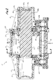
- Fig. 1 is an end elevational view partially in section of a ratio pump constructed in accordance with the teachings of this invention.
- Fig. 2 is a sectional view taken generally along line 2-2 of Fig. 1.
- Fig. 3 is a sectional view taken generally along line 3-3 of Fig. 2, and more specifically, along line 3-3 of Fig. 4.
- Fig. 4 is a sectional view taken generally along line 4-4 of Fig. 3.
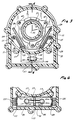
- Fig. 5 is a fragmentary, sectional view taken generally along line 5-5 of Fig. 4.
- Fig. 6 is a fragmentary, sectional view taken generally along line 6-6 of Fig. 5.
- the drawings show a ratio pump 11 which generally comprises a motor 13 (Fig. 2) and a pump 15.
- the ratio pump 11 includes a housing 17 which, in this embodiment, includes a central housing section 19 (Fig. 2) and identical end housing sections 21 and 21a, all of which are molded of a suitable plastic material.
- the housing sections 19, 21, and 21a are suitably interconnected as by threaded fasteners 23 (Fig. 1) and sealed together in any suitable manner as by a seal 25.
- the housing 17 has a water inlet 27, a water outlet or exhaust 29, a syrup inlet 31 and a syrup outlet 33.
- the inlets 27 and 31 and the outlets 29 and 33 can be connected to various different liquids.
- the ratio pump 11 is described with reference to ratioing of the beverage components of a beverage which comprises a soft drink syrup and a pressurized source of carbonated water.
- the water can be provided through a valve 35 which automatically shuts off when the supply of syrup is exhausted.
- the valve 35 may be a vacuum-operated valve which is coupled to the syrup inlet 31 so that it can sense the vacuum pressure that exists when the supply of syrup is used up.
- the motor 13 includes a motor chamber or cylinder 37 (Fig. 2) and a reciprocable member in the form of a double-acting piston 39 having opposed working faces 41 and 43.
- the piston 39 includes a flange 45 integral with a plunger 47 of plastic material, a main body or disc 49 and a seal 51 molded directly onto the periphery of the disc 49 in a process which does not require a separate bonding agent.
- the disc 49 may be threaded onto the flange 45, and the piston 39 and the plunger 47 are coaxial.
- the body 49 and the plunger 47 are constructed of plastic or other suitable material.
- the piston 39 is reciprocated in the cylinder 37 by the pressurized carbonated water from the water inlet 27 with each stroke of the piston requiring a predetermined volume of the pressurized water.
- a preferred manner of reciprocating the piston 39 is described hereinbelow.
- the pump 15 includes identical pumping chambers 53 and 53a and a reciprocable member in the form of plungers or plunger sections 55 and 55a which are reciprocable in the pumping chambers 53 and 53a, respectively.
- a seal gland 57 which includes a relatively rigid ring 59 and a seal 61 molded directly onto the inner periphery of the ring 59 in a manner that does not require the use of a separate bonding agent is removably attached in any suitable manner, such as by screws 60 (Fig. 3), to the housing section 21 to form an inner end of the pumping chamber 53.
- An identical removable seal gland 57a is provided for the pumping chamber 53a.
- syrup is admitted to the pumping chamber 53 on the intake stroke, i.e., when the plunger 55 moves to the right as viewed in Fig. 2, through an inlet check valve 63 (Fig. 1), which may be of conventional construction.
- syrup is discharged from the pumping chamber 53 on the discharge stroke, i.e., when the plunger 55 moves to the left as viewed in Fig. 2, through an outlet check valve 65.
- the pumping chamber 53a has an inlet check valve (not shown) identical to the inlet check valve 63 and an outlet check valve 65a.
- the discharge from both of the outlet check valves 65 and 65a is supplied to a header 67 which discharges to the syrup outlet 33 as shown in Fig. 2.
- the plungers 55 and 55a which, in the illustrated embodiment, form portions of the plunger 47, have identical working faces 69 and 69a, and it is apparent that the volume of syrup pumped by each of the pumping chambers 53 and 53a is directly proportional to the areas of the associated working face.
- the area of each of the working faces 41 and 43 of the piston 39 is 5.5 times as great as the area of each of the working faces 69 and 69a. Consequently, on each stroke of the piston 39, the ratio of water exhausted to syrup pumped will be 5.5 to 1 as explained more fully hereinbelow.
- the working faces 69 and 69a are part-spherical to match part-spherical end walls 71 and 71a of the pumping chambers 53 and 53a, respectively.
- the plunger 47 is integrally molded such that the plungers 55 and 55a are integral with each other and with the flange 45.
- valve means 73 (Fig. 5) either to a chamber 75 or a chamber 77 (Figs. 4 and 5) which communicate with the working faces 43 and 41, respectively, through identical passages 79 and 79a formed in the end housing sections 21 and 21a as shown in Fig. 4.
- the valve means 73 is in turn controlled by controlling means 81 (Figs. 4 and 5) which is operated by the piston 39.
- valve means 73 includes a linearly movable inlet valve element 83, a linearly movable exhaust valve element 85, dual valve seats 87 and 89 and dual valve seats 91 and 93 for the inlet and exhaust valve elements, respectively, and a connector 95 in the form of a rod for joining the valve elements for movement together.
- the valve elements 83 and 85 are mounted for movement in valve bodies 97 and 99, respectively, which are suitably retained within supporting structure 101 of the central housing section 19.
- valve means 73 With the valve means 73 in the position shown in Fig. 5, water at supply pressure can flow from the water inlet 27 past the valve seat 87 and through the chamber 75 and the passage 79a (Fig. 5) to the working face 43 to urge the piston 39 to the right as viewed in Fig. 4.
- the working face 41 communicates with the water outlet 29 through the passage 79, the chamber 77, the opening of the valve means at the valve seat 93 to the water outlet 29.
- the valve means 73 Conversely, with the valve means 73 moved to the left from the position shown in Fig. 5, the piston 39 is driven in the other direction.
- the controlling means 81 includes bistable spring means 103 in the housing for operating the valve means 73 and driving means which, in this embodiment, includes a shaft 105, a collar 107 for driving the bistable spring means over center in both directions, and pivotally mounted levers 109, 109a, 111 and 111a (Figs. 3 and 4) at opposite ends of the motor cylinder 37 which are pivotable by the piston 39 as it nears the ends of its strokes.
- the bistable spring means 103 can take different forms, in this embodiment, it includes a hinge member 113 (Figs.
- the bistable spring means 103 is a two-stage device which can be moved from the state shown in Fig. 5 over center to a position shown by phantom lines 127 by pushing the hinge member 113 to the left as viewed in Fig. 5. Conversely, the bistable spring means 103 can be returned to the full-line position of Fig. 5 by pushing the hinge member 113 to the right with the shaft 105.
- the levers 109 and 111 cooperate to move the collar 107 when the piston nears the end of the cylinder 37 occupied by these levers. More specifically, each of the levers 109 and 111 is mounted by a resilient pin or wireform mounting member 129 attached to the associated end housing section 21 and 21a by a suitable fastener 131, with a resilient leg 133 of the pin being received in an associated opening located intermediate the ends of the associated lever.
- the levers 109, 109a, 111 and 111a are substantially identical, except that the levers 111 and 109a may be considered as righthand and the levers 111a and 109 as lefthand. As shown in Fig.
- the lever 111 has a curved surface 135 adjacent to, but primarily on one side of, the leg 133.
- the curved surface 135 bears on a planar surface or abutment 137 formed on the housing section 21.
- One end of each of the levers 109-111a has a projection 139 (Fig. 4) engageable with the associated working faces 41 and 43.
- the projections 139 engage the piston 39 on the opposite sides of the central axis 141 of the piston.
- the opposite ends of the levers 109 and 111 are joined together by a pin 143 which extends through tabs 144 (Fig. 3), with the major lengths of these levers extending at an acute angle relative to the pin axis.
- the pin 143 for the levers 109 and 111 is covered with the collar 107, and the pin 143 for the levers 109a and 111a is covered by a collar 107a.
- the shaft 105 is mounted for sliding movement in the supporting structure 101.
- the shaft is biased to the left as viewed in Figs. 4 and 5 by a return spring 145 which acts against a retaining ring 147 carried by the shaft.
- the shaft 105 extends completely through the supporting structure 101, and its opposite ends are engageable with the collar 107a and the hinge member 113.
- the rolling pivotal movement of the levers 109 and 111 is accommodated by the resilience of the wireform mounting members 129 and, in particular, the legs 133.
- pivoting of the levers 109 and 111 in this fashion drives the collar 107 and the hinge member 113 to the left to move the bistable spring means 103 over center to the position shown in phantom lines 127.
- the connector 95 is engaged by the hinge member 113 after traveling the full length of the slot 116 to force the valve means 73 to its other position to bring about a reversal of the piston 39.
- the action at the opposite end of the cylinder 37 is similar when the working face 43 strikes the projection 139 of the levers 109a and 111a to pivot these levers in the same manner as described above.
- these levers drive the collar 107a and the shaft 105 against the biasing action of the spring 145 to cause the shaft to move the hinge member 113 through center in the opposite direction back to the position shown in Fig. 4.
- the connector 95 is moved by the hinge member 113 after the hinge member travels the full length of the slot 116 to switch the valve means 73 and reverse the piston 39.
- the water from the water outlet 29 and the syrup from the syrup outlet 33 can be brought together within the housing 17 or outside of the housing. As shown by way of example in Fig. 1, these outlets are brought together outside of the housing 17 into a common receiver which includes a water conduit 149 leading from the water outlet 29, a syrup conduit 151 leading from the syrup outlet 33 and a common discharge conduit 153 which receives the delivery from both of the conduits 149 and 151.
- the dispensing of the beverage from the discharge conduit 153 can be controlled by a dispensing valve 155.
- the syrup conduit 151 extends from the syrup outlet 33 all the way to the discharge conduit 153, and there is no shutoff valve in the conduit 151 or in the pump housing 17 upstream of the conduit 151.
- the conduit 151 and the entire conduit from there back to the outlet check valve 65 is incapable of shutting off flow of the syrup. If a valve were provided, for example, in the syrup discharge conduit 151, and if that valve were closed while the motor 13 were operating, the much higher discharge pressure of the syrup could overpressurize the pump and the delivery syrup conduits and bring about a failure.
- valve 155 With the valve 155 closed, the water exhaust from the motor 13 and the syrup delivery from the pump 15 are coupled into the closed conduit 153. Consequently, no differential pressure can be developed across the piston 39 and, no pumping takes place.
- the conduit 153 opens to allow water under pressure from the water inlet 27 to drive the piston 39 while the water in the cylinder 37 from the previous stroke of the piston 39 is open to exhaust across the valve seat 93 to the conduits 149 and 153. Accordingly, the piston 39 moves to the left as shown in Fig. 2 and to the right as shown in Fig. 4 to exhaust the water in the cylinder 37.
- syrup previously drawn into the pumping chamber 53 is pumped through the outlet check valve 65 and the header 67 to the conduits 151 and 153. Simultaneously, movement of the plunger 55a to the left on its intake stroke draws syrup from the syrup inlet 31 into the pumping chamber 53a through the associated inlet check valve (not shown).
- the volumes of water and syrup delivered are in a ratio established by the area of the working face 41 to the area of the working face 69.
- the motor 13 continues to operate for so long as the dispensing valve 155 is open. Demand operation is achieved without electrical wiring or a pressure switch. For example, the volume dispensed in a single stroke may be sufficient for a single drink.
Landscapes
- Engineering & Computer Science (AREA)
- Mechanical Engineering (AREA)
- General Engineering & Computer Science (AREA)
- Physics & Mathematics (AREA)
- Fluid Mechanics (AREA)
- General Physics & Mathematics (AREA)
- Reciprocating Pumps (AREA)
- Hydraulic Motors (AREA)
- Fluid-Pressure Circuits (AREA)
- Devices For Dispensing Beverages (AREA)
Description
- This invention relates to a reciprocating device in which a reciprocable member is mounted in a chamber for reciprocating movement by a driving fluid under pressure.
- EP-A1-0,109,746 discloses a reciprocating device comprising: a housing having a chamber therein; a reciprocable member mounted in the chamber for reciprocating movement therein and having first and second working faces; an inlet for admitting driving fluid under pressure to the chamber; an exhaust for exhausting the driving fluid from the chamber; valve means for controlling the admission and exhaust of the driving fluid into and out of the chamber, respectively; and controlling means for controlling the valve means so that the driving fluid can reciprocate the reciprocable member in the chamber; the controlling means including bistable spring means for operating the valve means and driving means for driving the bistable spring means over center in both directions, the driving means including first and second levers and means for pivotally mounting the said first and second levers, the levers of the driving means being pivotable by the reciprocable member as it nears the respective ends of its strokes to cause driving of the bistable spring means over dead center to operate the valve means.
- Such a reciprocating device is, according to the invention, characterised in that the levers are mounted at opposite ends of the chamber and the driving means includes an elongate shaft between the first lever and the bistable spring means and movable by the first lever to drive the bistable spring means over center in one direction.
- FR-A-1,601,032 discloses a reciprocating device in which the reciprocable member engages plungers extending through high pressure sliding seals to operate external levers for operating the valves. The device lacks any bistable spring means.
- The reciprocating device may be a ratio pump for providing first and second liquid components in a desired ratio wherein the first liquid component is pressurized, the said chamber is a motor chamber and the said driving fluid is the first liquid component with a predetermined volume of the first liquid component driving the reciprocable member through at least one of its strokes, a pump including means defining a pumping chamber, a reciprocable pumping member reciprocable in the pumping chamber, an inlet for admitting the second liquid component into the pumping chamber, an outlet for discharging the second liquid component from the pumping chamber with each delivery stroke of the pumping member pumping a predetermined volume of the second liquid components, means for drivingly coupling the reciprocable members whereby the reciprocable member reciprocates the reciprocable pumping member, and a receiver coupled to the exhaust to receive the first liquid component and the outlet of the pump to receiving the second liquid component delivered from the pump whereby the receiver receives the first and second liquid components in the desired ratio.
- Such a ratio pump may be used in a beverage dispenser. Many beverages comprise multiple liquid components, such as water and a syrup or a concentrate. The water may or may not be carbonated, and the syrup may be, for example, a soft drink syrup, and the concentrate may be, for example, a fruit juice or tea concentrate. The beverage components are typically mixed as the beverage is dispensed at the serving facility. In order to have a beverage with the desired taste, it is very important that the beverage components be mixed in the correct ratio.
- In a conventional system, the water and syrup or concentrate are provided through separate proportioning valves to a dispensing outlet. The valves must be initially carefully set to establish the desired ratio and then should be re-adjusted daily to maintain the correct ratio. The syrup or concentrate is pumped to its proportioning valve by a pump driven by carbon dioxide gas.
- This conventional system has experienced numerous problems. For example, the valve-adjusting process is time-consuming, and the valve re-adjusting process may not be carried out frequently enough to maintain the desired ratio. Furthermore, even if the valves are correctly adjusted, pressure changes in either of the beverage components furnished to the valves results in the dispensing of a beverage having the incorrect ratio of components. Also, fibrous concentrates, such as juice concentrates containing pulp, tend to foul the concentrate proportioning valve. Finally, the pumping of the syrup or concentrate with carbon dioxide gas is wasteful in that the gas is exhausted to the atmosphere after it is used by the pump.
- The ratio pump incorporating the invention solves the problems described above with the conventional system. Thus, this pump eliminates the proportioning valves of the prior art, along with the attendant problems of valve adjustment and valve fouling by the concentrate. This pump provides the desired ratio of beverage components even if line pressure should vary and does not require or waste carbon dioxide gas for the pumping of the concentrate or syrup. Although this pump is applicable to the delivery of multiple liquid components generally, it is particularly adapted for use with beverage components and is described with respect thereto.
- In a typical beverage, the water component is usually supplied at a positive pressure. This pump uses the pressurized component, which is typically the water component, as the source of power for a motor which drives a pump that pumps the other beverage component. After being used as the driving fluid, the pressurized component is then exhausted for ultimate delivery along with the pumped component for use in the beverage. Accordingly, one of the beverage components is used as the source of power for pumping the other of the components.
- To ensure that the desired ratio is maintained, it is important to employ a motor which utilizes a fixed volume of water in causing the pump to pump a fixed volume of the pumped component. By so doing, the volume of water exhausted from the motor will always bear a predetermined relationship to the volume of the pumped component delivered by the pump.
- Although different constructions are possible, the motor can advantageously include a motor chamber and a reciprocable member which can be driven through strokes of a predetermined length in the motor chamber. Similarly, the pump can advantageously include a pumping chamber and a reciprocable pumping member which can be driven through strokes of predetermined length in the pumping chamber. Accordingly, the ratio of motor exhaust to pump delivery will equal the ratio of the areas of the working faces of the reciprocable members of the motor and pump, respectively. A fixed ratio of the beverage components is delivered even if supply pressures of the beverage components to the motor and/or pump should change.
- With this construction, the beverage component ratio is fixed. However, the ratio can be changed to a new fixed ratio. This can be accomplished, for example, by providing a removable seal gland for sealingly cooperating with the reciprocable pumping member. The seal gland and the pumping member can then be replaced to provide a pumping member having a larger or smaller area to thereby change the ratio.
- The reciprocable members can be of a variety of constructions and may be, for example, a diaphragm or piston. However, a piston or other rigid member is preferred because it provides greater volumetric accuracy.
- The motor exhaust and the delivery of the pump are fed into a receiver, either within the pump itself or downstream thereof, so that the beverage components can mix. For example, the receiver may include first and second conduits leading, respectively, from the motor exhaust and the pump outlet and a common discharge conduit joined to the first and second conduits. With this invention, the conduit leading from the pump outlet is devoid of any shutoff valve so that it is incapable of shutting off flow of the pumped component. This is important as a safety measure to assure that this region of the conduit and pump cannot be overpressurized. This is particularly important because a typical ratio of the pressurized water to concentrate is 5.5 to 1, and accordingly, the concentrate is delivered at, in this example, 5.5 times the pressure of the water. It is, therefore, desirable to assure that overpressurizing of the pump and its discharge line is not likely to occur.
- In a preferred construction, the ratio pump of this invention includes a housing, and the reciprocable members of the pump and motor are coaxially coupled within the housing. To obtain pump delivery on each stroke of the pump, the pump preferably has first and second pumping chambers which are preferably located at the opposite ends of the motor chamber and first and second plungers coupled to the motor piston for reciprocating within the first and second pumping chambers, respectively.
- In order that the reciprocable member of the motor can reciprocate, it is necessary to switch the opposite working faces of the reciprocable member between an inlet for admitting driving fluid under pressure and an exhaust for exhausting the driving fluid under pressure from the chamber. This is accomplished by valve means which control the admission and exhaust of the liquid component into, and from, the motor chamber, respectively, and means for controlling the valve means so that the liquid component can reciprocate the reciprocable member. This invention also provides novel controlling means which can be used with the ratio pump of this invention, or with various reciprocating devices, such as motors and compressors, where a switching action of valves is required.
- For example, the controlling means can advantageously include bistable spring means for operating the valve means and driving means for driving the bistable spring means over center in both directions. The driving means may include first and second pivotally mounted levers at opposite ends of the motor chamber which are pivotable by the reciprocable member as it nears the ends of its strokes to control the valve means.
- The invention, together with additional features and advantages thereof, may best be understood by reference to the following description taken in connection with the accompanying illustrative drawing.
- Fig. 1 is an end elevational view partially in section of a ratio pump constructed in accordance with the teachings of this invention.
- Fig. 2 is a sectional view taken generally along line 2-2 of Fig. 1.
- Fig. 3 is a sectional view taken generally along line 3-3 of Fig. 2, and more specifically, along line 3-3 of Fig. 4.
- Fig. 4 is a sectional view taken generally along line 4-4 of Fig. 3.
- Fig. 5 is a fragmentary, sectional view taken generally along line 5-5 of Fig. 4.
- Fig. 6 is a fragmentary, sectional view taken generally along line 6-6 of Fig. 5.
- The drawings show a ratio pump 11 which generally comprises a motor 13 (Fig. 2) and a
pump 15. The ratio pump 11 includes ahousing 17 which, in this embodiment, includes a central housing section 19 (Fig. 2) and identicalend housing sections 21 and 21a, all of which are molded of a suitable plastic material. Thehousing sections seal 25. - As shown in Fig. 1, the
housing 17 has awater inlet 27, a water outlet orexhaust 29, asyrup inlet 31 and asyrup outlet 33. Of course, theinlets outlets valve 35 which automatically shuts off when the supply of syrup is exhausted. For example, thevalve 35 may be a vacuum-operated valve which is coupled to thesyrup inlet 31 so that it can sense the vacuum pressure that exists when the supply of syrup is used up. - The
motor 13 includes a motor chamber or cylinder 37 (Fig. 2) and a reciprocable member in the form of a double-actingpiston 39 having opposed working faces 41 and 43. Thepiston 39 includes aflange 45 integral with aplunger 47 of plastic material, a main body ordisc 49 and aseal 51 molded directly onto the periphery of thedisc 49 in a process which does not require a separate bonding agent. Thedisc 49 may be threaded onto theflange 45, and thepiston 39 and theplunger 47 are coaxial. Thebody 49 and theplunger 47 are constructed of plastic or other suitable material. - In operation, the
piston 39 is reciprocated in thecylinder 37 by the pressurized carbonated water from thewater inlet 27 with each stroke of the piston requiring a predetermined volume of the pressurized water. A preferred manner of reciprocating thepiston 39 is described hereinbelow. - The
pump 15 includesidentical pumping chambers plunger sections pumping chambers seal gland 57 which includes a relativelyrigid ring 59 and aseal 61 molded directly onto the inner periphery of thering 59 in a manner that does not require the use of a separate bonding agent is removably attached in any suitable manner, such as by screws 60 (Fig. 3), to thehousing section 21 to form an inner end of the pumpingchamber 53. An identical removable seal gland 57a is provided for thepumping chamber 53a. - As shown in Fig. 2, syrup is admitted to the
pumping chamber 53 on the intake stroke, i.e., when theplunger 55 moves to the right as viewed in Fig. 2, through an inlet check valve 63 (Fig. 1), which may be of conventional construction. Similarly, syrup is discharged from the pumpingchamber 53 on the discharge stroke, i.e., when theplunger 55 moves to the left as viewed in Fig. 2, through anoutlet check valve 65. Thepumping chamber 53a has an inlet check valve (not shown) identical to theinlet check valve 63 and anoutlet check valve 65a. As shown in Fig. 2, the discharge from both of theoutlet check valves header 67 which discharges to thesyrup outlet 33 as shown in Fig. 2. - The
plungers plunger 47, have identical working faces 69 and 69a, and it is apparent that the volume of syrup pumped by each of thepumping chambers piston 39 is 5.5 times as great as the area of each of the working faces 69 and 69a. Consequently, on each stroke of thepiston 39, the ratio of water exhausted to syrup pumped will be 5.5 to 1 as explained more fully hereinbelow. - Although various different constructions are possible, in this embodiment, the working faces 69 and 69a are part-spherical to match part-spherical end walls 71 and 71a of the
pumping chambers plunger 47 is integrally molded such that theplungers flange 45. - Considering next a preferred manner of using the water under pressure to reciprocate the
piston 39, the water under pressure from the water inlet 27 (Figs. 1 and 5) is directed by valve means 73 (Fig. 5) either to achamber 75 or a chamber 77 (Figs. 4 and 5) which communicate with the working faces 43 and 41, respectively, throughidentical passages 79 and 79a formed in theend housing sections 21 and 21a as shown in Fig. 4. The valve means 73 is in turn controlled by controlling means 81 (Figs. 4 and 5) which is operated by thepiston 39. - More specifically, the valve means 73 includes a linearly movable
inlet valve element 83, a linearly movableexhaust valve element 85, dual valve seats 87 and 89 and dual valve seats 91 and 93 for the inlet and exhaust valve elements, respectively, and aconnector 95 in the form of a rod for joining the valve elements for movement together. Thevalve elements valve bodies structure 101 of thecentral housing section 19. - With the valve means 73 in the position shown in Fig. 5, water at supply pressure can flow from the
water inlet 27 past thevalve seat 87 and through thechamber 75 and the passage 79a (Fig. 5) to the workingface 43 to urge thepiston 39 to the right as viewed in Fig. 4. In addition, the workingface 41 communicates with thewater outlet 29 through thepassage 79, thechamber 77, the opening of the valve means at the valve seat 93 to thewater outlet 29. Conversely, with the valve means 73 moved to the left from the position shown in Fig. 5, thepiston 39 is driven in the other direction. - Generally, the controlling means 81 includes bistable spring means 103 in the housing for operating the valve means 73 and driving means which, in this embodiment, includes a
shaft 105, acollar 107 for driving the bistable spring means over center in both directions, and pivotally mountedlevers motor cylinder 37 which are pivotable by thepiston 39 as it nears the ends of its strokes. Although the bistable spring means 103 can take different forms, in this embodiment, it includes a hinge member 113 (Figs. 4 and 5) havingrecesses 115 in its opposite faces and anelongated slot 116 to slidably accommodate theconnector 95 with some lost motion, longitudinallyrigid arms 117 having their inner ends received within therecesses 115, respectively, a resilient, channel-shapedbracket 119 suitably joined to the supportingstructure 101 as byscrews 121 and having outwardly projectingresilient legs 123 with apertures for receiving the outer ends of thearms 117, respectively, and springs 125 urging thelegs 123 inwardly and thearms 117 into therecesses 115. As best seen in Fig. 6, thearms 117 are bifurcated to provide clearance for thevalve elements connector 95. The bistable spring means 103 is a two-stage device which can be moved from the state shown in Fig. 5 over center to a position shown byphantom lines 127 by pushing thehinge member 113 to the left as viewed in Fig. 5. Conversely, the bistable spring means 103 can be returned to the full-line position of Fig. 5 by pushing thehinge member 113 to the right with theshaft 105. - The
levers 109 and 111 (Figs. 3-5) cooperate to move thecollar 107 when the piston nears the end of thecylinder 37 occupied by these levers. More specifically, each of thelevers 109 and 111 is mounted by a resilient pin orwireform mounting member 129 attached to the associatedend housing section 21 and 21a by asuitable fastener 131, with aresilient leg 133 of the pin being received in an associated opening located intermediate the ends of the associated lever. Thelevers levers 111 and 109a may be considered as righthand and thelevers 111a and 109 as lefthand. As shown in Fig. 4, the lever 111 has acurved surface 135 adjacent to, but primarily on one side of, theleg 133. Thecurved surface 135 bears on a planar surface orabutment 137 formed on thehousing section 21. One end of each of the levers 109-111a has a projection 139 (Fig. 4) engageable with the associated working faces 41 and 43. As shown in Fig. 3, theprojections 139 engage thepiston 39 on the opposite sides of thecentral axis 141 of the piston. The opposite ends of thelevers 109 and 111 are joined together by apin 143 which extends through tabs 144 (Fig. 3), with the major lengths of these levers extending at an acute angle relative to the pin axis. Thepin 143 for thelevers 109 and 111 is covered with thecollar 107, and thepin 143 for thelevers 109a and 111a is covered by acollar 107a. - The
shaft 105 is mounted for sliding movement in the supportingstructure 101. The shaft is biased to the left as viewed in Figs. 4 and 5 by areturn spring 145 which acts against a retainingring 147 carried by the shaft. Theshaft 105 extends completely through the supportingstructure 101, and its opposite ends are engageable with thecollar 107a and thehinge member 113. Thus, when thepiston 39 travels to the extreme right as shown in Fig. 4, it will contact theprojections 139 of thelevers 109 and 111 and pivot them by causing thecurved surfaces 135 to roll on theabutments 137 to pivot the levers clockwise as shown in Fig. 4. The rolling pivotal movement of thelevers 109 and 111 is accommodated by the resilience of thewireform mounting members 129 and, in particular, thelegs 133. Of course, pivoting of thelevers 109 and 111 in this fashion drives thecollar 107 and thehinge member 113 to the left to move the bistable spring means 103 over center to the position shown in phantom lines 127. Specifically, theconnector 95 is engaged by thehinge member 113 after traveling the full length of theslot 116 to force the valve means 73 to its other position to bring about a reversal of thepiston 39. The action at the opposite end of thecylinder 37 is similar when the workingface 43 strikes theprojection 139 of thelevers 109a and 111a to pivot these levers in the same manner as described above. In this instance, these levers drive thecollar 107a and theshaft 105 against the biasing action of thespring 145 to cause the shaft to move thehinge member 113 through center in the opposite direction back to the position shown in Fig. 4. Again, theconnector 95 is moved by thehinge member 113 after the hinge member travels the full length of theslot 116 to switch the valve means 73 and reverse thepiston 39. - The water from the
water outlet 29 and the syrup from thesyrup outlet 33 can be brought together within thehousing 17 or outside of the housing. As shown by way of example in Fig. 1, these outlets are brought together outside of thehousing 17 into a common receiver which includes awater conduit 149 leading from thewater outlet 29, asyrup conduit 151 leading from thesyrup outlet 33 and acommon discharge conduit 153 which receives the delivery from both of theconduits discharge conduit 153 can be controlled by a dispensingvalve 155. Thesyrup conduit 151 extends from thesyrup outlet 33 all the way to thedischarge conduit 153, and there is no shutoff valve in theconduit 151 or in thepump housing 17 upstream of theconduit 151. Accordingly, theconduit 151 and the entire conduit from there back to theoutlet check valve 65 is incapable of shutting off flow of the syrup. If a valve were provided, for example, in thesyrup discharge conduit 151, and if that valve were closed while themotor 13 were operating, the much higher discharge pressure of the syrup could overpressurize the pump and the delivery syrup conduits and bring about a failure. - The operation of the ratio pump 11 should now be apparent. With the
valve 155 closed, the water exhaust from themotor 13 and the syrup delivery from thepump 15 are coupled into theclosed conduit 153. Consequently, no differential pressure can be developed across thepiston 39 and, no pumping takes place. However, when a beverage is demanded by opening of the valve 155 (Fig. 1), theconduit 153 opens to allow water under pressure from thewater inlet 27 to drive thepiston 39 while the water in thecylinder 37 from the previous stroke of thepiston 39 is open to exhaust across the valve seat 93 to theconduits piston 39 moves to the left as shown in Fig. 2 and to the right as shown in Fig. 4 to exhaust the water in thecylinder 37. In addition, syrup previously drawn into the pumpingchamber 53 is pumped through theoutlet check valve 65 and theheader 67 to theconduits plunger 55a to the left on its intake stroke draws syrup from thesyrup inlet 31 into thepumping chamber 53a through the associated inlet check valve (not shown). - The volumes of water and syrup delivered are in a ratio established by the area of the working
face 41 to the area of the workingface 69. When thepiston 39 nears the end of its stroke, itsface 41 engages theprojections 139 of thelevers 109 and 111 to pivot them as described above to move the bistable spring means 103 over center and switch the position of the valve means 73. This causes thepiston 39 to reverse and to repeat the action described above, except that the piston andplunger 47 travel in the opposite direction. - The
motor 13 continues to operate for so long as the dispensingvalve 155 is open. Demand operation is achieved without electrical wiring or a pressure switch. For example, the volume dispensed in a single stroke may be sufficient for a single drink.
Claims (8)
- A reciprocating device comprising: a housing (17) having a chamber (37) therein; a reciprocable member (39) mounted in the chamber for reciprocating movement therein and having first and second working faces; an inlet (27) for admitting driving fluid under pressure to the chamber; an exhaust (29) for exhausting the driving fluid from the chamber; valve means (73) for controlling the admission and exhaust of the driving fluid into and out of the chamber, respectively; and controlling means (81) for controlling the valve means so that the driving fluid can reciprocate the reciprocable member in the chamber; the controlling means (81) including bistable spring means (103) for operating the valve means (73) and driving means (105, 107, 109, 109a, 111, 111a) for driving the bistable spring means (103) over center in both directions, the driving means including first and second levers (111, 111a) and means (129, 133, 135, 137) for pivotally mounting the said first and second levers at opposite ends of the chamber (37), the levers of the driving means being pivotable by the reciprocable member (39) as it nears the respective ends of its strokes to cause driving of the bistable spring means over dead center to operate the valve means; characterised in that the levers (111, 111a) are mounted at opposite ends of the chamber (37) and the driving means includes an elongate shaft (105 between the first lever (111) and the bistable spring means (103) and movable by the first lever to drive the bistable spring means over center in one direction.
- A reciprocating device as defined in claim 1 characterised in that pivotal mounting means includes an abutment (137) and a cooperating surface (135) on the first lever (111) engageable with the abutment (137) and adapted to roll on the abutment to pivot said first lever (111)
- A reciprocating device as defined in claim 2 characterised in that the pivotal mounting means includes a pin (129) coupled to the first lever (111) which is sufficiently resilient to accommodate the rolling movement of the first lever (111) on the abutment.
- A reciprocating device as defined in claims 1, 2 or 3 characterised in that the driving means includes a third pivotally mounted lever (109) at the same end of the chamber (37) as the first lever (111), the first and third levers engaging the reciprcable member (39) on opposite sides of its axis n ear the end of one of the strokes of the reciprocable member.
- A reciprocating device as defined in claim 1 characterised in that the reciprocating device is a ratio pump for providing first and second liquid components in a desired ratio wherein the first liquid component is pressurized, the said chamber is a motor chamber and the said driving fluid is the first liquid component with a predetermined volume of the first liquid component driving the reciprocable member (39) through at least one of its strokes, a pump (11) including means defining a pumping chamber (53, 53a), a reciprocable pumping member (55, 55a) reciprocable in the pumping chamber, an inlet (31) for admitting the second liquid component into the pumping chamber, an outlet (33) for discharging the second liquid component from the pumping chamber with each delivery stroke of the pumping member (55, 55a) pumping a predetermined volume of the second liquid component, means for drivingly coupling the reciprocable members (39, 55, 55a) whereby the reciprocable member (39) reciprocates the reciprocable pumping member (55, 55a), and a receiver (149, 151, 153) coupled to the exhaust to receive the first liquid component and the outlet (33) of the pump (11) to receive the second liquid component delivered from the pump (11) whereby the receiver (149, 151, 153) receives the first and second liquid components in the desired ratio.
- A reciprocating device as defined in claim 5 characterised in that the coupling means includes means for coaxially coupling the reciprocable members.
- A reciprocating device as defined in claims 5 or 6 characterised in that the reciprocable member of the motor has a working face (41) on which the first liquid component acts and the reciprocable pumping member has a working face (69a) which acts against the second liquid component to pump the second liquid component, the working face (41) of the reciprocable member of the motor having a larger area than the working face (69a) of the reciprocable member of the pump, the receiver includes first and second conduits (149, 151) leading from the motor exhaust (29) and the pump outlet (33), respectively, and a common discharge conduit (153) joined to both of the first and second conduits, the second conduit (151) being incapable of shutting off flow of the second liquid component whereby the likelihood of a failure resulting from overpressurizing of the second conduit is reduced.
- A reciprocating device as defined in claims 5, 6 or 7 characterised in that the said pumping chamber includes first and second pumping chambers (53, 53a) in the said housing (17) and the reciprocable pumping member includes first and second reciprocable plungers (55, 55a) coupled to the reciprocable member (39) and reciprocated thereby in the pumping chambers (53, 53a), respectively, whereby each delivery stroke of the plungers (55, 55a) pumps a predetermined volume of the second liquid component.
Applications Claiming Priority (2)
| Application Number | Priority Date | Filing Date | Title |
|---|---|---|---|
| US797620 | 1985-11-13 | ||
| US06/797,620 US4684332A (en) | 1985-11-13 | 1985-11-13 | Ratio pump and method |
Publications (3)
| Publication Number | Publication Date |
|---|---|
| EP0223568A2 EP0223568A2 (en) | 1987-05-27 |
| EP0223568A3 EP0223568A3 (en) | 1988-09-14 |
| EP0223568B1 true EP0223568B1 (en) | 1992-08-12 |
Family
ID=25171347
Family Applications (1)
| Application Number | Title | Priority Date | Filing Date |
|---|---|---|---|
| EP86308871A Expired EP0223568B1 (en) | 1985-11-13 | 1986-11-13 | Ratio pump |
Country Status (4)
| Country | Link |
|---|---|
| US (1) | US4684332A (en) |
| EP (1) | EP0223568B1 (en) |
| JP (1) | JPH0819899B2 (en) |
| DE (1) | DE3686392T2 (en) |
Families Citing this family (27)
| Publication number | Priority date | Publication date | Assignee | Title |
|---|---|---|---|---|
| US5071038A (en) * | 1986-07-18 | 1991-12-10 | The Coca-Cola Company | Beverage dispenser system using volumetric ratio control device |
| CA1317913C (en) * | 1986-07-18 | 1993-05-18 | William S. Credle, Jr. | Beverage dispenser system using volumetric ratio control device |
| US5060824A (en) * | 1986-07-18 | 1991-10-29 | The Coca-Cola Company | Beverage dispenser system using volumetric ratio control device |
| DE3855689T2 (en) * | 1987-05-28 | 1997-03-20 | Yamada Yuki Seizo Co Ltd | Floating circuit structure for pumps |
| US4830583A (en) * | 1988-03-02 | 1989-05-16 | Sri International | Fluid motor-pumping apparatus and system |
| AU5420090A (en) * | 1989-03-31 | 1990-11-05 | Fountain Fresh, Inc. | Methods and apparatus for dispensing plural fluids in a precise proportion |
| US5000352A (en) * | 1989-08-31 | 1991-03-19 | Cleland Robert K | Beverage dispensing apparatus |
| US5156301A (en) * | 1990-12-17 | 1992-10-20 | Imi Cornelius Inc. | Constant ratio post-mix beverage dispensing valve |
| DK168947B1 (en) * | 1992-05-07 | 1994-07-18 | Berke Joergensen Joergen | The metering devices |
| US5324175A (en) * | 1993-05-03 | 1994-06-28 | Northern Research & Engineering Corporation | Pneumatically operated reciprocating piston compressor |
| US5500113A (en) * | 1993-10-13 | 1996-03-19 | Shurflo Pump Manufacturing Co. | Reverse osmosis water system |
| US5470209A (en) * | 1993-10-13 | 1995-11-28 | Shurflo Pump Manufacturing Co. | Offset reciprocable device |
| US5505593A (en) * | 1993-10-13 | 1996-04-09 | Shurflo Pump Manufacturing Co. | Reciprocable device with switching mechanism |
| US5388725A (en) * | 1993-11-24 | 1995-02-14 | Fountain Fresh International | Fluid-driven apparatus for dispensing plural fluids in a precise proportion |
| US5499745A (en) * | 1994-02-18 | 1996-03-19 | Nordson Corporation | Apparatus for mixing and dispensing two chemically reactive materials |
| US5433349A (en) * | 1994-05-06 | 1995-07-18 | The Coca-Cola Company | Mixing and flushing device for juice dispensing tower |
| CN1138141A (en) * | 1995-02-08 | 1996-12-18 | 格雷科有限公司 | Diaphragm pump plural component dispensing system |
| USD380479S (en) * | 1996-03-06 | 1997-07-01 | Teledyne Industries, Inc. | Modular pump |
| US5626467A (en) * | 1996-04-04 | 1997-05-06 | Teledyne Industries, Inc. | Modular pump |
| US6349852B1 (en) | 1999-05-04 | 2002-02-26 | Bunn-O-Matic Corporation | Cold beverage refill system |
| US8303277B2 (en) * | 2002-11-21 | 2012-11-06 | International Dispensing Corporation | Blending pump assembly |
| US20050072800A1 (en) * | 2003-09-19 | 2005-04-07 | Smith Clyde M. | Fluid powered proportioning pump and post-mix beverage dispenser system using same |
| US20050123416A1 (en) * | 2003-12-06 | 2005-06-09 | Smith Clyde M. | Combined piston fluid motor and pump |
| US8046976B2 (en) | 2006-07-25 | 2011-11-01 | The Coca-Cola Company | Devices and methods for packaging beverages |
| GB2478867A (en) * | 2008-09-15 | 2011-09-21 | Everpure Llc | Mixed beverage dispense system and method |
| CN105889154A (en) * | 2014-11-28 | 2016-08-24 | 陕西鼎基能源科技有限公司 | High-pressure gas pressure energy isentropic supercharger |
| US10899597B2 (en) | 2018-02-16 | 2021-01-26 | Cleland Sales Corporation | Fluid control shutoff and pump assembly for a beverage dispensing machine |
Family Cites Families (9)
| Publication number | Priority date | Publication date | Assignee | Title |
|---|---|---|---|---|
| US1920014A (en) * | 1931-06-26 | 1933-07-25 | Trico Products Corp | Multiple diaphragm pump |
| US2945444A (en) * | 1957-09-23 | 1960-07-19 | Dynex Inc | Hydraulic pump |
| US3070023A (en) * | 1959-09-28 | 1962-12-25 | Nat Tank Co | Fluid operated pump |
| AT284632B (en) * | 1968-01-02 | 1970-09-25 | Hammelmann Paul Maschf | Device for generating press water of different pressure |
| DE1811953A1 (en) * | 1968-11-30 | 1970-06-11 | Wilhelm Krosse | Differential pressure metering pump |
| US4119113A (en) * | 1975-02-06 | 1978-10-10 | Extracorporeal Medical Systems, Inc. | Double-action proportioning pump |
| US4354806A (en) * | 1980-01-29 | 1982-10-19 | The Coca-Cola Company | Pneumatically powerable double acting positive displacement fluid pump |
| DE3100708A1 (en) * | 1980-01-31 | 1981-12-17 | Arcana Chem.-pharm. Fabrik GmbH, 9802 Spittal, Drau | DOSING DEVICE |
| US4827832A (en) * | 1982-11-22 | 1989-05-09 | Product Research And Development | Valve system for a reciprocating device |
-
1985
- 1985-11-13 US US06/797,620 patent/US4684332A/en not_active Expired - Lifetime
-
1986
- 1986-11-12 JP JP61267903A patent/JPH0819899B2/en not_active Expired - Lifetime
- 1986-11-13 EP EP86308871A patent/EP0223568B1/en not_active Expired
- 1986-11-13 DE DE8686308871T patent/DE3686392T2/en not_active Expired - Fee Related
Also Published As
| Publication number | Publication date |
|---|---|
| EP0223568A3 (en) | 1988-09-14 |
| JPS62113867A (en) | 1987-05-25 |
| US4684332A (en) | 1987-08-04 |
| DE3686392T2 (en) | 1993-01-28 |
| JPH0819899B2 (en) | 1996-03-04 |
| EP0223568A2 (en) | 1987-05-27 |
| DE3686392D1 (en) | 1992-09-17 |
Similar Documents
| Publication | Publication Date | Title |
|---|---|---|
| US4684332A (en) | Ratio pump and method | |
| US5170912A (en) | Proportioning pump | |
| US4540349A (en) | Air driven pump | |
| US4927567A (en) | Motorless continuous carbonator | |
| US6464107B1 (en) | Dosage dispenser | |
| US5664940A (en) | Gas driven pump | |
| EP2041396B1 (en) | Fluid-powered proportioning pump and system for dispensing fluid including such a pump | |
| US5033943A (en) | Low fluid shear pump | |
| US5058768A (en) | Methods and apparatus for dispensing plural fluids in a precise proportion | |
| KR940008167B1 (en) | Single acting gas operated pump | |
| US5388725A (en) | Fluid-driven apparatus for dispensing plural fluids in a precise proportion | |
| US5470209A (en) | Offset reciprocable device | |
| US5188255A (en) | Method and apparatus for facilitating the cleaning of a spray aperture in a mixing chamber of a nozzle | |
| US4634350A (en) | Double acting diaphragm pump and reversing mechanism therefor | |
| US4480969A (en) | Fluid operated double acting diaphragm pump housing and method | |
| GB2060086A (en) | Reciprocating Pump Apparatus and Reversing Mechanism Therefor | |
| US4827832A (en) | Valve system for a reciprocating device | |
| CN221180162U (en) | A pump-valve integrated structure and a water heater system composed of the same | |
| US4828465A (en) | Single-acting, gas-operated pump | |
| US4827831A (en) | Reciprocating device and switching mechanism therefor | |
| AU2004252526A1 (en) | Integrated pump and ceramic valve | |
| US20060159574A1 (en) | Piston pump | |
| JPH10281057A (en) | Transport device with metering pump | |
| EP0466772A4 (en) | Methods and apparatus for dispensing plural fluids in a precise proportion | |
| CN117204730A (en) | A pump-valve integrated structure and its constituted hot water purifier system |
Legal Events
| Date | Code | Title | Description |
|---|---|---|---|
| PUAI | Public reference made under article 153(3) epc to a published international application that has entered the european phase |
Free format text: ORIGINAL CODE: 0009012 |
|
| AK | Designated contracting states |
Kind code of ref document: A2 Designated state(s): DE ES FR GB IT NL SE |
|
| PUAL | Search report despatched |
Free format text: ORIGINAL CODE: 0009013 |
|
| AK | Designated contracting states |
Kind code of ref document: A3 Designated state(s): DE ES FR GB IT NL SE |
|
| 17P | Request for examination filed |
Effective date: 19890224 |
|
| 17Q | First examination report despatched |
Effective date: 19890803 |
|
| GRAA | (expected) grant |
Free format text: ORIGINAL CODE: 0009210 |
|
| AK | Designated contracting states |
Kind code of ref document: B1 Designated state(s): DE ES FR GB IT NL SE |
|
| PG25 | Lapsed in a contracting state [announced via postgrant information from national office to epo] |
Ref country code: IT Free format text: LAPSE BECAUSE OF FAILURE TO SUBMIT A TRANSLATION OF THE DESCRIPTION OR TO PAY THE FEE WITHIN THE PRESCRIBED TIME-LIMIT;WARNING: LAPSES OF ITALIAN PATENTS WITH EFFECTIVE DATE BEFORE 2007 MAY HAVE OCCURRED AT ANY TIME BEFORE 2007. THE CORRECT EFFECTIVE DATE MAY BE DIFFERENT FROM THE ONE RECORDED. Effective date: 19920812 Ref country code: SE Free format text: THE PATENT HAS BEEN ANNULLED BY A DECISION OF A NATIONAL AUTHORITY Effective date: 19920812 |
|
| REF | Corresponds to: |
Ref document number: 3686392 Country of ref document: DE Date of ref document: 19920917 |
|
| PG25 | Lapsed in a contracting state [announced via postgrant information from national office to epo] |
Ref country code: ES Free format text: LAPSE BECAUSE OF FAILURE TO SUBMIT A TRANSLATION OF THE DESCRIPTION OR TO PAY THE FEE WITHIN THE PRESCRIBED TIME-LIMIT Effective date: 19921123 |
|
| ET | Fr: translation filed | ||
| PLBE | No opposition filed within time limit |
Free format text: ORIGINAL CODE: 0009261 |
|
| STAA | Information on the status of an ep patent application or granted ep patent |
Free format text: STATUS: NO OPPOSITION FILED WITHIN TIME LIMIT |
|
| 26N | No opposition filed | ||
| PGFP | Annual fee paid to national office [announced via postgrant information from national office to epo] |
Ref country code: FR Payment date: 20001130 Year of fee payment: 15 |
|
| PGFP | Annual fee paid to national office [announced via postgrant information from national office to epo] |
Ref country code: NL Payment date: 20010331 Year of fee payment: 15 |
|
| REG | Reference to a national code |
Ref country code: GB Ref legal event code: IF02 |
|
| PG25 | Lapsed in a contracting state [announced via postgrant information from national office to epo] |
Ref country code: NL Free format text: LAPSE BECAUSE OF NON-PAYMENT OF DUE FEES Effective date: 20020601 |
|
| PG25 | Lapsed in a contracting state [announced via postgrant information from national office to epo] |
Ref country code: FR Free format text: LAPSE BECAUSE OF NON-PAYMENT OF DUE FEES Effective date: 20020730 |
|
| NLV4 | Nl: lapsed or anulled due to non-payment of the annual fee |
Effective date: 20020601 |
|
| REG | Reference to a national code |
Ref country code: FR Ref legal event code: ST |
|
| REG | Reference to a national code |
Ref country code: FR Ref legal event code: ST |
|
| PGFP | Annual fee paid to national office [announced via postgrant information from national office to epo] |
Ref country code: GB Payment date: 20041110 Year of fee payment: 19 |
|
| PGFP | Annual fee paid to national office [announced via postgrant information from national office to epo] |
Ref country code: DE Payment date: 20041230 Year of fee payment: 19 |
|
| PG25 | Lapsed in a contracting state [announced via postgrant information from national office to epo] |
Ref country code: GB Free format text: LAPSE BECAUSE OF NON-PAYMENT OF DUE FEES Effective date: 20051113 |
|
| PG25 | Lapsed in a contracting state [announced via postgrant information from national office to epo] |
Ref country code: DE Free format text: LAPSE BECAUSE OF NON-PAYMENT OF DUE FEES Effective date: 20060601 |
|
| GBPC | Gb: european patent ceased through non-payment of renewal fee |
Effective date: 20051113 |