EP2041396B1 - Fluid-powered proportioning pump and system for dispensing fluid including such a pump - Google Patents
Fluid-powered proportioning pump and system for dispensing fluid including such a pump Download PDFInfo
- Publication number
- EP2041396B1 EP2041396B1 EP07848937A EP07848937A EP2041396B1 EP 2041396 B1 EP2041396 B1 EP 2041396B1 EP 07848937 A EP07848937 A EP 07848937A EP 07848937 A EP07848937 A EP 07848937A EP 2041396 B1 EP2041396 B1 EP 2041396B1
- Authority
- EP
- European Patent Office
- Prior art keywords
- fluid
- pump
- chamber
- motor
- valve
- Prior art date
- Legal status (The legal status is an assumption and is not a legal conclusion. Google has not performed a legal analysis and makes no representation as to the accuracy of the status listed.)
- Not-in-force
Links
Images


Classifications
-
- F—MECHANICAL ENGINEERING; LIGHTING; HEATING; WEAPONS; BLASTING
- F04—POSITIVE - DISPLACEMENT MACHINES FOR LIQUIDS; PUMPS FOR LIQUIDS OR ELASTIC FLUIDS
- F04B—POSITIVE-DISPLACEMENT MACHINES FOR LIQUIDS; PUMPS
- F04B9/00—Piston machines or pumps characterised by the driving or driven means to or from their working members
- F04B9/08—Piston machines or pumps characterised by the driving or driven means to or from their working members the means being fluid
- F04B9/10—Piston machines or pumps characterised by the driving or driven means to or from their working members the means being fluid the fluid being liquid
- F04B9/109—Piston machines or pumps characterised by the driving or driven means to or from their working members the means being fluid the fluid being liquid having plural pumping chambers
- F04B9/1095—Piston machines or pumps characterised by the driving or driven means to or from their working members the means being fluid the fluid being liquid having plural pumping chambers having two or more pumping chambers in series
-
- F—MECHANICAL ENGINEERING; LIGHTING; HEATING; WEAPONS; BLASTING
- F01—MACHINES OR ENGINES IN GENERAL; ENGINE PLANTS IN GENERAL; STEAM ENGINES
- F01B—MACHINES OR ENGINES, IN GENERAL OR OF POSITIVE-DISPLACEMENT TYPE, e.g. STEAM ENGINES
- F01B11/00—Reciprocating-piston machines or engines without rotary main shaft, e.g. of free-piston type
-
- B—PERFORMING OPERATIONS; TRANSPORTING
- B67—OPENING, CLOSING OR CLEANING BOTTLES, JARS OR SIMILAR CONTAINERS; LIQUID HANDLING
- B67D—DISPENSING, DELIVERING OR TRANSFERRING LIQUIDS, NOT OTHERWISE PROVIDED FOR
- B67D1/00—Apparatus or devices for dispensing beverages on draught
- B67D1/08—Details
- B67D1/10—Pump mechanism
-
- F—MECHANICAL ENGINEERING; LIGHTING; HEATING; WEAPONS; BLASTING
- F04—POSITIVE - DISPLACEMENT MACHINES FOR LIQUIDS; PUMPS FOR LIQUIDS OR ELASTIC FLUIDS
- F04B—POSITIVE-DISPLACEMENT MACHINES FOR LIQUIDS; PUMPS
- F04B9/00—Piston machines or pumps characterised by the driving or driven means to or from their working members
- F04B9/08—Piston machines or pumps characterised by the driving or driven means to or from their working members the means being fluid
- F04B9/10—Piston machines or pumps characterised by the driving or driven means to or from their working members the means being fluid the fluid being liquid
- F04B9/109—Piston machines or pumps characterised by the driving or driven means to or from their working members the means being fluid the fluid being liquid having plural pumping chambers
- F04B9/111—Piston machines or pumps characterised by the driving or driven means to or from their working members the means being fluid the fluid being liquid having plural pumping chambers with two mechanically connected pumping members
- F04B9/113—Piston machines or pumps characterised by the driving or driven means to or from their working members the means being fluid the fluid being liquid having plural pumping chambers with two mechanically connected pumping members reciprocating movement of the pumping members being obtained by a double-acting liquid motor
-
- A—HUMAN NECESSITIES
- A01—AGRICULTURE; FORESTRY; ANIMAL HUSBANDRY; HUNTING; TRAPPING; FISHING
- A01C—PLANTING; SOWING; FERTILISING
- A01C23/00—Distributing devices specially adapted for liquid manure or other fertilising liquid, including ammonia, e.g. transport tanks or sprinkling wagons
- A01C23/04—Distributing under pressure; Distributing mud; Adaptation of watering systems for fertilising-liquids
- A01C23/042—Adding fertiliser to watering systems
Landscapes
- Engineering & Computer Science (AREA)
- Mechanical Engineering (AREA)
- General Engineering & Computer Science (AREA)
- Details Of Reciprocating Pumps (AREA)
- Reciprocating Pumps (AREA)
- Hydraulic Motors (AREA)
Abstract
Description
- This application claims the benefit of priority under 35 U.S.C. § 119(e) of
U.S. Provisional Application No. 60/831,792, filed on July 19, 2006 - The present disclosure relates to fluid motor devices configured to convert a portion of the energy of fluid flow into reciprocating movement, and, more particularly, to devices including a fluid-powered motor operably associated with a fluid pump. Additionally, the present disclosure relates to fluid circuits configured to proportion and/or dispense two or more fluids.
- Fluid pumps may be powered by electric motors. Fluid pumps driven by electric motors may have a number of drawbacks. For example, in some applications, fluid pumps driven by electric motors may be undesirable for safety reasons. For instance, when pumping solvents, acids, oils, and/or flammable liquids, it can be disadvantageous, or even dangerous, to operate high-voltage or high-current electric motors to drive the pumps. In addition, fluid pumps driven by electric motors may not easily start from a stalled condition and/or stop into a stalled condition. In some applications it may be desirable to provide intermittent fluid flow, which requires cyclic starting and stopping of fluid flow. As a result, fluid pumps driven by electric motors may not provide satisfactory operation.
- One alternative to driving pumps with electric motors is using fluid motors to drive pumps. Existing fluid motors, however, may suffer from a number of potential drawbacks. For example, fluid motors may include valve ports that limit fluid flow through the motor in a manner that results in a pressure drop and/or turbulence through the fluid motor. As a.result, when a powering fluid is saturated with a gas, for example, when the fluid is a gas-saturated carbonated water, too much pressure drop and turbulence through a fluid motor may cause CO2 to bubble out of solution, which adversely affects the precision of a fluid-powered proportioning pump used for pumping and/or proportioning carbonated water and a mixer, such as a syrup. In addition, some fluid motors may experience internal valve leakage in the motor while shifting between operational positions, which may adversely affect the precision of fluid proportioning. An existing fluid motor is described, for example, in document
WO 90/12197 A - Existing fluid dispensing systems include post-mix beverage dispensers. The design of existing post-mix beverage dispensers for dispensing post-mix fountain drinks, such as, for example, COCA COLA® and PEPSI®, is now relatively standardized around the world. Post-mix fountain drinks may often include a syrup and a water component that mix as the fluids fall into a serving cup. For drinks using, for example, carbonated water, as a component, the ratio of syrup to water may be approximately 1 to 5. In some post-mix beverage dispensers, a dispensing valve provides a proportioning function and the on/off function for the syrup and water components. Such post-mix dispensers commonly require periodic calibration and adjustment as the proportioning is provided by orifices using pressure compensation.
- In some existing dispensers, pressurized syrup is provided to a dispensing valve by a gas-operated diaphragm pump from an ambient-pressure, flexible syrup bag contained in a cardboard box. A gas for conveying the syrup under pressure is typically provided from a pressurized CO2 tank. The syrup boxes, tubing, controls, and a pump are collectively referred to as a "bag-in-box" (BIB) system, and the pump is commonly referred to as a bag-in-box (BIB) pump. In some dispensing systems, the BIB pump may draw from several syrup bags and pump syrup to several dispensing valves. In some existing dispensers, water may be provided to a dispensing valve under pressure. If the fluid (e.g., a drink) is non-carbonated, the water pressure may be provided by either existing domestic water line pressure or, if too low, a water-pressure booster pump. If the fluid, (e.g., a drink) is carbonated, pressure for the carbonated water may be provided by a carbonator pump and CO2 line pressure.
- One desire of the present disclosure may be to provide a device that converts a first fluid flow and/or pressure into mechanical motion via a fluid motor and converting the mechanical motion into a fluid flow and pressure via a fluid pump.
- Another desire of the present disclosure may be to provide a fluid motor, wherein the energy for first stage valve actuation is supplied by piston displacement.
- Yet another desire of the present disclosure may be to provide a fluid motor, wherein the energy for second stage valve actuation is provided by the flow and pressure of a first powering fluid, which is controlled via a first stage valve.
- Still another desire of the present disclosure may be to provide a fluid motor, wherein the energy for valve actuation is supplied by a pressure differential across the fluid motor and/or across a pressurizing pump associated with a first fluid.
- Still a further desire of the present disclosure may be to provide a fluid motor, wherein valve actuation is enabled by proximity of a piston to an end of a piston chamber, wherein a shaft driven by the piston makes contact with a valve first stage configured to operate a valve second stage, thereby allowing shifting of a multi-port valve.
- Yet a further desire of the present disclosure may be to provide a multi-port valve having concentric elements.
- Yet another desire of the present disclosure may be to provide a multi-port valve element, which may prevent pinching of o-ring seals during operation.
- Still a further desire of the present disclosure may be is to provide a device configured to stop and/or restart in response to a first fluid flow and/or pressure.
- Another desire of the present disclosure may be to provide a device configured to stop and/or restart in response to a second fluid flow and/or pressure.
- Yet an additional desire of the present disclosure may be to provide a fluid motor configured to stop and/or restart in response to input fluid flow and/or pressure.
- Still a further desire of the present disclosure may be to provide a fluid motor configured to stop and/or restart in response to shaft pressure.
- An additional desire of the present disclosure may be to provide accurate, volumetric proportioning of two or more fluids.
- A further desire of the present disclosure may be to provide a fluid motor-driven proportioning pump having a fixed ratio.
- Still a further desire of the present disclosure may be to provide a fluid motor-driven proportioning pump having an adjustable ratio. '
- Yet another desire of the present disclosure may be to provide a device configured to operate when the fluids are in a liquid state and/or a gas state.
- A further desire of the present disclosure may be to provide a device configured to sense a reciprocating motion for controlling and/or measuring operation.
- Still an additional desire of the present disclosure may be to provide a fluid circuit configured to deliver multiple fluids from multiple sources to multiple destinations.
- Yet another desire of the present disclosure may be to provide a two-stage motion valve having concentric elements.
- A further desire of the present disclosure may be to provide an anti-stalling, motion valve that does not include the use of spring and/or elastic elements.
- Yet another desire of the present disclosure may be to provide an anti-stalling motion valve, which exhibits substantially silent operation in comparison to spring-operated valve arrangements.
- The present disclosure may seek to satisfy one or more of the above-mentioned desires. Although the present disclosure may obviate one or more of the above-mentioned desires, it should be understood that some aspects of the disclosure might not necessarily obviate them.
- In the following description, certain aspects and embodiments will become evident. It should be understood that the invention, in its broadest sense, could be practiced without having one or more features of these aspects and embodiments. It should be understood that these aspects and embodiments are merely exemplary.
The invention relates to a fluid-powered proportioning pump for controlling flow of relative amounts of one or two fluids. The proportioning pump comprises a fluid motor configured to convert fluid flow into mechanical work. The motor comprises a first chamber, a second chamber, a piston separating the first chamber and the second chamber from one another, the motor piston being configured to reciprocate, and a shaft operably coupled to the motor piston. The proportioning pump also comprises a valve assembly configured to selectively control flow of fluid to the first chamber and the second chamber. The valve assembly comprises a housing, a portion of the shaft configured to operably couple the valve assembly to the motor, a first-stage valve spool configured to reciprocate within the valve housing in response to fluid flowing into the valve assembly and movement of the shaft portion, and a second-stage valve spool configured to reciprocate within the valve housing in response to fluid flowing into the valve assembly and movement of the first-stage valve spool. The proportioning pump also comprises a fluid pump operably coupled to the motor and the valve assembly through the shaft. The fluid pump comprises a housing and a pump piston configured to reciprocate within the pump housing, the shaft being operably coupled to the pump piston. The valve housing, the shaft, the shaft portion, the first-stage valve spool and the second-stage valve spool form a nested relationship and are concentric with respect to one another. The first-stage valve spool and the second-stage valve spool are shifted by a powering fluid entering the valve assembly to selectively control the flow of fluid into the first chamber and the second chamber of the motor such that the motor piston reciprocates, thereby causing reciprocation of the shaft for moving the pump piston. - Additional objects and advantages of the disclosure will be set forth in part in the description that follows, and in part will be obvious from the description, or may be learned by practice of the disclosure. It is to be understood that both the foregoing general description and the following detailed description are exemplary and explanatory only and are not restrictive of the invention, as claimed. Aside from the structural and procedural arrangements set forth above, the invention could include a number of other arrangements such as those explained hereinafter.
- The accompanying drawings, which are incorporated in and constitute a part of this specification, illustrate several embodiments of the invention and together with the description, serve to explain the principles of the invention, in the drawings,
-
Fig. 1 is a schematic, partial section view of an exemplary embodiment of a pump and an exemplary embodiment of a motor operably associated with the exemplary pump; -
Fig. 2 is a schematic section view of an exemplary embodiment of a valve shown in one operational condition; -
Fig. 3 is a schematic section view of the exemplary valve shown inFig. 2 in a second operational condition; -
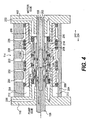
Fig. 4 is a schematic section view of the exemplary valve shown inFig. 2 in a third operational condition; -
Fig. 5 is a schematic section view of the exemplary valve shown inFig. 2 in a fourth operational condition; -
Fig. 6 is a schematic perspective view of an exemplary embodiment of a valve; -
Fig. 7 is a schematic, block diagram of an exemplary embodiment of a dispensing circuit, including an exemplary embodiment of a fluid-powered proportioning pump; and -
Fig. 8 is a schematic, block diagram of an exemplary embodiment of a dispensing circuit including an exemplary embodiment of a fluid-powered proportioning pump. - Reference will now be made in detail to exemplary embodiments of the invention. Wherever possible, the same reference numbers are used in the drawings and the description to refer to the same or like parts.
-
Fig. 1 schematically depicts an exemplary embodiment of afluid motor 10 and an exemplary embodiment of afluid pump 20. Theexemplary fluid motor 10 includesend cap 100,shaft 106,cylindrical motor case 108,end cap 102, andpiston 104. Avariable volume chamber 112 is formed byend cap 102,piston 104, andcase 108. Anothervariable volume chamber 110 is formed byend cap 100,piston 104, andcase 108. - An
exemplary valve assembly 114 operably associated with thefluid motor 10 and thefluid pump 20 is shown inFig. 1 . Theexemplary valve assembly 114 is a shaft position-responsive, pilot-operated, four-way valve. (For clarity, a manifold providing communication between thefluid motor 10 and thevalve assembly 114 is not shown, but exemplary fluid paths are shown schematically.) Thevalve assembly 114 includes aninlet port 136 and aninlet port 138, which communicate within and then through the manifold. The valve assembly further includes anoutlet port 140, which communicates through the manifold. - The
exemplary fluid motor 10 includes achamber 110, which communicates withvalve assembly 114 via apassageway 144 included in the manifold. Thefluid motor 10 also includes achamber 112, which communicates with thevalve assembly 114 via apassageway 142 in the manifold. - The
exemplary fluid pump 20 includes anend cap 118, ashaft 106, acylindrical motor case 120, anend cap 116, and apiston 130. Thefluid pump 20 includes avariable volume chamber 132 formed byend cap 118,piston 130, andcase 120, and avariable volume chamber 134 formed by theend cap 116, thepiston 130, and thecase 120. Apump inlet port 122 communicates with thechamber 132 and thechamber 134 via amanifold 126 andcheck valves 146. Apump outlet port 124 communicates with thechamber 132 and thechamber 134 via amanifold 128 andcheck valves 146. Theshaft 106 extends from thefluid motor 10 through thevalve assembly 114 to thefluid pump 20. Althoughshaft 106 is shown penetratingend cap 118, it could alternatively terminate at thepiston 130. Although theshaft 106 is shown penetrating theend cap 100, it could alternatively terminate at thepiston 104. During exemplary operation, a first fluid enters an inlet port of valve manifold (not shown) to thevalve inlet port 136 and thevalve inlet port 138, where it is directed by thevalve assembly 114 to eithermotor chamber 112 ormotor chamber 110. -
Fig. 2 is a schematic section view of an exemplary embodiment of thevalve assembly 114 shown in an operational condition in which theshaft 106 is positioned at an extreme position toward thefluid motor 10. The exemplary valve assembly is a multi-port valve assembly, which includes concentric elements:shafts 106, ashaft connector 207, a first-stage valve spool 210, aninner valve element 208, a second-stage valve spool 206, and anouter valve element 204. Theexemplary valve assembly 114 includes amotor end cap 102, and anend cap 116. According to some embodiments, the valve elements use static and dynamic seals, such as, for example, o-rings that are shown but not specifically identified. Of these valve assembly elements, theshafts 106, first-stage valve spool 210, and second-stage valve spool 206 are configured to reciprocate within thevalve assembly 114. As shown inFig. 2 , the first-stage valve spool 210 and the second-stage valve spool 206 are positioned toward tofluid motor 10 to illustrate one exemplary operational condition. - According to the exemplary embodiment, a variable
volume valve chamber 212 is formed byouter valve element 204, secondstage valve spool 206,end cap 116, andinner valve element 208. A variablevolume valve chamber 214 is formed byouter valve element 204, secondstage valve spool 206,motor end cap 102, andinner valve element 208. As will be explained in more detail below, ports and passageways are used to achieve a reciprocating function of thefluid motor 10. A motor inlet communicates through a manifold (not shown) tovalve inlet port 226 andvalve inlet port 234. A motor outlet communicates through a manifold (not shown) tovalve outlet port 230.Valve motor port 228 communicates through a manifold (not shown) throughpassageway 142 tomotor chamber 112.Valve motor port 232 communicates through a manifold (not shown) throughpassageway 144 tomotor chamber 110. Apassageway 220 communicates selectively with variablevolume valve chamber 212 through a manifold (not shown) to a high pressure source. - Selective communication is determined by position of first-
stage valve spool 210. Apassageway 222 communicates selectively with variablevolume valve chamber 214 through a manifold (not shown) to a high pressure source. Selective communication is determined by position of first-stage valve spool 210. The motor inlet pressure may provide the high pressure forpassageway 220 andpassageway 222 via a manifold (not shown). Alternatively, the pressure source may be from a source separate from a first powering fluid. - Via a manifold (not shown) in flow communication with a low pressure source, a
passageway 202 withinshaft 106 communicates selectively with variablevolume valve chamber 214 and/orvariable volume chamber 212 throughshaft ports 236. Selective communication may be determined by the position of first-stage valve spool 210. The motor outlet pressure may provide the low pressure forpassageway 202 by means of a manifold (not shown). Alternatively, or in addition, the pressure source may be provided by a source separate from a first powering fluid, such as, for example, venting to drain or to atmosphere. - When, for example,
shaft 106 approaches the limit of its travel, oneshaft shoulder 216 or theother shaft shoulder 218 contacts firststage valve spool 210 and shifts it. As thespool 210 shifts, the configuration of internal ports and passages change, eventually leading to a pressure reversal invalve chamber 214 andvalve chamber 212. The pressure reversal invalve chamber 214 andvalve chamber 212 causes second-stage spool valve 206 to shift. A shift in second-stage spool valve 206 changes the configuration of ports and passages, leading to a flow reversal of a first powering fluid to and frommotor chamber 112 andmotor chamber 110. A flow reversal in afluid motor 10 causes a reversal in travel direction inmotor piston 104 andshaft 106. This reversal, in turn, defines a limit of travel in one direction. This cycle repeats asshaft 106 approaches the other limit of travel. In particular, a first-stage spool valve 210 responds to a shaft position. A second-stage spool valve 206 responds to a position of a first-stage spool valve 210. Apiston 104 andshaft 106 of a fluid motor responds to a position of a second-stage spool valve 206. - Operation of the
valve assembly 114 may be understood with reference toFigs. 3 ,4 , and5 , which schematically depict exemplary flow and pressure changes inexemplary valve assembly 114 by showing the changing positions of ashaft 106, first-stage spool valve 210, and second-stage spool valve 204. For example, as shown inFig. 2 ,shaft 106, second-stage spool valve 206, and first-stage spool valve 210 are at extreme positions in the direction of arrow 242 (i.e., toward the fluid motor 10). The subsequent movement ofshaft 106 is in the direction ofarrow 224. - During exemplary operation, a first powering fluid enters an inlet port through a manifold (not shown), flows to
valve port 234, and communicates withvalve port 232 as a result of a passageway created by the position of second-stage valve spool 206. A powering fluid then flows through a manifold (not shown) tomotor chamber 110. Themotor chamber 110 expands andmotor chamber 112 contracts. The displaced fluid ofchamber 112 flows through a manifold (not shown) tovalve port 228, and then to port 230 as a result of a passageway created by position of the second-stage valve spool 206. The displaced fluid then flows through a manifold (not shown) to an outlet port (not shown).Port 226 is also in communication with a powering fluid. However, the flow is blocked because no passageway has been created by second-stage valve spool 206. Inlet pressure (i.e., a relatively higher pressure) communicates withchamber 212 throughpassageway 220 and throughport 244 ininner valve element 208. Discharge pressure (i.e., a relatively lower pressure) communicates withchamber 214 throughpassageway 202 withinshaft 106, throughshaft port 236, throughspool valve port 240, and through innervalve element port 238. The resulting pressure imbalance causes an unbalanced force, thereby positioning second-stage valve spool 206 in its extreme position in the direction of arrow 242 (i.e., toward fluid motor 10). Inlet pressure (i.e., a relatively higher pressure) is blocked from communicating withchamber 214 because the position of first-stage spool valve 210 results in no passageway for the fluid. -
Fig. 3 is a schematic section view of the exemplary valve shown inFig. 2 in a second operational condition with theshaft 106 at an intermediate position, the first-stage valve spool 210 at an extreme position toward thefluid motor 10, and the second-stage valve spool 206 at an extreme position toward thefluid motor 10. As shown inFig. 3 , the second-stage spool valve 206 and the first-stage spool valve 210 are at their extreme position in direction ofarrow 242, and theshaft 106 has moved to an intermediate position in the direction ofarrow 224 toward thefluid pump 20. Ashaft shoulder 216 makes contact with first-stage spool valve 210. Further movement of theshaft 106 in adirection 224 will result in movement of the first-stage spool valve 210 in direction ofarrow 224. The movement of theshaft 106 is in the direction of thearrow 224. - During exemplary operation, a first powering fluid enters an inlet port through a manifold (not shown) to the
valve port 234 and communicates with thevalve port 232 as a result of a passageway created by position of second-stage valve spool 206. A powering fluid then flows through a manifold (not shown) tomotor chamber 110.Motor chamber 110 expands andmotor chamber 112 contracts. The displaced fluid ofchamber 112 flows through a manifold (not shown) tovalve port 228 and then to port 230 as a result of a passageway created by position of the second-stage valve spool 206. The displaced fluid then flows through a manifold (not shown) to an outlet port (not shown).Port 226 is also in communication with a powering fluid. However, the flow is blocked toport 226 because no passageway has been created by second-stage valve spool 206. Inlet pressure (i.e., a relatively higher pressure) communicates with thechamber 212 throughpassageway 220 and throughport 244 ininner valve element 208. Discharge pressure (i.e., a relatively lower pressure) communicates with thechamber 214 throughpassageway 202 withinshaft 106, throughshaft port 236, throughspool valve port 240, and through innervalve element port 238. The resulting pressure imbalance causes and unbalanced force, thereby positioning second-stage valve spool 206 in its extreme position in the direction ofarrow 242. Inlet pressure (i.e., a relatively higher pressure) is blocked from communicating withchamber 214 because the position of first-stage valve spool 210 results in no passageway. -
Fig. 4 is a schematic section view of theexemplary valve assembly 114 shown inFig. 2 in a third operational condition with theshaft 106 positioned toward thefluid pump 20, first-stage valve spool 210 positioned toward thefluid pump 20, and the second-stage valve spool 206 positioned toward thefluid motor 10. In particular,shaft 106 and first-stage valve spool 210 are at their extreme position in direction ofarrow 224, and second-stage valve spool 206 is in an extreme position in the direction ofarrow 242. Second-stage valve spool 206 is just beginning to move in the direction ofarrow 224. Ashaft shoulder 216 makes contact with the first-stage valve spool 210, and further movement of theshaft 106 in the direction ofarrow 224 is not possible because it is at the limit of its travel. The direction of movement ofshaft 106 is about to reverse in the direction ofarrow 242. - During exemplary operation, a first powering fluid enters an inlet port through a manifold (not shown) to
valve port 234 and communicates withvalve port 232 as a result of a passageway created by the position of the second-stage valve spool 206. A powering fluid then flows through a manifold (not shown) tomotor chamber 110.Motor chamber 110 expands, andmotor chamber 112 contracts. The displaced fluid ofmotor chamber 112 flows through a manifold (not shown) tovalve port 228 and then to port 230 as a result of a passageway created by the position of the second-stage valve spool 206. The displaced fluid then flows through a manifold (not shown) to an outlet port (not shown).Port 226 is also in communication with a powering fluid. However, the flow is blocked because no passageway has been created by the second-stage valve spool 206. Inlet pressure (i.e., a relatively higher pressure) communicates withchamber 214 throughpassageway 222 and throughport 238 invalve element 208. Discharge pressure (i.e., a relatively lower pressure) communicates withchamber 212 throughpassageway 202 withinshaft 106, throughshaft port 236, throughspool valve port 240, and through innervalve element port 244. The resulting pressure imbalance causes an unbalanced force, which causes the second-stage valve spool 206 to shift in the direction ofarrow 224. Inlet pressure (i.e., a relatively higher pressure) is blocked from communicating withchamber 212 because the position of the first-stage spool valve 210 results in no passageway. -
Fig. 5 is a schematic section view of the exemplary valve shown inFig. 2 in a fourth operational condition, with theshaft 106 located at an extreme position toward thefluid pump 20, the first-stage valve spool 210 located at an extreme position toward thefluid pump 20, and the second-stage valve spool 206 located at an extreme position toward thefluid pump 20. In particular, theshaft 106, the second-stage spool valve 206, and the first-stage spool valve 210 are at their extreme position in the direction ofarrow 224, and theshaft 106 is beginning to move in the reverse direction, (i.e., in the direction of arrow 242). Theshaft 106 travels a distance before theshaft shoulder 218 makes contact with first-stage valve spool 210. - During exemplary operation, a first powering fluid enters an inlet port through a manifold (not shown) to
valve port 226 and communicates withvalve port 228 as a result of a passageway created by the position of second-stage valve spool 206. A powering fluid then flows through a manifold (not shown) tomotor chamber 112. Themotor chamber 112 expands, and themotor chamber 110 contracts. The displaced fluid ofmotor chamber 110 flows through a manifold (not shown) tovalve port 232 and then to port 230 as a result of a passageway created by the position of second-stage valve spool 206. The displaced fluid then flows through a manifold (not shown) to an outlet port (not shown).Port 234 is also in flow communication with a powering fluid. However, the flow is blocked because no passageway has been created by the second-stage valve spool 206. Inlet pressure (i.e., a relatively higher pressure) communicates withchamber 214 throughpassageway 222 and throughport 238 invalve element 208. Discharge pressure (i.e., a relatively lower pressure) communicates withchamber 212 throughpassageway 202 within theshaft 106, throughshaft port 236, throughspool valve port 240, and through innervalve element port 244. The resulting pressure imbalance causes and unbalanced force, which positions second-stage valve spool 206 in its extreme position in the direction ofarrow 224. Inlet pressure (i.e., a relatively higher pressure) is blocked from communicating withchamber 212 because the position of first-stage valve spool 210 results in no passageway. - The first-
stage valve spool 210 reverses the actuating pressure on the second-stage valve spool 206 responsive to the position of theshaft 106. As first-stage valve spool 210 travels between its limits of travel, it will create a null state where neither high pressure nor low pressure communicates withchamber 212 orchamber 214. - According to some embodiments, powering fluids may include powering liquids and/or a powering gas or gases, such as, for example, compressed gas. Thus, the term "fluid" is meant to include any gas, liquid, and/or mixed phase, including gas and liquid.
- According to some embodiments, various static and/or dynamic seals may be incorporated into the fluid motor, fluid pump, and/or valve assembly. For example, gaskets, adhesives, o-rings and/or various combinations may be used for static seals. Close running fits, piston rings, packings, o-rings, lip seals, and/or combinations thereof may be used for dynamic seals of pistons and rods. Other seals may be used.
- According to some embodiments, multiple fluid pumps may be operated via a single fluid motor. For example, in addition to the exemplary fluid pump shown in
Fig. 1 , one or more additional fluid pumps may be added via shaft extensions and/or pistons operating in stacked chambers, for example, via the repetition of pump housings. It should be noted that the chambers and/or pistons need not have the same cross section and/or displacement per stroke. Any type of fluid pump including a reciprocation motion may be suitable for mounting to a fluid motor according to some embodiments. Some examples of such fluid pumps include piston pumps, diaphragm pumps having a diaphragm operable via a reciprocating motion. Other types of fluid pumps may also be used. Although the exemplary valve assembly depicted herein is shown positioned between the fluid pump and the fluid motor, alternative locations may include positioning the valve assembly on one end of a fluid motor and on one end of a fluid pump. -
Fig. 6 is a schematic perspective view of an exemplary embodiment of avalve spool 206. Theexemplary valve spool 206 includes a castellated o-ring groove wall. The exemplaryconcentric valve spool 206 may operate according to one or more of the exemplary descriptions relating toFigs. 2-5 . Theexemplary valve spool 206 defines a hollow, substantially cylindrical shape. Thevalve spool 206 includes aport relief 352, aport relief 350, and aport relief 348. Thevalve spool 206 further includes end o-ring grooves 340. Thevalve spool 206 may further include a first set of o-ring grooves 344 and a second set of o-ring grooves 346. Each set of o-ring grooves includes, for example, three o-ringgrooves having notches 354 forming castellations in the o-ring grooves. Such castellations may reduce the likelihood of, for example, pinching of the o-ring seals as the valve spools 206 and 210 move relative to one another and/or other portions of thevalve assembly 114. - The
exemplary valve spool 206 may be configured to receive, for example, dynamic o-ring seals ingrooves 344 andgrooves 346, which may be biased for expansion out of their respective grooves asvalve spool 206 shifts and extends through a widening space asgrooves 344 and/orgrooves 346 enter a low pressure zone and are no longer confined. When not confined, an o-ring ofgroove 344 and/or groove 346 may begin to expand. This expansion may be countered by a new pressure relief path formed under an o-ring bynotches 354. Thenotches 354 may be configured to be small enough compared to a cross section of an o-ring, so as not to form an extension opportunity themselves. Thenotches 354 may be configured so as to not contribute to leakage as a seal is formed when o-rings are confined by the bottom of an o-ring groove 344 and/or groove 346 and the inner cylindrical surface ofouter valve element 204. -
Fig. 7 is a schematic, block diagram of an exemplary embodiment of a dispensing circuit including an exemplary embodiment of a fluid-powered proportioning pump. The exemplary embodiment shown inFig. 7 includes a single dispenser valve, such as may be used, for example, in post-mix beverage dispensing. The exemplary circuit illustrated anticipates that fluid pressure inline 408 will be higher than fluid pressure inline 424 and that pressure inline 420 is higher than the pressure inline 414. The circuit is configured such that other devices may be included in the circuit before or after the fluid-powered proportion pump, such as devices that add additional components (ingredients) to the powering fluid, the pumped fluid, or both. The exemplary circuit is configured such that powering fluid flow may be stopping and/or starting via devices, including booster pumps, manually-operated valves, and/or power-operated valves (e.g., solenoid valves). Such devices may be responsive to a controller, sensor, and/or limit device. The exemplary circuit is configured to incorporate a fluid-powered proportion unit having multiple pumps, which may proportion multiple additional ingredients. - A fluid-powered proportioning unit may include a
motor section 412, avalve section 416, and apump section 418. According to the exemplary embodiment shown inFig. 7 , a poweringfluid source 400 supplies abooster pump 404 through aline 406. Thebooster pump 404 supplies a pressurized fluid to the fluid-powered proportion unit throughline 408. According to exemplary operation, if the pressure offluid source 400 is already high enough to operate a fluid powering proportioning unit in the system, then thebooster pump 404 may be excluded from the exemplary circuit. A second pumpedfluid source 402 communicates with an inlet ofpump section 418 of a fluid-powered proportioning pump throughline 414. A powering fluid is discharged from a motor throughline 424. A second pumped fluid is discharged throughline 420.Lines 424 andline 420 join to formline 422, which contains a proportioned flow of a first powering fluid and a second pumped fluid that communicates withdispenser outlet 426.Proportioned flow 430 exits the dispenser atdispenser outlet 426 to be received inproduct container 428. According to some embodiments, aline 410 may provide flow communication betweenfluid source 400 andvalve assembly 416, for example, to permit fluid flow to a destination of lower pressure, which may result in greater energy availability for valve operation. - The proportioned flow may be dispensed in alternative ways. For example,
line 424 andline 420 may be configured to deliver respective flows unjoined or unmixed prior to the dispensepoint 426, and mixing could occur as a separate operation. According to some embodiments, a dispense point may be the termination point as a subsystem in a larger system. According to some embodiments, a dispense point may be a nozzle rather than a faucet. The character of dispense point may be determined according to the application needs. -
Fig. 8 is a schematic, block diagram of an exemplary embodiment of a dispensing circuit including an exemplary embodiment of a fluid-powered proportioning pump, wherein the dispenser system includes an array of fluid-powered, proportioning pumps and dispenser valves, such as may be used in, for example, post-mix beverage dispensing systems. According to the exemplary embodiment shown, to provide energy for operation of afluid motor 412 andvalve section 416, the circuit illustrated anticipates that the fluid pressure inline 438 will be higher than the fluid pressure inline 424. The pressure inline 474 is higher than the pressure inline 414, and fluid flow is attained bypump section 418. To provide energy for operation of afluid motor 454 andvalve section 452, the exemplary circuit illustrated anticipates that the fluid pressure inline 440 will be higher than the fluid pressure inline 450. The fluid pressure inline 476 is higher than the pressure inline 448, and fluid flow is attained bypump section 458. - The exemplary circuit is configured such that other devices may be included in the circuit before and/or after the fluid-powered proportioning pump, such as devices that add additional components (ingredients) to the powering fluid, to the pumped fluid, or both. The circuit may be configured to stop and/or start flow of a powering fluid by devices including booster pumps, manually-operated valves, and power-operated valves (e.g., solenoid valves). Such devices may be configured to be responsive to a controller, sensor, and/or limit device. The circuit may be configured to include a fluid-powered proportioning unit having, for example, multiple pumps that may proportion multiple additional ingredients.
- According to some embodiments, a fluid-powered proportioning unit includes a
fluid motor section 412, avalve assembly 416, and apump section 418. A poweringfluid source 400 supplies abooster pump 404 throughline 406, and thebooster pump 404 supplies a pressurized fluid to distribution manifold 470. A branch circuit includes aline 472 branching off of manifold 470. Avalve 436 is configured to interrupt the flow of a first powering fluid, and thevalve 436 may be, for example, a solenoid valve responsive to a dispenser controller (not shown).Line 438 is in flow communication withvalve assembly 416 and subsequentlymotor section 412. - During exemplary operation, if the pressure of
fluid source 400 is already high enough to operate a fluid powering proportioning unit in the application, then thebooster pump 404 may be excluded from the circuit. A second pumpedfluid source 402 is in flow communication with an inlet ofpump section 418 of a fluid-powered proportioning pump throughline 414. A powering fluid is discharged from a fluid motor throughline 424. A second pumped fluid is discharged throughline 474.Lines 424 andline 474 join to formline 422, which may contain a proportioned flow of a first powering fluid and a second pumped fluid that entersaccumulator 434. Theaccumulator 434 allows dispensing of a proportioned flow without the necessity of operation of a fluid-powered proportioning pump. Theaccumulator 434 may include a pressure switch to which a dispenser controller responds. Theaccumulator 434 may be of a type, such as, for example, a freezer barrel for frozen drinks. - According to exemplary operation, when
dispenser valve 426 is opened, proportioned product flows from theaccumulator 434, throughline 432, throughdispenser valve 426, and intoproduct container 428. - According to some embodiments, a branch circuit begins from
line 444 extending from the manifold 470. Avalve 442 interrupts the flow of a first powering fluid. Thevalve 442 may be, for example, a solenoid valve responsive to a dispenser controller (not shown).Line 440 is in flow communication with thevalve section 452 and subsequently themotor section 454. - If the pressure of the
fluid source 400 is already high enough to operate a fluid-powered proportioning unit for the application, then thebooster pump 404 may be excluded from the circuit. A second pumpedfluid source 446 is in flow communication with an inlet ofpump section 458 of a fluid-powered proportioning pump throughline 448. A powering fluid is discharged from a motor throughline 450, and a second pumped fluid is discharged throughline 476.Lines 450 andline 476 join to formline 456, which contains a proportioned flow of a first powering fluid and a second pumped fluid that enters anaccumulator 458. Theaccumulator 458 permits dispensing of a proportioned flow without the necessity of operation of a fluid-powered proportioning pump. Theaccumulator 434 may be of a specialized type, such as, for example, a carbonator, and may include a high-low level switch to which a dispenser controller responds. During exemplary operation, when the dispensevalve 466 is opened, proportioned product flows from accumulator/carbonator 458 throughline 464, throughdispenser valve 466, and intoproduct container 468. Carbon dioxide gas enterscarbonator 458 throughline 460 from pressurizedcarbon dioxide source 462. - It will be apparent to those skilled in the art that various modifications and variations can be made to the structures and methodologies described herein. Thus, it should be understood that the invention is not limited to the subject matter discussed in the description. Rather, the present invention is intended to cover modifications and variations, within the scope of the appended claims.
Claims (9)
- A fluid-powered proportioning pump, for controlling flow of relative amounts of one or two fluids, comprising:• a fluid motor (10) configured to convert fluid flow into mechanical work, the motor (10) comprising a first chamber (112), a second chamber (110), a piston (104) separating the first chamber (112) and the second chamber (110) from one another, the motor piston (104) being configured to reciprocate, and a shaft (106) operably coupled to the motor piston (104);• a valve assembly (114) configured to selectively control flow of fluid to the first chamber (112) and the second chamber (110), the valve assembly (114) comprising a housing, a portion (207) of the shaft (106) configured to operably couple the valve assembly (114) to the motor (10), a first-stage valve spool (210) configured to reciprocate within the valve housing in response to fluid flowing into the valve assembly (114) and movement of the shaft portion (207), and a second-stage valve spool (206) configured to reciprocate within the valve housing in response to fluid flowing into the valve assembly (114) and movement of the first-stage valve spool (210); and• a fluid pump (20) operably coupled to the motor (10) and the valve assembly (114) through the shaft (106), the pump (20) comprising a housing (120) and a pump piston (130) configured to reciprocate within the pump housing (120), the shaft (106) being operably coupled to the pump piston (130), characterized in that the valve housing, the shaft (106), the shaft portion (207), the first-stage valve spool (210) and the second-stage valve spool (206) form a nested relationship and are concentric with respect to one another, the first-stage valve spool (210) and the second-stage valve spool (206) being shifted by a powering fluid entering the valve assembly (114) to selectively control the flow of fluid into the first chamber (112) and the second chamber (110) of the motor (10) such that the motor piston (104) reciprocates, thereby causing reciprocation of the shaft (106) for moving the pump piston (130).
- The fluid-powered proportioning pump of claim 1, wherein the valve assembly (114) is configured such that as fluid flows into the first chamber (112), the motor piston (104) moves toward the second chamber (110), thereby causing the shaft (106) to move in a first direction.
- The fluid-powered proportioning pump of claim 2, wherein when the shaft (106) moves in the first direction, the first-stage valve spool (210) is moved in the first direction.
- The fluid-powered proportioning pump of claim 3, wherein when the first-stage valve spool (210) reaches an end of travel in the first direction, the second-stage valve spool (206) moves in the first direction.
- The fluid-powered proportioning pump of claim 3, wherein when the second-stage valve spool (206) reaches an end of travel in the first direction, fluid flow is directed into the second chamber (110) such that the motor piston (104) moves toward the first chamber (112) and the shaft (106) moves in a second direction.
- The fluid-powered proportioning pump of claim 1, wherein the pump piston (130) separates the pump housing (120) into a first pump chamber (132) and a second pump chamber (134).
- The fluid-powered proportioning pump of claim 6, wherein the first pump chamber (132) and the second pump chamber (134) each comprise an inlet orifice, configured to draw fluid into the respective pump chamber (132, 134) as the pump piston (130) moves to expand the respective pump chamber (132, 134), and an outlet orifice configured to expel fluid out of the respective pump chamber (132, 134) as the pump piston (130) moves to contract the respective pump chamber (132, 134).
- The fluid-powered proportioning pump of claim 1, wherein a first fluid flows into the motor (10) and a second fluid is pumped by the fluid pump (20), the flow of the first fluid into the motor (10) and the second fluid pumped by the fluid pump (20) resulting in a proportion being substantially maintained between the volume of the first fluid flowing into the motor (10) and the volume of the second fluid pumped by the fluid pump (20).
- The fluid-powered proportioning pump of claim 1, wherein at least one of the first-stage valve spool (210) and the second-stage valve spool (206) comprises one or more grooves (340, 344, 346) each configured to receive a seal, and wherein each groove (340, 344, 346) defines notches (354) configured to reduce the likelihood of pinching of the seal.
Applications Claiming Priority (2)
| Application Number | Priority Date | Filing Date | Title |
|---|---|---|---|
| US83179206P | 2006-07-19 | 2006-07-19 | |
| PCT/IB2007/003616 WO2008029288A2 (en) | 2006-07-19 | 2007-07-19 | Fluid-powered proportioning pump and system for dispensing fluid inluding such a pump |
Publications (2)
| Publication Number | Publication Date |
|---|---|
| EP2041396A2 EP2041396A2 (en) | 2009-04-01 |
| EP2041396B1 true EP2041396B1 (en) | 2011-09-14 |
Family
ID=39157634
Family Applications (1)
| Application Number | Title | Priority Date | Filing Date |
|---|---|---|---|
| EP07848937A Not-in-force EP2041396B1 (en) | 2006-07-19 | 2007-07-19 | Fluid-powered proportioning pump and system for dispensing fluid including such a pump |
Country Status (8)
| Country | Link |
|---|---|
| EP (1) | EP2041396B1 (en) |
| JP (1) | JP2009543981A (en) |
| KR (1) | KR20090040444A (en) |
| CN (1) | CN101512104B (en) |
| AT (1) | ATE524636T1 (en) |
| CA (1) | CA2657567A1 (en) |
| ES (1) | ES2373593T3 (en) |
| WO (1) | WO2008029288A2 (en) |
Cited By (1)
| Publication number | Priority date | Publication date | Assignee | Title |
|---|---|---|---|---|
| WO2013115934A1 (en) * | 2012-01-31 | 2013-08-08 | Hammonds Technical Services, Inc. | Fluid additive delivery system with flow meter |
Families Citing this family (12)
| Publication number | Priority date | Publication date | Assignee | Title |
|---|---|---|---|---|
| CN101929449A (en) * | 2010-09-07 | 2010-12-29 | 济南赛思特流体系统设备有限公司 | Hydraulic drive liquid booster pump |
| US9644761B2 (en) | 2011-09-30 | 2017-05-09 | General Electric Company | Desalination system with energy recovery and related pumps, valves and controller |
| US9387440B2 (en) | 2011-09-30 | 2016-07-12 | General Electric Company | Desalination system with energy recovery and related pumps, valves and controller |
| US9897080B2 (en) | 2012-12-04 | 2018-02-20 | General Electric Company | Rotary control valve for reverse osmosis feed water pump with energy recovery |
| US9638179B2 (en) | 2012-12-04 | 2017-05-02 | General Electric Company | Hydraulic control system for a reverse osmosis hydraulic pump |
| CA3035610A1 (en) * | 2016-10-12 | 2018-04-19 | Energy Harvest As | Rotary valve device and liquid lifting device comprising the same |
| JP6598839B2 (en) * | 2017-11-17 | 2019-10-30 | 東レエンジニアリング株式会社 | Intermittent application device |
| NL2021527B1 (en) * | 2018-08-30 | 2020-04-24 | Holmatro B V | Tool having a pump and a motor on a common axis |
| CN110206590A (en) * | 2019-05-23 | 2019-09-06 | 重庆海骏克科技有限公司 | A kind of free plunger expanding machine and hydraulic power generating unit |
| CN111732065A (en) * | 2020-07-22 | 2020-10-02 | 湖南广盛源医药科技有限公司 | A racking machine for hydrogen peroxide antiseptic solution production line |
| CN112112793B (en) * | 2020-09-15 | 2023-02-17 | 秦皇岛卓飞科技有限公司 | Large-flow ultrahigh-pressure hydraulic pump |
| RO135554A2 (en) * | 2020-09-16 | 2022-03-30 | Institutul Naţional De Cercetare-Dezvoltare Pentru Optoelectronică - Inoe 2000 Ihp - Filiala Institutul De Cercetări | Autonomous pumping device for fertigation |
Family Cites Families (3)
| Publication number | Priority date | Publication date | Assignee | Title |
|---|---|---|---|---|
| US3700360A (en) * | 1971-08-23 | 1972-10-24 | Myers Sherman Co | Double-acting tandem piston pump |
| NO170236C (en) * | 1989-04-06 | 1992-09-23 | Speeder As | LINEAERMOTOR |
| US6769884B2 (en) * | 2000-12-11 | 2004-08-03 | Cory L. Miller | Hydraulic drive system for piston pumps |
-
2007
- 2007-07-19 CA CA002657567A patent/CA2657567A1/en not_active Abandoned
- 2007-07-19 EP EP07848937A patent/EP2041396B1/en not_active Not-in-force
- 2007-07-19 JP JP2009520075A patent/JP2009543981A/en active Pending
- 2007-07-19 ES ES07848937T patent/ES2373593T3/en active Active
- 2007-07-19 AT AT07848937T patent/ATE524636T1/en active
- 2007-07-19 WO PCT/IB2007/003616 patent/WO2008029288A2/en active Application Filing
- 2007-07-19 KR KR1020097003392A patent/KR20090040444A/en not_active Application Discontinuation
- 2007-07-19 CN CN2007800326983A patent/CN101512104B/en not_active Expired - Fee Related
Cited By (3)
| Publication number | Priority date | Publication date | Assignee | Title |
|---|---|---|---|---|
| WO2013115934A1 (en) * | 2012-01-31 | 2013-08-08 | Hammonds Technical Services, Inc. | Fluid additive delivery system with flow meter |
| US8627728B2 (en) | 2012-01-31 | 2014-01-14 | Hammonds Technical Services, Inc. | System for determining the flow rate in a fluid with liquid additives using reciprocating positive-displacement flow meter |
| US8695434B2 (en) | 2012-01-31 | 2014-04-15 | Hammonds Technical Services, Inc. | Fluid additive delivery system powered by the flowing fluid |
Also Published As
| Publication number | Publication date |
|---|---|
| WO2008029288A3 (en) | 2008-10-30 |
| EP2041396A2 (en) | 2009-04-01 |
| CA2657567A1 (en) | 2008-03-13 |
| JP2009543981A (en) | 2009-12-10 |
| ATE524636T1 (en) | 2011-09-15 |
| WO2008029288A2 (en) | 2008-03-13 |
| CN101512104A (en) | 2009-08-19 |
| CN101512104B (en) | 2012-08-22 |
| ES2373593T3 (en) | 2012-02-06 |
| KR20090040444A (en) | 2009-04-24 |
Similar Documents
| Publication | Publication Date | Title |
|---|---|---|
| EP2041396B1 (en) | Fluid-powered proportioning pump and system for dispensing fluid including such a pump | |
| US4684332A (en) | Ratio pump and method | |
| US4540349A (en) | Air driven pump | |
| US4927567A (en) | Motorless continuous carbonator | |
| EP1517037A2 (en) | A fluid transfer device | |
| US4966306A (en) | Beverage dispenser system using volumetric ratio control device | |
| US6712242B2 (en) | Fluid dispensing system and dual-mode, system fluid actuated valve for use therein | |
| US4349130A (en) | Liquid metering pump | |
| US4507054A (en) | Liquid dispensing system | |
| US4953754A (en) | Beverage dispenser system using volumetric ratio control device | |
| US5470209A (en) | Offset reciprocable device | |
| US7278836B2 (en) | Metering pump | |
| US11378433B2 (en) | Manifold style metering mechanism for use with beverage dispensing system | |
| US6840406B2 (en) | Proportional volumetric injector-dispenser | |
| US11143173B2 (en) | Hydraulically synchronized pumps where the hydraulic motor of the master pump hydraulically drives the hydraulic motor of the slave pump | |
| KR101044376B1 (en) | Pump apparatus | |
| CN217708882U (en) | Extraction gun and extraction system comprising same | |
| CA2485390A1 (en) | Fluid dispensing system and dual-mode, system fluid actuated valve for use therein | |
| CN117185240A (en) | Extraction gun and extraction system comprising same | |
| NZ206142A (en) | Spool valve:body contains seal pockets at each end,and insertable sleeve |
Legal Events
| Date | Code | Title | Description |
|---|---|---|---|
| PUAI | Public reference made under article 153(3) epc to a published international application that has entered the european phase |
Free format text: ORIGINAL CODE: 0009012 |
|
| 17P | Request for examination filed |
Effective date: 20090116 |
|
| AK | Designated contracting states |
Kind code of ref document: A2 Designated state(s): AT BE BG CH CY CZ DE DK EE ES FI FR GB GR HU IE IS IT LI LT LU LV MC MT NL PL PT RO SE SI SK TR |
|
| AX | Request for extension of the european patent |
Extension state: AL BA HR MK RS |
|
| 17Q | First examination report despatched |
Effective date: 20090603 |
|
| DAX | Request for extension of the european patent (deleted) | ||
| GRAP | Despatch of communication of intention to grant a patent |
Free format text: ORIGINAL CODE: EPIDOSNIGR1 |
|
| GRAS | Grant fee paid |
Free format text: ORIGINAL CODE: EPIDOSNIGR3 |
|
| GRAA | (expected) grant |
Free format text: ORIGINAL CODE: 0009210 |
|
| AK | Designated contracting states |
Kind code of ref document: B1 Designated state(s): AT BE BG CH CY CZ DE DK EE ES FI FR GB GR HU IE IS IT LI LT LU LV MC MT NL PL PT RO SE SI SK TR |
|
| REG | Reference to a national code |
Ref country code: GB Ref legal event code: FG4D |
|
| REG | Reference to a national code |
Ref country code: CH Ref legal event code: EP |
|
| REG | Reference to a national code |
Ref country code: IE Ref legal event code: FG4D |
|
| REG | Reference to a national code |
Ref country code: DE Ref legal event code: R096 Ref document number: 602007017266 Country of ref document: DE Effective date: 20111208 |
|
| REG | Reference to a national code |
Ref country code: CH Ref legal event code: NV Representative=s name: AMMANN PATENTANWAELTE AG BERN |
|
| REG | Reference to a national code |
Ref country code: NL Ref legal event code: T3 |
|
| PG25 | Lapsed in a contracting state [announced via postgrant information from national office to epo] |
Ref country code: FI Free format text: LAPSE BECAUSE OF FAILURE TO SUBMIT A TRANSLATION OF THE DESCRIPTION OR TO PAY THE FEE WITHIN THE PRESCRIBED TIME-LIMIT Effective date: 20110914 Ref country code: LT Free format text: LAPSE BECAUSE OF FAILURE TO SUBMIT A TRANSLATION OF THE DESCRIPTION OR TO PAY THE FEE WITHIN THE PRESCRIBED TIME-LIMIT Effective date: 20110914 Ref country code: SE Free format text: LAPSE BECAUSE OF FAILURE TO SUBMIT A TRANSLATION OF THE DESCRIPTION OR TO PAY THE FEE WITHIN THE PRESCRIBED TIME-LIMIT Effective date: 20110914 |
|
| REG | Reference to a national code |
Ref country code: ES Ref legal event code: FG2A Ref document number: 2373593 Country of ref document: ES Kind code of ref document: T3 Effective date: 20120206 |
|
| LTIE | Lt: invalidation of european patent or patent extension |
Effective date: 20110914 |
|
| PG25 | Lapsed in a contracting state [announced via postgrant information from national office to epo] |
Ref country code: LV Free format text: LAPSE BECAUSE OF FAILURE TO SUBMIT A TRANSLATION OF THE DESCRIPTION OR TO PAY THE FEE WITHIN THE PRESCRIBED TIME-LIMIT Effective date: 20110914 Ref country code: CY Free format text: LAPSE BECAUSE OF FAILURE TO SUBMIT A TRANSLATION OF THE DESCRIPTION OR TO PAY THE FEE WITHIN THE PRESCRIBED TIME-LIMIT Effective date: 20110914 Ref country code: GR Free format text: LAPSE BECAUSE OF FAILURE TO SUBMIT A TRANSLATION OF THE DESCRIPTION OR TO PAY THE FEE WITHIN THE PRESCRIBED TIME-LIMIT Effective date: 20111215 Ref country code: SI Free format text: LAPSE BECAUSE OF FAILURE TO SUBMIT A TRANSLATION OF THE DESCRIPTION OR TO PAY THE FEE WITHIN THE PRESCRIBED TIME-LIMIT Effective date: 20110914 |
|
| PG25 | Lapsed in a contracting state [announced via postgrant information from national office to epo] |
Ref country code: IS Free format text: LAPSE BECAUSE OF FAILURE TO SUBMIT A TRANSLATION OF THE DESCRIPTION OR TO PAY THE FEE WITHIN THE PRESCRIBED TIME-LIMIT Effective date: 20120114 Ref country code: SK Free format text: LAPSE BECAUSE OF FAILURE TO SUBMIT A TRANSLATION OF THE DESCRIPTION OR TO PAY THE FEE WITHIN THE PRESCRIBED TIME-LIMIT Effective date: 20110914 Ref country code: CZ Free format text: LAPSE BECAUSE OF FAILURE TO SUBMIT A TRANSLATION OF THE DESCRIPTION OR TO PAY THE FEE WITHIN THE PRESCRIBED TIME-LIMIT Effective date: 20110914 |
|
| PG25 | Lapsed in a contracting state [announced via postgrant information from national office to epo] |
Ref country code: PL Free format text: LAPSE BECAUSE OF FAILURE TO SUBMIT A TRANSLATION OF THE DESCRIPTION OR TO PAY THE FEE WITHIN THE PRESCRIBED TIME-LIMIT Effective date: 20110914 Ref country code: EE Free format text: LAPSE BECAUSE OF FAILURE TO SUBMIT A TRANSLATION OF THE DESCRIPTION OR TO PAY THE FEE WITHIN THE PRESCRIBED TIME-LIMIT Effective date: 20110914 Ref country code: PT Free format text: LAPSE BECAUSE OF FAILURE TO SUBMIT A TRANSLATION OF THE DESCRIPTION OR TO PAY THE FEE WITHIN THE PRESCRIBED TIME-LIMIT Effective date: 20120116 Ref country code: RO Free format text: LAPSE BECAUSE OF FAILURE TO SUBMIT A TRANSLATION OF THE DESCRIPTION OR TO PAY THE FEE WITHIN THE PRESCRIBED TIME-LIMIT Effective date: 20110914 |
|
| PLBE | No opposition filed within time limit |
Free format text: ORIGINAL CODE: 0009261 |
|
| STAA | Information on the status of an ep patent application or granted ep patent |
Free format text: STATUS: NO OPPOSITION FILED WITHIN TIME LIMIT |
|
| PG25 | Lapsed in a contracting state [announced via postgrant information from national office to epo] |
Ref country code: DK Free format text: LAPSE BECAUSE OF FAILURE TO SUBMIT A TRANSLATION OF THE DESCRIPTION OR TO PAY THE FEE WITHIN THE PRESCRIBED TIME-LIMIT Effective date: 20110914 |
|
| 26N | No opposition filed |
Effective date: 20120615 |
|
| REG | Reference to a national code |
Ref country code: DE Ref legal event code: R097 Ref document number: 602007017266 Country of ref document: DE Effective date: 20120615 |
|
| PG25 | Lapsed in a contracting state [announced via postgrant information from national office to epo] |
Ref country code: MC Free format text: LAPSE BECAUSE OF NON-PAYMENT OF DUE FEES Effective date: 20120731 |
|
| REG | Reference to a national code |
Ref country code: IE Ref legal event code: MM4A |
|
| PG25 | Lapsed in a contracting state [announced via postgrant information from national office to epo] |
Ref country code: BG Free format text: LAPSE BECAUSE OF FAILURE TO SUBMIT A TRANSLATION OF THE DESCRIPTION OR TO PAY THE FEE WITHIN THE PRESCRIBED TIME-LIMIT Effective date: 20111214 |
|
| PG25 | Lapsed in a contracting state [announced via postgrant information from national office to epo] |
Ref country code: IE Free format text: LAPSE BECAUSE OF NON-PAYMENT OF DUE FEES Effective date: 20120719 Ref country code: MT Free format text: LAPSE BECAUSE OF FAILURE TO SUBMIT A TRANSLATION OF THE DESCRIPTION OR TO PAY THE FEE WITHIN THE PRESCRIBED TIME-LIMIT Effective date: 20110914 |
|
| PGFP | Annual fee paid to national office [announced via postgrant information from national office to epo] |
Ref country code: CH Payment date: 20130712 Year of fee payment: 7 Ref country code: AT Payment date: 20130626 Year of fee payment: 7 Ref country code: BE Payment date: 20130712 Year of fee payment: 7 Ref country code: NL Payment date: 20130710 Year of fee payment: 7 |
|
| PGFP | Annual fee paid to national office [announced via postgrant information from national office to epo] |
Ref country code: FR Payment date: 20130724 Year of fee payment: 7 |
|
| PG25 | Lapsed in a contracting state [announced via postgrant information from national office to epo] |
Ref country code: TR Free format text: LAPSE BECAUSE OF FAILURE TO SUBMIT A TRANSLATION OF THE DESCRIPTION OR TO PAY THE FEE WITHIN THE PRESCRIBED TIME-LIMIT Effective date: 20110914 |
|
| PG25 | Lapsed in a contracting state [announced via postgrant information from national office to epo] |
Ref country code: LU Free format text: LAPSE BECAUSE OF NON-PAYMENT OF DUE FEES Effective date: 20120719 |
|
| PG25 | Lapsed in a contracting state [announced via postgrant information from national office to epo] |
Ref country code: HU Free format text: LAPSE BECAUSE OF FAILURE TO SUBMIT A TRANSLATION OF THE DESCRIPTION OR TO PAY THE FEE WITHIN THE PRESCRIBED TIME-LIMIT Effective date: 20070719 |
|
| REG | Reference to a national code |
Ref country code: NL Ref legal event code: V1 Effective date: 20150201 |
|
| REG | Reference to a national code |
Ref country code: CH Ref legal event code: PL |
|
| REG | Reference to a national code |
Ref country code: AT Ref legal event code: MM01 Ref document number: 524636 Country of ref document: AT Kind code of ref document: T Effective date: 20140719 |
|
| PG25 | Lapsed in a contracting state [announced via postgrant information from national office to epo] |
Ref country code: NL Free format text: LAPSE BECAUSE OF NON-PAYMENT OF DUE FEES Effective date: 20150201 |
|
| REG | Reference to a national code |
Ref country code: FR Ref legal event code: ST Effective date: 20150331 |
|
| PG25 | Lapsed in a contracting state [announced via postgrant information from national office to epo] |
Ref country code: CH Free format text: LAPSE BECAUSE OF NON-PAYMENT OF DUE FEES Effective date: 20140731 Ref country code: LI Free format text: LAPSE BECAUSE OF NON-PAYMENT OF DUE FEES Effective date: 20140731 |
|
| PG25 | Lapsed in a contracting state [announced via postgrant information from national office to epo] |
Ref country code: AT Free format text: LAPSE BECAUSE OF NON-PAYMENT OF DUE FEES Effective date: 20140719 Ref country code: FR Free format text: LAPSE BECAUSE OF NON-PAYMENT OF DUE FEES Effective date: 20140731 |
|
| REG | Reference to a national code |
Ref country code: DE Ref legal event code: R082 Ref document number: 602007017266 Country of ref document: DE Representative=s name: HOEGER, STELLRECHT & PARTNER PATENTANWAELTE MB, DE |
|
| PGFP | Annual fee paid to national office [announced via postgrant information from national office to epo] |
Ref country code: ES Payment date: 20150611 Year of fee payment: 9 |
|
| PGFP | Annual fee paid to national office [announced via postgrant information from national office to epo] |
Ref country code: DE Payment date: 20150714 Year of fee payment: 9 Ref country code: GB Payment date: 20150715 Year of fee payment: 9 |
|
| REG | Reference to a national code |
Ref country code: DE Ref legal event code: R119 Ref document number: 602007017266 Country of ref document: DE |
|
| GBPC | Gb: european patent ceased through non-payment of renewal fee |
Effective date: 20160719 |
|
| PG25 | Lapsed in a contracting state [announced via postgrant information from national office to epo] |
Ref country code: DE Free format text: LAPSE BECAUSE OF NON-PAYMENT OF DUE FEES Effective date: 20170201 |
|
| PG25 | Lapsed in a contracting state [announced via postgrant information from national office to epo] |
Ref country code: GB Free format text: LAPSE BECAUSE OF NON-PAYMENT OF DUE FEES Effective date: 20160719 |
|
| PG25 | Lapsed in a contracting state [announced via postgrant information from national office to epo] |
Ref country code: BE Free format text: LAPSE BECAUSE OF NON-PAYMENT OF DUE FEES Effective date: 20140731 |
|
| PGFP | Annual fee paid to national office [announced via postgrant information from national office to epo] |
Ref country code: IT Payment date: 20170710 Year of fee payment: 11 |
|
| PG25 | Lapsed in a contracting state [announced via postgrant information from national office to epo] |
Ref country code: ES Free format text: LAPSE BECAUSE OF NON-PAYMENT OF DUE FEES Effective date: 20160720 |
|
| REG | Reference to a national code |
Ref country code: ES Ref legal event code: FD2A Effective date: 20181130 |
|
| PG25 | Lapsed in a contracting state [announced via postgrant information from national office to epo] |
Ref country code: IT Free format text: LAPSE BECAUSE OF NON-PAYMENT OF DUE FEES Effective date: 20180719 |