EP0223028A2 - Door for a coke oven with horizontal chambers - Google Patents
Door for a coke oven with horizontal chambers Download PDFInfo
- Publication number
- EP0223028A2 EP0223028A2 EP86113613A EP86113613A EP0223028A2 EP 0223028 A2 EP0223028 A2 EP 0223028A2 EP 86113613 A EP86113613 A EP 86113613A EP 86113613 A EP86113613 A EP 86113613A EP 0223028 A2 EP0223028 A2 EP 0223028A2
- Authority
- EP
- European Patent Office
- Prior art keywords
- door
- door body
- coke oven
- shield
- protective shield
- Prior art date
- Legal status (The legal status is an assumption and is not a legal conclusion. Google has not performed a legal analysis and makes no representation as to the accuracy of the status listed.)
- Withdrawn
Links
Images


Classifications
-
- C—CHEMISTRY; METALLURGY
- C10—PETROLEUM, GAS OR COKE INDUSTRIES; TECHNICAL GASES CONTAINING CARBON MONOXIDE; FUELS; LUBRICANTS; PEAT
- C10B—DESTRUCTIVE DISTILLATION OF CARBONACEOUS MATERIALS FOR PRODUCTION OF GAS, COKE, TAR, OR SIMILAR MATERIALS
- C10B25/00—Doors or closures for coke ovens
- C10B25/02—Doors; Door frames
- C10B25/06—Doors; Door frames for ovens with horizontal chambers
Definitions
- the invention relates to a coke oven door for a horizontal chamber coking oven with a one-piece or multi-part protective shield, which at the same time serves as heat protection and protrudes into the oven chamber and is connected to the door body, by means of which the oven filling is held at a certain distance from the door body, the door body during of the coking process is pressed against the door frame of the furnace with at least one locking device.
- Such coke oven doors are also included in DE-OS 33 27 337.5. This proposal is aimed at a novel design of the door body with the associated sealing device.
- the new door body is characterized in particular by its lightweight construction, price advantages compared to conventional doors and by its high, permanent sealing effect. According to DE-OS 33 27 337.5, the new door body is partially combined with conventional fire-resistant door plugs.
- German patent 23 83 63 also discloses a door for coke ovens with an adjustable protective shield attached to the rear wall, the protective shield being connected to the rear of the door by articulated intermediate members and being able to move relative to the door.
- the protective shield connected by articulated intermediate elements to the rear of the door should be lockable from the outside in its respective position by an adjusting device.
- the protective shield is designed as a flat, one-piece plate with rear stiffening ribs.
- the usual heights of coke ovens were 1.5 to 2 m. With such low door heights, the overall deformation of the protective shield may still be within the tolerance range. With today's coke oven heights of 4 m, 6 m and in the future 8 m and more, the overall deformation of the protective shield would either lead to openings between the furnace sole and protective shield and between the protective shield and chamber walls such that excessive amounts of coal penetrate between the protective shield and the door body. This effect would be significantly increased with dry coking coal, especially preheated coal.
- US Pat. No. 40 86 145 It attempts to counteract the faults by connecting and supporting the protective shield on the furnace body as intensively as possible.
- the protective shield is connected to the door body via at least one web running the entire length of the protective shield.
- support rods are provided on both sides of the web.
- two webs running at a distance from one another are provided, which are additionally reinforced by lateral ribs.
- the German published patent application 31 05 703 is an example of the other chosen approach.
- a protective shield is shown, which is constructed like a scale, i.e. consists of a large number of smaller, overlapping individual parts. Each item is attached separately.
- the smaller individual parts are subject to the same overall thermal expansion as a one-piece protective shield.
- the absolute degree of thermal expansion of each individual part is, however, much lower than that of a one-piece protective shield. Due to the individual suspension of the various individual parts and the overlapping arrangement of the individual parts, the thermal deformation of each individual part does not have an excessive effect on the other individual parts. The total heat deformation is within acceptable limits.
- the aggressiveness of the oxygen can result in a gradual destruction on the hot brickwork of the furnace chamber;
- the metallic protective shield with its fastenings on the door body can be melted or destroyed on the coke oven door. The effect would be comparable to flame welding.
- the older proposal also assumes that in a coke oven that is not filled with coking coal or in a coke oven that protrudes (coke pressing has been delayed), the protective shield used heats up to such an extent in a short time that increased heat radiation via the protective shield unhindered both on the door body as well as acting on the chamber frame.
- the effect of heat leads to uncontrolled deformation on the one hand on the conventionally cast door body (thereby causing door leakage) and on the other on the chamber frame. Due to the increasing bending of the chamber frame, the frame joint between the masonry and the chamber frame is exposed on the chamber frame. A so-called frame joint leakage occurs.
- the older proposal takes into account the fact that, at the usual coke oven temperatures, the protective shield explained at the beginning tends to warp continuously over the height of the coke oven due to its geometry as a flat, one-piece surface. This causes the already explained risk that when a coke oven door is inserted or removed, the protective shield will cling to the oven walls and be torn off. The consequences are also damage to the furnace walls. Furthermore, the distortion of the shield that occurs increases the opening width of the two gaps between the shield and the coke oven walls. This increases the amount of unwanted coal in the raw gas channel. With low water contents (less than 10% by weight H2O) of the input coal mixture, the amount of coal produced in the expanded raw gas channel is particularly large. There the coal leads to disadvantages of the uncontrolled formation of condensate in the area of the door seal due to the low head temperatures or forms a semi-coke plug of different heights, which has to be removed manually and time-consuming by the operating personnel after each furnace run.
- the one additional shield creates two raw gas channels, which can be called the inner, coke-side raw gas channel and the outer, door body-side raw gas channel. With several additional shields, more raw gas channels are created.
- the raw gas discharge quantity can be controlled or equalized in such a way that the raw gas pressure on the sealing surface between the coke oven door and the chamber frame is optimized in the measurable positive range.
- the heat radiation of the door body to the outside is reduced by the protective shield facing the door body acting as an crane.
- additional protective shields ecranes
- the protective shields are attached to the door body by means of spacers.
- the cavity between the door body and the protective shield that is closest to the door body is only used as a gas channel.
- the invention is based, to develop the proposed with the P 34 40 311 radiationization the task. This is achieved according to the invention in that a further protective shield is used instead of the spacers.
- the further protective shield increases the PSDization effect. Surprisingly, the additional protective shield does not notify the door body of any appreciable heat deformation, but rather stabilizes the shape.
- the overall design of the door stopper now represents a pure shield design, in principle consisting of a sealing shield (acting as a crane as a single piece) and, for example, for dimensional stability reasons, of a double shield made of one piece.
- the shields are loosely connected to one another, for example to take account of the different temperature levels on these parts with regard to expansion.
- This type of door design in the sign design achieves: - That the formation of several total voltage channels controls the raw gas discharge quantities in such a way that the free cross-sections of the gas channels can be varied over depths and / or dimensional changes on the screed itself and thereby the flow conditions of the raw gases and thus the raw gas pressure at the sealing surface between Sealing member of the Sealing unit and chamber frame are optimized in the measurable positive range (the arrangement of several shaped profiles is possible), - That the heat radiation of the door body (sealing shield) to the outside is reduced by the quie effect of the other shields.
- the high heat radiation that occurs on the door body and on the chamber frame is kept away, in particular by the metaphorization effect in the case of coke ovens that are protruding or empty. This means that the interior insulation of the sealing plank can be moved to the outside.
- external insulation ensures that, depending on the design of the sealing plate depth (up to 150 mm possible), the entire gas duct cross-section is larger than the gas-chamber space cross-section (further pressure reduction on the sealing surface).
- the gas ducts have free access to each other in relation to the raw gas flow (making slots in the shields or open at the top and bottom), that a uniform temperature drop along the head masonry is achieved by the centrization effect, starting from the hollow or coke-touched shield in the direction of the back of the door body, that, compared to the door constructions known to date, the shape of the shields results in a much higher dimensional stability even at the usual high coke oven temperatures, that the wall thicknesses of the shaped profiles can be made considerably thin, so that with sufficient flexural rigidity, the direct fastening to the door body has an extremely favorable effect on a further weight reduction of the entire door, that other shield geometries can be implemented with the same properties, - Because of the symmetrical design of the shields, the shields are interchangeable, - Because of the light shield construction and the problem-free manufacture of these parts, the overall concept is cheaper than the usual construction methods, - That the entire door is recently built on a modular principle and a
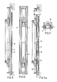
- FIGS. 11 and 11a show a further shield construction according to the invention.
- the furnace chamber with the associated heating or chamber walls is indicated by 1.
- the coke oven door is, e.g. described in the German patent application P 33 27 337.5, consisting of a door body, with a power transmission unit and a sealing unit.
- the power transmission unit runs as a hollow profile along the door frame and is connected to the door frame at least via a locking device.
- the locking device is designed as a spring lock. These include locking hooks on the door frame 7 and pivotable locking bars on the door body, which act on the door body 7 via springs or power pistons.
- the sealing unit has a sealing plate 5, which is pressed against the door frame on the circumference of the door frame by means of many evenly distributed and spring-mounted screws 4.
- 5a denotes a cover that serves for insulation.
- the sealing plate 5 can be designed as a hollow profile, the hollow profile being filled with insulating compound 5b.
- the sealing plate can be provided with a one-sided bulge according to Figures 1 and 7 to the outside.
- angle irons are attached distributed over the height, of which angle irons 15 are screwed with screws 16 to further angle irons 14, which in turn are connected to a shaped profile 9 as an external protective shield.
- the connection between the shaped profile 9 and the angle iron 14 is made by hanging the shaped profile 9 with suitable hooks 9a on the angle iron 14.
- flanges or other profiles or screws can also be used.
- Another shape profile is attached to the shape profile 9 in mirror image as a protective shield by means of bolts 13 with spacers.
- FIGS. 1 and 2 the positions of the shaped profiles are shown at a greater distance from one another at 18, 19 in dashed form.
- Figures 4 and 5 the difference between the smaller and larger distance between the shaped profiles from each other is made clear.
- the shaped profiles of the inner protective shield 8 forming the wefts overlap, while the shaped profiles of the outer protective shield 9 abut one another with sufficient play for thermal expansion.
- the distance between the inner protective shield 8 and the sealing surface between the door body and the door frame 7 is 400 mm.
- the distance between the two protective shields is 120 mm. This corresponds to the usual stone plug depth.
- the ratio of the distance between the two protective shields 8 and 9 to the distance between the outer protective shield 9 and the sealing surface between the door body and the door frame 7 is between 1: 1 and 1: 1a, preferably between 1: 3 and 1 : 5.
- FIG. 3 shows a number of possible cross sections for the shaped profiles.
- the shaped profiles can be rolled in one piece and / or folded and / or bent, or can be composed of several parts. The parts can be screwed or welded. In the simplest case, the shaped profiles are designed as smooth sheets.
- the cross sections according to FIG. 3 are advantageous. While according to FIG. 1, the shaped profiles are laterally connected to one another in cross section and have bulges in the middle between the connection points, the reverse is true according to FIG. 3.1.
- the shaped profiles according to FIG. 3.1 have a small distance in the middle and the shaped profiles are connected to one another via the bolts 13, while they are at a greater distance from the outside of the chamber walls.
- the protective shields then again run parallel to each other on the outside.
- the protective shields can also be curved in the form of a circular arc towards the chamber walls or angularly bent outwards according to FIG. 3.6.
- the ends are first curved outwards in the form of a circular arc and then again inwards in a semi-circular manner, so that the ends are directed towards one another.
- Figures 3.1 to 3.4 also contain various middle bulges, which are triangular, semicircular or trapezoid-like on the outside.
- All protective shields according to Figure 3 can be used together. I.e. e.g. combine the shaped profile 8 of FIG. 3.1 with the shaped profile 9 according to FIG. 3.2. This preferably serves to increase the section modulus of the shield construction.
- FIGS. 6 and 7 show additional sealing plates 24 which are provided with elongated holes 25.
- only one row of sealing plates is provided between the two shaped profiles 8 and 9.
- several rows of sealing plates can also be arranged one behind the other between the shaped profiles 8 and 9, or can be distributed over a plurality of shaped profiles arranged one behind the other.
- the sealing plates 24 are as close as possible to the outer molded profile 9 in order to hinder the gas entry into the outer raw gas channel between the molded profile 9 and the door body and to relieve the sealing member 6.
- FIG. 6 shows the raised state of the shaped profiles in the left half.
- the sealing plate 24 has settled from the chamber wall 2 in the raised state or has been pressed inwards and downwards by a plunger 26. It protrudes below the shape profile.
- the protective shields and sealing plates 24 stand on the furnace sole and the sealing plate 24 has leaned against the chamber wall 2.
- the sealing plate movement is up to 60 mm compared to the shaped profiles 8 and 9.
- the gap between the shaped profiles 8 and 9 and the chamber wall 2 is in the exemplary embodiment, depending on the width of the coke oven chamber, up to 20 mm in size. For example, a 15 mm gap is provided for an average chamber width of 45 cm.
- FIG. 7 also shows the S-shaped shape of the sealing plate 24, the sealing plates abutting the outer molded profile 9 on the inside and a vertical gap for the gas passage remaining between the molded profile 8 and the sealing plates.
- the various sealing plates 24 of the three shots of multi-part protective shields shown in FIG. 5a are optionally connected to one another via joints which, when the door is placed in the furnace chamber, transmit the upward movement of the lowest sealing plates 24 to the sealing plates arranged above them.
- Hinges with two hinge joints can serve as joints, which ensure power transmission in the vertical direction and allow freedom of movement in the horizontal longitudinal direction of the furnace chamber.
- the shield construction according to FIGS. 8 to 10 differs from the shield construction according to FIGS. 1 to 7 in that a further shield 40 is provided instead of the angle iron 14, 15.
- the shield 40 is screwed to the sealing plate 5 and the shields 8 and 9.
- a large number of screws are provided, which are distributed over the length of the door structure.
- One of the screws or a pair of screws arranged at the same height is firmly seated, the other screws can yield in the longitudinal slots of thermal expansion by displacement. The screws are loose for this, but are secured against complete loosening, for example with lock nuts.
- the shield 40 is in the same way as the shields 8 and 9 with that resulting from the distance of the shields 8 and 9 from the door body Dimension and the dimension resulting from the bulge of the sealing plate 5.
- the sealing plate 5 can also be regarded as a shield. All shields 5, 8, 9 and 40 can advantageously be made from sheet pile material.
- a shaped profile 50 with a larger bulge of 150 mm is provided instead of the sealing plate 5.
- a shield 41 is provided, the legs of which extend exactly to the edges of the shaped profile 50 which are produced by the bulging.
- the shield 41 is laterally provided with a plurality of slots 42.
Abstract
Description
Die Erfindung bezieht sich auf eine Koksofentür für einen Horizontalkammer-Verkokungsofen mit einem gleichzeitig als Wärmeschutz dienenden, in die Ofenkammer hineinragenden, mit dem Türkörper verbundenen einteiligen oder mehrteiligen Schutzschild, über den die Ofenfüllung in einem bestimmten Abstand vom Türkörper gehalten wird, wobei der Türkörper während des Verkokungsvorganges mit mindestens einer Verriegelungseinrichtung gegen den Türrahmen des Ofens gedrückt wird. Derartige Koksofentüren sind unter anderem auch in der DE-OS 33 27 337.5 enthalten. Dieser Vorschlag ist auf eine neuartige Ausbildung des Türkörpers mit der dazugehörigen Dichtungseinrichtung gerichtet. Der neue Türkörper zeichnet sich insbesondere durch Leichtbauweise, Preisvorteile gegenüber herkömmlichen Türen und durch hohe, dauerhafte Dichtwirkung aus.Nach der DE-OS 33 27 337.5 ist der neue Türkörper teilweise mit konventionellen feuerfesten Türstopfen kombiniert.The invention relates to a coke oven door for a horizontal chamber coking oven with a one-piece or multi-part protective shield, which at the same time serves as heat protection and protrudes into the oven chamber and is connected to the door body, by means of which the oven filling is held at a certain distance from the door body, the door body during of the coking process is pressed against the door frame of the furnace with at least one locking device. Such coke oven doors are also included in DE-OS 33 27 337.5. This proposal is aimed at a novel design of the door body with the associated sealing device. The new door body is characterized in particular by its lightweight construction, price advantages compared to conventional doors and by its high, permanent sealing effect. According to DE-OS 33 27 337.5, the new door body is partially combined with conventional fire-resistant door plugs.
Aus der deutschen Patentschrift 23 83 63 ist darüber hinaus eine Tür für Koksöfen mit an der Rückwand angebrachten, verstellbarem Schutzschild bekannt, wobei der Schutzschild durch gelenkige Zwischenglieder mit der Rückseite der Tür verbunden ist und sich gegenüber der Tür bewegen kann. Dabei soll der durch gelenkige Zwischenglieder mit der Rückseite der Tür verbundene Schutzschild durch eine Stellvorrichtung von außen in seiner jeweiligen Stellung arretierbar sein. Nach der Darstellung der Ausführungsbeispiele dieser Patentschrift ist der Schutzschild als ebene, einteilige Platte mit rückwärtigen Versteifungsrippen ausgebildet.
Bei einer derartigen Koksofentür mit ebenen, sich über die Türhöhe erstreckender einteiliger Platte, hat sich gezeigt, daß bei metallischer Ausführung dieses Schutzschildes bislang nicht überwundene Schwierigkeiten auftreten. Besonders augenfällig ist die starke Verformung des einteiligen Schutzschildes. Infolge eines großen Temperaturgefälles der koksseitigen Schutzschildfläche gegenüber der Türkörperseitigen Schutzschildfläche kommt es zu einer sehr starken Krümmung.In such a coke oven door with a flat, one-piece plate extending over the door height, it has been shown that difficulties have not been overcome in the metallic design of this protective shield. The strong deformation of the one-piece protective shield is particularly striking. As a result of a large temperature gradient between the coke-side protective shield surface and the door body-side protective shield surface, there is a very strong curvature.
Zum Zeitpunkt der Anmeldung des deutschen Patentes 23 83 63 waren die gebräuchlichen Höhen von Koksöfen 1,5 bis 2 m. Bei solch geringen Törhöhen liegt die Gesamtverformung dess Schutzschildes möglicherweise noch im Toleranzbereich. Bei heute gebräuchlichen Koksofenhöhen von 4 m, 6 m und in Zukunft 8 m und mehr würde die Gesamtverformung des Schutzschildes entweder dazu führen, daß zwischen Ofensohle und Schutzschild und zwischen Schutzschild und Kammerwänden solche Öffnungen auftreten, daß Kohle im Übermaß zwischen Schutzschild und Türkörper dringen. Dieser Effekt würde bei trockener Kokskohle, insbesondere vorerhitzter Einsatzkohle, noch ganz wesentlich verstärkt.At the time of filing the
In neuerer Zeit ist der Gedanke eines metallischen Schutzschildes wieder aufgegriffen worden. Dabei sind zwei Lösungswege in Angriff genommen worden.In recent times, the idea of a metallic protective shield has been taken up again. Two approaches have been tackled.
Beispielhaft für den einen Lösungsweg ist die US-Patentschrift 40 86 145. Darin wird versucht, den Verwerfungen durch eine möglichst intensive Verbindung und Abstützung des Schutzschildes am Ofenkörper entgegenzuwirken. Intensiv heißt hier: Das Schutzschild wird über mindestens einen über die ganze Länge des Schutzschildes verlaufenden Steg mit dem Türkörper verbunden. In einer Ausführungsform sind beiderseits des Steges Stützstangen vorgesehen. In einer anderen Ausführungsform sind zwei im Abstand voneinander verlaufende Stege vorgesehen, die durch seitliche Rippen noch zusätzlich versteift sind.An example of one solution is US Pat. No. 40 86 145. It attempts to counteract the faults by connecting and supporting the protective shield on the furnace body as intensively as possible. Intensive means here: The protective shield is connected to the door body via at least one web running the entire length of the protective shield. In one embodiment, support rods are provided on both sides of the web. In another embodiment, two webs running at a distance from one another are provided, which are additionally reinforced by lateral ribs.
Dieser Lösungsweg hat jedoch vor allem wärmetechnische Nachteile, indem Berührungswärme durch die Stege, Rippen und Stützstangen in den Türkörper geleitet wird. Die damit verbundene Erwärmung des Türkörpers führt leicht zu unerwünschten Leckagen.However, this solution has above all thermal disadvantages, in that contact heat is conducted through the webs, ribs and support rods into the door body. The associated heating of the door body easily leads to undesirable leaks.
Beispielhaft für den anderen eingeschlagenen Lösungsweg ist die deutsche Offenlegungsschrift 31 05 703. Dort ist ein Schutzschild gezeigt, der schuppenartig aufgebaut ist, d.h. aus einer Vielzahl kleinerer, sich überlappender Einzelteile besteht. Jedes Einzelteil ist separat befestigt. Die kleineren Einzelteile unterliegen zwar einer prozentual insgesamt gleichen Wärmedehnung wie ein einteiliger Schutzschild. Das absolute Maß der Wärmedehnung jedes Einzelteiles ist jedoch wesentlich geringer als das eines einteiligen Schutzschildes. Durch Einzelaufhängung der verschiedenen Einzelteile und die überlappende Anordnung der Einzelteile wirkt sich die Wärmeverformung eines jeden Einzelteiles nicht übermäßig auf die übrigen Einzelteile aus. Die Gesamtwärmeverformung hält sich in tragbaren Grenzen.The German published patent application 31 05 703 is an example of the other chosen approach. There, a protective shield is shown, which is constructed like a scale, i.e. consists of a large number of smaller, overlapping individual parts. Each item is attached separately. The smaller individual parts are subject to the same overall thermal expansion as a one-piece protective shield. The absolute degree of thermal expansion of each individual part is, however, much lower than that of a one-piece protective shield. Due to the individual suspension of the various individual parts and the overlapping arrangement of the individual parts, the thermal deformation of each individual part does not have an excessive effect on the other individual parts. The total heat deformation is within acceptable limits.
Nach einem neueren Vorschlag P 34 40 311.6 wird unter Beibehaltung eines einteiligen Schutzschildes ein anderer Weg begangen bzw. unter Verwendung eines mehrteiligen Schutzschildes nachteilige Wärmebelastungen vermieden. Dabei wird von der Überlegung ausgegangen: Betriebsschwierigkeiten können sich im Rohgaskanal zwischen Türkörper und Schutzschild einstellen, das wird darauf zurückgeführt, daß der Rohgaskanal bei derartigen Türen total erweitert ist und der sich dann einstellende Gasdruck je nach gefahrenem Vorlagendruck an der Koksofenbatterie mehr oder weniger schon nach kurzer Garungsdauer gemittelt über die Türhöhe von positiven auf negative Werte übergeht, d.h. aus ursprünglichem Überdruck entsteht dann Unterdruck. Dadurch entsteht Saugung. Bei nicht genügend dichten Koksofentüren führt diese Erscheinung zwangsläufig zum Einzug von atmosphärischer Luft zwischen dem Kammerrahmen und dem Türkörper. Die Luft dringt in den Rohgaskanal und verursacht dort unter anderem folgende Störungen: Durch die Aggressivität des Sauerstoffs kann eine schleichende Zerstörung am heißen Kopfmauerwerk der Ofenkammer eintreten; bei starken Undichtigkeiten kann an der Koksofentür das metallische Schutzschild mit seinen Befestigungen am Türkörper zum Schmelzen bzw. zur Zerstörung gebracht werden. Der Effekt wäre vergleichbar einer Brennschweißung.According to a more recent proposal P 34 40 311.6, another route is followed while maintaining a one-piece protective shield, or disadvantageous thermal loads are avoided using a multi-part protective shield. This is based on the consideration: Operating difficulties can arise in the raw gas duct between the door body and the protective shield, which is attributed to the fact that the raw gas duct is completely expanded in such doors and the gas pressure that then arises more or less depending on the original pressure driven on the coke oven battery short cooking time averaged over the door height changes from positive to negative values, ie negative pressure then arises from the original overpressure. This creates suction. If the coke oven doors are not sufficiently tight, this phenomenon inevitably leads to the intake of atmospheric air between the chamber frame and the door body. The air penetrates into the raw gas duct and causes, among other things, the following disturbances: The aggressiveness of the oxygen can result in a gradual destruction on the hot brickwork of the furnace chamber; In the event of severe leaks, the metallic protective shield with its fastenings on the door body can be melted or destroyed on the coke oven door. The effect would be comparable to flame welding.
Es waren auch Betriebsschwierigkeiten aus vorhandenen Temperaturgefällen gesehen. Dabei wird davon ausgegangen, daß die sich einstellenden Rohgastemperaturen im total erweiterten Rohgaskanal über die Abstände sowohl zwischen Schutzschild und Türkörper als auch zwischen den Kammerwänden bei ca. 500 bis 700°C je nach Garungszustand und Fahrweise des Koksofens liegen.Operating difficulties from existing temperature gradients were also seen. It is assumed that the resulting raw gas temperatures in the totally expanded raw gas channel over the distances between the protective shield and the door body and between the chamber walls are around 500 to 700 ° C, depending on the cooking condition and driving style of the coke oven.
Bei Kokstemperaturen von etwa 1100°C findet folglich ein Temperatursprung vom Schutzschild zum Rohgaskanal von ca. 400 bis 600°C statt. Diese Erscheinung führt zwangsläufig zu einer Dehnungsbeeinflußung bzw. zu unzulässigen Spannungen zwischen dem relativ kaltem Mauerwerk im Bereich des Rohgaskanales und dem realtiv heißen Kohle-berührten Mauerwerk bzw.relativ kalten Ofenrahmen. Daraus sind nicht kalkulierbare Wandschäden im Bereich des Kopfmauerwerkes zu erwarten. Ferner steigt die Gasdurchlässigkeit im Steinmaterial wegen der niedrigen Wandtemperaturen erheblich an, wobei sich die Oberflächenstruktur des Steinmaterials zunehmend mit der Laufzeit des Koksofens negativ verändert und zu Abplatzungen und Rissen neigt.At coke temperatures of around 1100 ° C, there is a temperature jump from the protective shield to the raw gas duct of around 400 to 600 ° C. This phenomenon inevitably leads to an influence on the expansion or to inadmissible tensions between the relatively cold masonry in the area of the raw gas duct and the real hot masonry in contact with coal or relatively cold furnace frame. Unpredictable wall damage in the area of the head masonry is to be expected from this. Furthermore, the gas permeability in the stone material increases considerably because of the low wall temperatures, the surface structure of the stone material increasingly changing negatively with the running time of the coke oven and tending to flake and crack.
Der ältere Vorschlag geht ferner davon aus, daß bei einem nicht mit Kokskohle gefüllten Koksofen oder bei einem überstehenden Koksofen (das Koksdrücken hat sich verzögert) der eingesetzte Schutzschild sich in kurzer Zeit so stark aufheizt, daß erhöhte Wärmestrahlung über den Schutzschild ungehindert zowohl auf den Türkörper als auch auf den Kammerrahmen einwirkt. Die Wärmeeinwirkung führt zu unkontrollierten Verformungen zum einen am konventionell gegossenen Türkörper (verursacht dadurch Türleckagen) zum anderen am Kammerrahmen. Am Kammerrahmen legt sich aufgrund der vermehrt auftretenden Kammerrahmenbiegung die Rahmenfuge zwischen Mauerwerk und Kammerrahmen frei. Es entsteht eine sogenannte Rahmenfugenleckage.The older proposal also assumes that in a coke oven that is not filled with coking coal or in a coke oven that protrudes (coke pressing has been delayed), the protective shield used heats up to such an extent in a short time that increased heat radiation via the protective shield unhindered both on the door body as well as acting on the chamber frame. The effect of heat leads to uncontrolled deformation on the one hand on the conventionally cast door body (thereby causing door leakage) and on the other on the chamber frame. Due to the increasing bending of the chamber frame, the frame joint between the masonry and the chamber frame is exposed on the chamber frame. A so-called frame joint leakage occurs.
Schließlich berücksichtigt der ältere Vorschlag, daß bei den üblichen Koksofentemperaturen der eingangs erläuterte Schutzschild über die Koksofenhöhe durchlaufend aufgrund seiner Geometrie als ebene einteilige Fläche zu starken Verwerfungen neigt. Das verursacht die bereits erläuterte Gefahr, daß beim Einsetzen oder Abziehen einer Koksofentür der Schutzchild sich an den Ofenwänden verklammert und abgerissen wird. Die Folgen sind auch Schäden an den Ofenwänden. Ferner vergrößern die auftretenden Verwerfungen des Schildes die Öffnungsbreite der beiden Spalte zwischen Schild und Koksofenwänden. Damit steigt der nicht erwünschte Kohleanfall im Rohgaskanal. Bei niedrigen Wassergehalten (kleiner 10 Gewichts-% H₂O) der Einsatzkohlenmischung ist der Kohlenanfall im erweiterten Rohgaskanal besonders groß. Dort führt die Kohle wegen der niedrigen Kopftemperaturen zu Nachteilen der unkontrollierten Kondensatbildung im Bereich der Türdichtung bzw. bildet einen Halbkoksstopfen unterschiedlicher Höhe, der nach jeder Ofenfahrt vom Bedienungspersonal manuell und zeitaufwendig entfernt werden muß.Finally, the older proposal takes into account the fact that, at the usual coke oven temperatures, the protective shield explained at the beginning tends to warp continuously over the height of the coke oven due to its geometry as a flat, one-piece surface. This causes the already explained risk that when a coke oven door is inserted or removed, the protective shield will cling to the oven walls and be torn off. The consequences are also damage to the furnace walls. Furthermore, the distortion of the shield that occurs increases the opening width of the two gaps between the shield and the coke oven walls. This increases the amount of unwanted coal in the raw gas channel. With low water contents (less than 10% by weight H₂O) of the input coal mixture, the amount of coal produced in the expanded raw gas channel is particularly large. There the coal leads to disadvantages of the uncontrolled formation of condensate in the area of the door seal due to the low head temperatures or forms a semi-coke plug of different heights, which has to be removed manually and time-consuming by the operating personnel after each furnace run.
Nach dem älteren Vorschlag werden alle diese Schwierigkeiten entweder unter Beibehaltung eines einteiligen oder unter Verwendung eines mehrteiligen sich über die Türhöhe erstreckenden Schutzschildes vermieden, indem zwischen dem Schutzschild und dem Türkörper mindestens noch ein weiterer ein- oder mehrteiliger Schild angeordnet ist.According to the older proposal, all of these difficulties are either avoided while maintaining a one-part or using a multi-part protective shield extending over the door height by arranging at least one further one-part or multi-part shield between the protective shield and the door body.
Durch den einen zusätzlichen Schild entstehen zwei Rohgaskanäle, die als innerer, koksseitiger Rohgaskanal und als äußerer, türkörperseitiger Rohgaskanal bezeichnet werden können. Bei mehreren zusätzlichen Schilden entstehen entsprechend mehr Rohgaskanäle.The one additional shield creates two raw gas channels, which can be called the inner, coke-side raw gas channel and the outer, door body-side raw gas channel. With several additional shields, more raw gas channels are created.
Mit Hilfe des inneren und äußeren Rohgaskanals kann die Rohgasabzugsmenge in der Art gesteuert werden bzw. vergleichmäßigt werden, daß der Rohgasdruck an der Dichtfläche zwischen Koksofentür und Kammerrahmen im meßbaren positiven Bereich optimiert wird.With the help of the inner and outer raw gas channel, the raw gas discharge quantity can be controlled or equalized in such a way that the raw gas pressure on the sealing surface between the coke oven door and the chamber frame is optimized in the measurable positive range.
Die Wärmestrahlung des Türkörpers nach außen verringert sich, indem der dem Türkörper zugewandte Schutzschild als Ekran wirkt. Wahlweise sind zwischen dem koksseitigen Schutzschild und dem Türkörper zusätzlich noch weitere Schutzschilde (Ekrane) angeordnet. Nach dem älteren Vorschlag sind die die Schutzschilde mittels Abstandhalter an dem Türkörper befestigt. Der Hohlraum zwischen dem Türkörper und dem Schutzschild, der dem Türkörper am nächsten ist, wird lediglich als Gaskanal genutzt.The heat radiation of the door body to the outside is reduced by the protective shield facing the door body acting as an crane. Optionally, additional protective shields (ecranes) are arranged between the coke-side protective shield and the door body. According to the older proposal, the protective shields are attached to the door body by means of spacers. The cavity between the door body and the protective shield that is closest to the door body is only used as a gas channel.
Der Erfindung liegt die Aufgabe zugrunde, die mit der P 34 40 311 vorgeschlagene Ekranisierung fortzubilden. das wird nach der Erfindung dadurch erreicht, daß anstelle der Abstandhalter ein weiterer Schutzschild verwendet wird. Der weitere Schutzschild erhöht den Ekranisierungseffekt. Überraschenderweise teilt der weitere Schutzschild dem Türkörper keine nennenswerte Wärmeverformung mit, sondern bewirkt er eine Formstabilisierung.The invention is based, to develop the proposed with the P 34 40 311 ecranization the task. this is achieved according to the invention in that a further protective shield is used instead of the spacers. The further protective shield increases the ecranization effect. Surprisingly, the additional protective shield does not notify the door body of any appreciable heat deformation, but rather stabilizes the shape.
Der Türstopfen stellt nunmehr in seiner Gesamtkonzeption ein reines Schildesign dar,und zwar im Prinzip bestehend aus Dichtungsschild (aus einem Stück als Ekran wirkend) und z.B. aus Formstabilitätsgründen aus einem aus einem Stück gefertigten Doppelschild. Die Schilde sind untereinander lose miteinander verbunden, um z.B. den unterschiedlichen Temperaturlagen an diesen Teilen hinsichtlich Dehnungen Rechnung zu tragen.The overall design of the door stopper now represents a pure shield design, in principle consisting of a sealing shield (acting as a crane as a single piece) and, for example, for dimensional stability reasons, of a double shield made of one piece. The shields are loosely connected to one another, for example to take account of the different temperature levels on these parts with regard to expansion.
Durch diese Art der Türkonzeption im Schilddesign wird erreicht:
- daß durch die Bildung mehrerer Gesamtspannungskanäle die Rohgasabzugsmengen in der Art gesteuert bzw. vergleichmäßigt werden, daß die freien Querschnitte der Gaskanäle über Tiefen und/oder Abmessungsveränderungen an den Bohlen selbst variierbar sind und dadurch die Strömungsverhältnisse der Rohgase und mithin der Rohgasdruck an der Dichtfläche zwischen Dichtungsorgan der Dichtungseinheit und Kammerrahmen im meßbaren positiven Bereich optimiert werden (die Anordnung mehrerer Formprofile ist möglich),
- daß die Wärmeabstrahlung des Türkörpers (Dichtungsschild) nach außen durch die Ekranwirkung der anderen Schilde verringert wird. Neben einer Einsparung an Isoliermaterial am Türkörper wird insbesondere durch den Ekranisierungseffekt bei überstehenden oder auch leerstehenden Koksöfen die sich einstellende hohe Wärmestrahlung auf den Türkörper und auf den Kammerrahmen ferngehalten. Dadurch kann die Innenisolierung der Dichtungsbohle nach außen verlegt werden. Zusätzlich wird durch eine Außenisolierung erreicht, daß je nach Gestaltung der Dichtungsschildtiefe (bis 150 mm möglich) der gesamte Gaskanalquerschnitt größer als der Gassamelraumquerschnitt ist (weitere Drucksenkung an der Dichtfläche). Eine Innenisolierung ist ebenfalls möglich,
- daß die Gaskanäle bezogen auf die Rohgasströmung untereinander freien Zugang haben (Anbringen von Schlitzen in den Schilden bzw. oben und unten offen),
- daß durch den Ekranisierungseffekt ein gleichmäßiger Temperaturabfall längs des Kopfmauerwerkes ausgehend von dem hohle- bzw. koksberührten Schild in Richtung Türkörperrücken erzielt wird,
- daß im Vergleich zu den bisher bekannten Türkonstruktionen durch die Formgebung der Schilde eine sehr viel höhere Formstabilität auch bei den üblichen hohen Koksofentemperaturen erzielt wird,
- daß die Wandstärken der Formprofile erheblich dünn ausführbar sind, so daß bei genügender Biegesteifigkeit das unmittelbare Befestigen an dem Türkörper sich überaus günstig auf eine weitere Gewichtsverminderung der gesamten Tür auswirkt,
- daß andere Geometrien der Schilde mit gleichen Eigenschaften ausführbar sind,
- daß wegen der symmetrischen Ausführung der Schilde die Schilde untereinander austauschbar sind,
- daß aufgrund der leichten Schildbauweise und der problemlosen Fertigung dieser Teile die Gesamtkonzeption sich kostengünstiger als die üblichen Bauweisen darstellt,
- daß die gesamte Tür neuerdings im Baukastenprinzip aufgebaut ist und eine wesentliche Kostenersparnis bei der Wartung bzw. Instandhaltung der Türen
- und daß das Schilddesign keine aufwendigen Schweißnähte mehr aufweist, sondern das auf dem Markt befindliche Verfahren der Bolzenschweißung als Kraftverbindung auf diese Konzeption hervorragend übertragbar ist (weitere Kostenersparnis).This type of door design in the sign design achieves:
- That the formation of several total voltage channels controls the raw gas discharge quantities in such a way that the free cross-sections of the gas channels can be varied over depths and / or dimensional changes on the screed itself and thereby the flow conditions of the raw gases and thus the raw gas pressure at the sealing surface between Sealing member of the Sealing unit and chamber frame are optimized in the measurable positive range (the arrangement of several shaped profiles is possible),
- That the heat radiation of the door body (sealing shield) to the outside is reduced by the ecrane effect of the other shields. In addition to saving on insulating material on the door body, the high heat radiation that occurs on the door body and on the chamber frame is kept away, in particular by the ecranization effect in the case of coke ovens that are protruding or empty. This means that the interior insulation of the sealing plank can be moved to the outside. In addition, external insulation ensures that, depending on the design of the sealing plate depth (up to 150 mm possible), the entire gas duct cross-section is larger than the gas-chamber space cross-section (further pressure reduction on the sealing surface). Internal insulation is also possible
- that the gas ducts have free access to each other in relation to the raw gas flow (making slots in the shields or open at the top and bottom),
that a uniform temperature drop along the head masonry is achieved by the ecranization effect, starting from the hollow or coke-touched shield in the direction of the back of the door body,
that, compared to the door constructions known to date, the shape of the shields results in a much higher dimensional stability even at the usual high coke oven temperatures,
that the wall thicknesses of the shaped profiles can be made considerably thin, so that with sufficient flexural rigidity, the direct fastening to the door body has an extremely favorable effect on a further weight reduction of the entire door,
that other shield geometries can be implemented with the same properties,
- Because of the symmetrical design of the shields, the shields are interchangeable,
- Because of the light shield construction and the problem-free manufacture of these parts, the overall concept is cheaper than the usual construction methods,
- That the entire door is recently built on a modular principle and a significant cost saving in the maintenance or servicing of the doors
- And that the shield design no longer has any expensive welds, but the method of stud welding on the market as a force connection is excellently transferable to this concept (further cost savings).
In den Figuren 1 bis 7 ist der ältere Vorschlag gezeigt. Die Figuren 8 bis 11 zeigen zwei Ausführungsbeispiele der Erfindung.
Figur 1 zeigt einen waagerechten Schnitt durch die in eine Kammeröffnung eingesetzte TürFigur 2 zeigt einen senkrechten Schnitt durch einen Teil der Tür.Figur 3 zeigt eine Reihe einsetzbarer Schutzschilde im Querschnitt.- Figur 4 und 5 zeigen im senkrechten Schnitt die Koksofentür mit verschiedenen Abständen zwischen den Schutzschilden.
Figur 5a zeigt eine Tür mit mehrteiligen Schutzschilden.Figur 6 zeigt ausschnittsweise die Schutzschilde mit Dichtblechen im angehobenen und gesenkten Zustand in der Koksofenkammer.Figur 7 zeigtwie Figur 1 einen waagerechten Schnitt durch eine andere Koksofentür.Figuren 8bis 10 zeigen eine erfindungsgemäße unmittelbar mit dem Türkörper verbundene Schildkonstruktion.
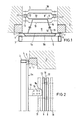
- Figure 1 shows a horizontal section through the door inserted into a chamber opening
- Figure 2 shows a vertical section through part of the door.
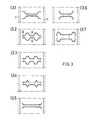
- FIG. 3 shows a number of protective shields that can be used in cross section.
- Figures 4 and 5 show in vertical section the coke oven door with different distances between the protective shields.
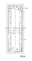
- Figure 5a shows a door with multi-part protective shields.
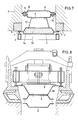
- FIG. 6 shows sections of the protective shields with sealing plates in the raised and lowered state in the coke oven chamber.
- Figure 7 shows like Figure 1 a horizontal section through another coke oven door.
- Figures 8 to 10 show a shield construction according to the invention directly connected to the door body.
Figuren 11 und 11a zeigen eine weitere erfindungsgemäße Schildkonstruktion. In den Figuren ist mit 1 die Ofenkammer mit den zugehörigen Heiz- oder Kammerwänden angedeutet. Um die senkrechte Öffnung der Ofenkammer 1 verläuft der Türrahmen 7, an dem das Dichtungsorgan 6 einer eingesetzten Koksofentür anliegt. Die Koksofentür besteht, wie z.B. in der d tschen Patentanmeldung P 33 27 337.5 beschrieben, aus einem Türkörper, mit einer Kraftübertragungseinheit und einer Dichtungseinheit. Die Kraftübertragungseinheit verläuft als Hohlprofil entlang dem Türrahmen und ist mindestens über eine Verriegelungseinrichtung mit dem Türrahmen verbunden. Die Verriegelungseinrichtung ist als Federverriegelung ausgebildet. Dazu gehören Verriegelungshaken am Türrahmen 7 und schwenkbare Verriegelungsbalken am Türkörper, die über Federn oder Kraftkolben auf den Türkörper 7 wirken. Die Dichtungseinheit besitzt eine Dichtungsplatte 5, die am Umfang des Türrahmens über viele gleichmäßig verteilte und federnd gelagerte Schrauben 4 gegen den Türrahmen gepreßt ist. Mit 5a ist eine Abdeckung bezeichnet, die der Isolierung dient. Zur Verbesserung der Wärmeisolierung nach außen hin kann die Dichtungsplatte 5 als Hohlprofil ausgebildet sein, wobei das Hohlprofil mit Isolierungsmass 5b ausgefüllt ist. Dabei kann die Dichtungsplatte mit einer einseitigen Ausbuchtung gemäß Figur 1 und 7 nach außen hin versehen sein. An der Innenseite der Dichtungsplatte 5 sind über der Höhe verteilt Winkeleisen befestigt, von denen Winkeleisen 15 über Schrauben 16 mit weiteren Winkeleisen 14 verschraubt sind, die wiederum mit einem Formprofil 9 als äußerem Schutzschild verbunden sind. Die Verbindung zwischen dem Formprofil 9 und dem Winkeleisen 14 wird durch Einhängen des Formprofils 9 mit geeigneten Haken 9a am Winkeleisen 14 hergestellt.FIGS. 11 and 11a show a further shield construction according to the invention. In the figures, the furnace chamber with the associated heating or chamber walls is indicated by 1. The
Anstelle der Winkeleisen 15 können auch Flansche oder andere Profile oder Schrauben verwendet werden. An dem Formprofil 9 ist spiegelbildlich ein weiteres Formprofil als Schutzschild über Bolzen 13 mit Abstandshaltern befestigt. In den Figuren 1 und 2 sind mit 18, 19 in gestrichelter Form die Positionen der Formprofile in größerem Abstand voneinander dargestellt. In den Figuren 4 und 5 ist ebenfalls der Unterschied zwischen geringerem und größerem Abstand der Formprofile voneinander deutlich gemacht.Instead of the
Bis auf die Ausführungen in Figur 4 und 5 gelten die Ausführungen sinngemäß auch für Schutzschilde, die aus mehreren Schüssen zusammengesetzt sind.Except for the explanations in FIGS. 4 and 5, the explanations also apply analogously to protective shields which are composed of several shots.
Nach Figur 5a sind mehrere Schüsse in einem Schutzschild übereinander angeordnet.According to FIG. 5a, several shots are arranged one above the other in a protective shield.
Dabei überlappen sich die die Schüsse bildenden Formprofile des inneren Schutzschildes 8, während die Formprofile des äußeren Schutzschildes 9 mit ausreichendem Spiel für eine Wärmedehnung aneinanderstoßen.The shaped profiles of the inner
Im Ausführungsbeispiel beträgt der Abstand des inneren Schutzschildes 8 von der Dichtfläche zwischen Türkörper und Türrahmen 7 400 mm. Der Abstand zwischen beiden Schutzschilden beträgt 120 mm. Das entspricht üblicher Steinstopfentiefe. In der Praxis stellt sich je nach Betriebsweise des Koksofens ein Verhältnis des Abstandes zwischen beiden Schutzschilden 8 und 9 zu dem Abstand des äußeren Schutzschildes 9 zur Dichtfläche zwischen Türkörper und Türrahmen 7 zwischen 1 :1 und 1 : 1a, vorzugsweise zwischen 1 : 3 und 1 : 5.In the exemplary embodiment, the distance between the inner
In der Figur 3 sind eine Reihe von möglichen Querschnitten für die Formprofile dargestellt. Die Formprofile können einteilig gewalzt und/oder gekantet und/oder gebogen sein, oder sich aus mehreren Teilen zusammensetzen. Die Teile können verschraubt oder verschweißt sein. Im einfachsten Fall sind die Formprofile als glatte Bleche ausgebildet. Vorteilhaft sind die Querschnitte nach Figur 3. Während gemäß Figur 1 die Formprofile im Querschnitt seitlich miteinander verbunden sind und zwischen den Verbindungsstellen in der Mitte Ausbuchtungen aufweisen, ist es gemäß Figur 3.1 umgekehrt. Dabei besitzen die Formprofile gemäß Figur 3.1 in der Mitte einen geringen Abstand und sind die Formprofile dort über die Bolzen 13 miteinander verbunden, während sie außen zu den Kammerwänden hin einen größeren Abstand aufweisen. Außen verlaufen die Schutzschilde dann wieder parallel zueinander. Die Schutzschilde können auch zu den Kammerwänden hin kreisbogenförmig oder gemäß Figur 3.6 eckig nach außen abgebogen sein.FIG. 3 shows a number of possible cross sections for the shaped profiles. The shaped profiles can be rolled in one piece and / or folded and / or bent, or can be composed of several parts. The parts can be screwed or welded. In the simplest case, the shaped profiles are designed as smooth sheets. The cross sections according to FIG. 3 are advantageous. While according to FIG. 1, the shaped profiles are laterally connected to one another in cross section and have bulges in the middle between the connection points, the reverse is true according to FIG. 3.1. The shaped profiles according to FIG. 3.1 have a small distance in the middle and the shaped profiles are connected to one another via the
Gemäß Figur 3.7 sind die Enden zunächst kreisbogenförmig nach außen und dann wiederum halbkreisförmig nach innen gebogen, so daß die Enden aufeinander zugerichtet sind. Die Figuren 3.1 bis 3.4 enthalten darüber hinaus verschiedene mittlere Ausbuchtungen, die nach außen dreieckförmig, halbkreisförmig oder trapezähnlich ausgebildet sind.According to FIG. 3.7, the ends are first curved outwards in the form of a circular arc and then again inwards in a semi-circular manner, so that the ends are directed towards one another. Figures 3.1 to 3.4 also contain various middle bulges, which are triangular, semicircular or trapezoid-like on the outside.
Alle Schutzschilde nach Figur 3 sind miteinander einsetzbar. D.h. es läßt sich z.B. das Formprofil 8 der Figur 3.1 mit dem Formprofil 9 nach Figur 3.2 kombinieren. Das dient vorzugsweise der Erhöhung des Widerstandsmomentes der Schildkonstruktion.All protective shields according to Figure 3 can be used together. I.e. e.g. combine the shaped
Aus den Figuren 6 und 7 sind schließlich zusätzliche Dichtbleche 24 ersichtlich, die mit Langlöchern 25 versehen sind. In den Ausführungsbeispielen ist zwischen den beiden Formprofilen 8 und 9 jeweils nur eine Reihe Dichtbleche vorgesehen. Statt der einen Reihe können jedoch auch mehrere Reihen von Dichtblechen hintereinander zwischen den Formprofilen 8 und 9 angeordnet sein, oder sich auf mehrere hintereinander angeordnete Formprofile verteilen.Finally, FIGS. 6 and 7 show
Die Dichtbleche 24 liegen möglichst eng an dem äußeren Formprofil 9, um den Gaseintritt in den äußeren Rohgaskanal zwischen Formprofil 9 und Türkörper zu behindern und das Dichtungsorgan 6 zu entlasten.The sealing
In der Figur 6 ist in der linken Hälfte der gehobene Zustand der Formprofile dargestellt. das Dichtblech 24 hat sich im gehobenen Zustand von der Kammerwand 2 abgesetzt bzw. ist von einem Stößel 26 nach innen und unten gedrückt worden. Unterhalb des Formprofils steht es über.FIG. 6 shows the raised state of the shaped profiles in the left half. the sealing
Im rechten, gesenkten Zustand der Formprofile stehen die Schutzschilde und Dichtbleche 24 auf der Ofensohle auf und hat sich das Dichtblech 24 an die Kammerwand 2 angelehnt. Die Dichtblechbewegung beträgt gegenüber den Formprofilen 8 und 9 bis zu 60 mm. Der Spalt zwischen den Formprofilen 8 und 9 und der Kammerwand 2 ist im Ausführungsbeispiel je nach Koksofenkammerbreite bis zu 20 mm groß. Z.B. sind bei einer mittleren Kammerbreite von 45 cm 15 mm Spalt vorgesehen.In the right, lowered state of the shaped profiles, the protective shields and sealing
Aus der Figur 7 ist im ünbrigen die S-förmige Gestalt des Dichtbleches 24 ersichtlich, wobei die Dichtbleche innen an dem äußeren Formprofil 9 anliegen und außen zwischen Formprofil 8 und den Dichtblechen ein senkrechter Spalt für den Gasdurchtritt verbleibt.FIG. 7 also shows the S-shaped shape of the sealing
Die verschiedenen Dichtbleche 24 der drei in Figur 5a dargestellten Schüsse von mehrteiligen Schutzschilden sind wahlweise miteinander über Gelenke verbunden, die beim Aufsetzen der Tür in der Ofenkammer die Aufwärtsbewegung der untersten Dichtbleche 24 auf die darüber angeordneten Dichtbleche übertragen. Entsprechendes gilt für die Abwärtsbewegung. D.h. sollte eine Dichtleiste beim Ausheben der Tür zögern, sich von der Kammerwand durch Abwärtsbewegung zu lösen, so wird dieser Widerstand vom Gewicht der anderen Dichtleisten überwunden. Als Gelenke können Schaniere mit zwei Schaniergelenken dienen, die in senkrechter Richtung eine Kraftübertragung sichern und in der horizontalen in Ofenkammerlängsrichtung Bewegungsfreiheit lassen.The
Die erfindungsgemäße Schildkonstruktion nach Figur 8 bis 10 unterscheidet sich von der Schildkonstruktion nach Figur 1 bis 7 dadurch, daß anstelle der Winkeleisen 14, 15 ein weiterer Schild 40 vorgesehen ist. Das Schild 40 ist mit der Dichtungsplatte 5 und den Schilden 8 und 9 verschraubt. Es sind eine Vielzahl von Schrauben vorgesehen, die über die Länge der Türkonstruktion verteilt sind. Eine der Schrauben oder ein auf fleicher Höhe angeordnetes Schraubenpaar sitzt fest, die anderen Schrauben können in Längsschlitzen der Wärmedehnung durch Verschiebung nachgeben. Die Schrauben sitzen dazu lose, sind aber gegen vollständiges Lösen z.B. durch Kontermuttern gesichert. Der Schild 40 ist in gleicher Weise wie die Schilde 8 und 9 mit dem sich aus dem Abstand der Schilde 8 und 9 zum Türkörper ergebendem Maß und dem sich aus der Auswölbung der Dichtungsplatte 5 ergebendem Maß gefertigt. Die Dichtungsplatte 5 kann gleichfalls als ein Schild angesehen werden. Alle Schilde 5, 8, 9 und 40 lassen sich vorteilhafterweise aus Spundbohlenmaterial fertigen.The shield construction according to FIGS. 8 to 10 differs from the shield construction according to FIGS. 1 to 7 in that a
Nach Figur 11 und 11a ist anstelle der Dichtungsplatte 5 ein Formprofil 50 mit größerer Auswölbung von 150 mm vorgesehen. Anstelle des Schildes 40 ist ein Schild 41 vorgesehen, dessen Schenkel genau auf die durch die Auswölbung entstandenen Kanten des Formprofiles 50 zulaufen. Außerdem ist das Schild 41 seitlich mit einer Vielzahl von Schlitzen 42 versehen.According to FIGS. 11 and 11a, a shaped
Claims (3)
Applications Claiming Priority (2)
| Application Number | Priority Date | Filing Date | Title |
|---|---|---|---|
| DE3540845 | 1985-11-18 | ||
| DE19853540845 DE3540845A1 (en) | 1985-11-18 | 1985-11-18 | COOKING OVEN FOR A HORIZONTAL CHAMBER COCING OVEN |
Publications (2)
| Publication Number | Publication Date |
|---|---|
| EP0223028A2 true EP0223028A2 (en) | 1987-05-27 |
| EP0223028A3 EP0223028A3 (en) | 1988-03-02 |
Family
ID=6286282
Family Applications (1)
| Application Number | Title | Priority Date | Filing Date |
|---|---|---|---|
| EP86113613A Withdrawn EP0223028A3 (en) | 1985-11-18 | 1986-10-02 | Door for a coke oven with horizontal chambers |
Country Status (3)
| Country | Link |
|---|---|
| EP (1) | EP0223028A3 (en) |
| JP (1) | JPS62119290A (en) |
| DE (1) | DE3540845A1 (en) |
Cited By (1)
| Publication number | Priority date | Publication date | Assignee | Title |
|---|---|---|---|---|
| EP0321640A1 (en) * | 1987-12-19 | 1989-06-28 | Ruhrkohle Aktiengesellschaft | Coke oven door with a shield construction |
Families Citing this family (1)
| Publication number | Priority date | Publication date | Assignee | Title |
|---|---|---|---|---|
| DE3743156A1 (en) * | 1987-08-03 | 1989-02-16 | Ruhrkohle Ag | COOKING OVEN DOOR WITH METAL PLATE |
Citations (3)
| Publication number | Priority date | Publication date | Assignee | Title |
|---|---|---|---|---|
| US4086145A (en) * | 1977-03-14 | 1978-04-25 | Jones & Laughlin Steel Corporation | Coke oven door lining |
| WO1985004180A1 (en) * | 1984-03-14 | 1985-09-26 | Firma Carl Still Gmbh & Co. Kg | Light construction stopper for coke oven doors |
| EP0163773A2 (en) * | 1984-01-05 | 1985-12-11 | Ruhrkohle Aktiengesellschaft | Door for a coke oven with horizontal chambers |
-
1985
- 1985-11-18 DE DE19853540845 patent/DE3540845A1/en not_active Ceased
-
1986
- 1986-10-02 EP EP86113613A patent/EP0223028A3/en not_active Withdrawn
- 1986-11-13 JP JP26881386A patent/JPS62119290A/en active Pending
Patent Citations (3)
| Publication number | Priority date | Publication date | Assignee | Title |
|---|---|---|---|---|
| US4086145A (en) * | 1977-03-14 | 1978-04-25 | Jones & Laughlin Steel Corporation | Coke oven door lining |
| EP0163773A2 (en) * | 1984-01-05 | 1985-12-11 | Ruhrkohle Aktiengesellschaft | Door for a coke oven with horizontal chambers |
| WO1985004180A1 (en) * | 1984-03-14 | 1985-09-26 | Firma Carl Still Gmbh & Co. Kg | Light construction stopper for coke oven doors |
Cited By (1)
| Publication number | Priority date | Publication date | Assignee | Title |
|---|---|---|---|---|
| EP0321640A1 (en) * | 1987-12-19 | 1989-06-28 | Ruhrkohle Aktiengesellschaft | Coke oven door with a shield construction |
Also Published As
| Publication number | Publication date |
|---|---|
| DE3540845A1 (en) | 1987-05-21 |
| EP0223028A3 (en) | 1988-03-02 |
| JPS62119290A (en) | 1987-05-30 |
Similar Documents
| Publication | Publication Date | Title |
|---|---|---|
| EP0028679A1 (en) | Coke oven door with a voluminous gas collecting space | |
| EP0166711B1 (en) | Construction element for a tile stove | |
| DE3105703C2 (en) | Coking plate composed of shields | |
| DE2948104C2 (en) | Electrolysis tank | |
| EP0223028A2 (en) | Door for a coke oven with horizontal chambers | |
| DE3739452C1 (en) | Coke oven door with ceramic shield structure | |
| EP0163773B1 (en) | Door for a coke oven with horizontal chambers | |
| DE3439860C2 (en) | ||
| DE3440311C2 (en) | ||
| DE3409224C2 (en) | ||
| EP0058320B1 (en) | Process for the coking of coal and coke oven for carrying out the process | |
| DE2908839C2 (en) | Device for sealing the chambers of coking ovens | |
| DE1526160B2 (en) | Wall construction for fireplaces | |
| DD202304A5 (en) | METHOD OF SEALING HORIZONTAL CHAMBER BOILING PAN AND COOKING OVEN WITH COOKING FUELS | |
| EP0154232B1 (en) | Coke oven door with a separate shield for heat protection | |
| DE2724982C3 (en) | Coke oven door stopper made of refractory bricks | |
| DE875340C (en) | Furnace head reinforcement with separate detachable door frame | |
| EP0084366B1 (en) | Coke oven chamber door | |
| DE8313165U1 (en) | Elastic coke oven door with multi-point locking | |
| EP0114183B1 (en) | Door for coke oven with horizontal chambers | |
| DE3123249C2 (en) | Plug connection for shield-shaped coking plate | |
| DE935548C (en) | Slag chamber lock for Siemens-Martin-OEfen | |
| DE4314630A1 (en) | Heat-insulating side wall for ovens or the like | |
| DE3123248A1 (en) | Tight coke oven door II | |
| DE3729400A1 (en) | Coke oven door stopper |
Legal Events
| Date | Code | Title | Description |
|---|---|---|---|
| PUAI | Public reference made under article 153(3) epc to a published international application that has entered the european phase |
Free format text: ORIGINAL CODE: 0009012 |
|
| AK | Designated contracting states |
Kind code of ref document: A2 Designated state(s): BE DE ES FR GB GR NL |
|
| PUAL | Search report despatched |
Free format text: ORIGINAL CODE: 0009013 |
|
| AK | Designated contracting states |
Kind code of ref document: A3 Designated state(s): BE DE ES FR GB GR NL |
|
| 17P | Request for examination filed |
Effective date: 19880120 |
|
| 17Q | First examination report despatched |
Effective date: 19890621 |
|
| STAA | Information on the status of an ep patent application or granted ep patent |
Free format text: STATUS: THE APPLICATION IS DEEMED TO BE WITHDRAWN |
|
| 18D | Application deemed to be withdrawn |
Effective date: 19900420 |
|
| RIN1 | Information on inventor provided before grant (corrected) |
Inventor name: BECKER, WOLFGANG, DR. |