EP0222918A1 - Übertragungssystem zur übertragung von dreidimensionalen fernsehbildern - Google Patents
Übertragungssystem zur übertragung von dreidimensionalen fernsehbildern Download PDFInfo
- Publication number
- EP0222918A1 EP0222918A1 EP86902906A EP86902906A EP0222918A1 EP 0222918 A1 EP0222918 A1 EP 0222918A1 EP 86902906 A EP86902906 A EP 86902906A EP 86902906 A EP86902906 A EP 86902906A EP 0222918 A1 EP0222918 A1 EP 0222918A1
- Authority
- EP
- European Patent Office
- Prior art keywords
- picture
- signal
- difference signal
- separated
- time
- Prior art date
- Legal status (The legal status is an assumption and is not a legal conclusion. Google has not performed a legal analysis and makes no representation as to the accuracy of the status listed.)
- Ceased
Links
Images


Classifications
-
- H—ELECTRICITY
- H04—ELECTRIC COMMUNICATION TECHNIQUE
- H04N—PICTORIAL COMMUNICATION, e.g. TELEVISION
- H04N7/00—Television systems
- H04N7/12—Systems in which the television signal is transmitted via one channel or a plurality of parallel channels, the bandwidth of each channel being less than the bandwidth of the television signal
- H04N7/122—Systems in which the television signal is transmitted via one channel or a plurality of parallel channels, the bandwidth of each channel being less than the bandwidth of the television signal involving expansion and subsequent compression of a signal segment, e.g. a frame, a line
-
- H—ELECTRICITY
- H04—ELECTRIC COMMUNICATION TECHNIQUE
- H04N—PICTORIAL COMMUNICATION, e.g. TELEVISION
- H04N19/00—Methods or arrangements for coding, decoding, compressing or decompressing digital video signals
- H04N19/50—Methods or arrangements for coding, decoding, compressing or decompressing digital video signals using predictive coding
- H04N19/597—Methods or arrangements for coding, decoding, compressing or decompressing digital video signals using predictive coding specially adapted for multi-view video sequence encoding
-
- H—ELECTRICITY
- H04—ELECTRIC COMMUNICATION TECHNIQUE
- H04N—PICTORIAL COMMUNICATION, e.g. TELEVISION
- H04N7/00—Television systems
- H04N7/08—Systems for the simultaneous or sequential transmission of more than one television signal, e.g. additional information signals, the signals occupying wholly or partially the same frequency band, e.g. by time division
- H04N7/0806—Systems for the simultaneous or sequential transmission of more than one television signal, e.g. additional information signals, the signals occupying wholly or partially the same frequency band, e.g. by time division the signals being two or more video signals
-
- H—ELECTRICITY
- H04—ELECTRIC COMMUNICATION TECHNIQUE
- H04N—PICTORIAL COMMUNICATION, e.g. TELEVISION
- H04N13/00—Stereoscopic video systems; Multi-view video systems; Details thereof
- H04N13/10—Processing, recording or transmission of stereoscopic or multi-view image signals
-
- H—ELECTRICITY
- H04—ELECTRIC COMMUNICATION TECHNIQUE
- H04N—PICTORIAL COMMUNICATION, e.g. TELEVISION
- H04N13/00—Stereoscopic video systems; Multi-view video systems; Details thereof
- H04N13/10—Processing, recording or transmission of stereoscopic or multi-view image signals
- H04N13/106—Processing image signals
- H04N13/111—Transformation of image signals corresponding to virtual viewpoints, e.g. spatial image interpolation
-
- H—ELECTRICITY
- H04—ELECTRIC COMMUNICATION TECHNIQUE
- H04N—PICTORIAL COMMUNICATION, e.g. TELEVISION
- H04N13/00—Stereoscopic video systems; Multi-view video systems; Details thereof
- H04N13/10—Processing, recording or transmission of stereoscopic or multi-view image signals
- H04N13/189—Recording image signals; Reproducing recorded image signals
-
- H—ELECTRICITY
- H04—ELECTRIC COMMUNICATION TECHNIQUE
- H04N—PICTORIAL COMMUNICATION, e.g. TELEVISION
- H04N13/00—Stereoscopic video systems; Multi-view video systems; Details thereof
- H04N13/20—Image signal generators
- H04N13/204—Image signal generators using stereoscopic image cameras
- H04N13/239—Image signal generators using stereoscopic image cameras using two two-dimensional [2D] image sensors having a relative position equal to or related to the interocular distance
-
- H—ELECTRICITY
- H04—ELECTRIC COMMUNICATION TECHNIQUE
- H04N—PICTORIAL COMMUNICATION, e.g. TELEVISION
- H04N13/00—Stereoscopic video systems; Multi-view video systems; Details thereof
- H04N13/30—Image reproducers
Definitions
- the present invention relates to a stereoscopic television picture transmission system in which a stereoscopic television signal having compressed frequency band is transmitted or recorded, and more particularly to a stereoscopic television picture transmission system for displaying a high definition television picture by performing subsampling with considering a time-frequency characteristic of visual parallax of human being in a depth direction of a picture.
- a difference signal that is, a parallax signal of right and left picture signals is compressed to be transmitted by utilizing a degree of correlation between the right and left pictures. That is, the parallax between the right and left pictures exists only in a near distance view (for instance, an object within 10 meters from the cameras) exists and does not exist in case of a long- distance view, so that the difference signal is produced only when parallax exists. Therefore, it is considered to compress and transmit the difference signal by effecting the time-axis compression of a time interval in which no parallax exists.
- the difference signal originally includes many high frequency components of 1-2MHz so that when the difference signal is compressed in the manner described above, the limitation of the differential signal band aversely affects the generation of a quality stereoscopic picture.
- one of the objects of the present invention is to provide a stereoscopic television picture transmission system which substantially eliminates causes for degrading a quality of pictures and which compresses the stereoscopic picture signals into a conventional one channel television signal band, so that a high quality stereoscopic picture can be transmitted.
- Another object of the present invention is to provide a sterescopic television picture transmission system in which of stereoscopic pictures, a picture which moves in a direction of depth (referred to as "a moving picture") and a picture which does not move in the direction of the depth (and which is referred to as "a still picture” including a picture which does not move in the direction of the depth even if it moves two- dimensionally) are subjected to different processings from the standpoint of visual characteristics so as to compress the frequency band occupied by the moving pictures, so that it becomes possible to transmit a higher frequency component of the difference signal, whose transmission is difficult when the difference signal is merely compressed and therefore a high definition stereoscopic picture can be displayed.
- a moving picture a picture which moves in a direction of depth
- a still picture including a picture which does not move in the direction of the depth even if it moves two- dimensionally
- the present invention utilized is the fact that when a time-frequency characteristic of parallax in characteristics of visual perception in depth is considerably deteriorated as compared with a still picture when the frequency is increased; that is, in case of a moving picture, so that the depth perception by parallax is almost eliminated. That is, from the standpoint of visual perception, there arises no problem even when the resolution in the direction of the depth of the moving picture in the difference signal is reduced to 1/2-1/6 of the resolution in the direction of the depth of the still picture.
- the difference signal for the moving picture is considerably compressed, while the difference signal for the still picture is less compressed, so that it becomes possible to transmit the higher frequency component of the difference signal, which has been hitherto difficult when the difference signal is merely compressed.
- a stereoscopic television picture transmission system is characterized by comprising:
- picture elements of at least a picture longer than one frame may be interpolated sequentially by a difference signal between adjacent frames of a plurality of successive frames.
- At least the separated difference signal may be subject to the interfield interpolation.
- the separated difference signal may be subject to the interfield interpolation.
- both of the difference signal and the one picture signal may be time-axis compressed and time-axis multiplexed to be transmitted.
- a stereoscopic television picture receiving apparatus is characterized by comprising:
- picture elements at least of a picture longer than one frame may be sequentially interpolated by a difference signal between adjacent frames of a plurality of succeeding frames.
- At least the separated difference signal may be subject to the interfield interpolation.
- the separated difference signal may be subject to interfield interpolation.
- a stereoscopic television picture transmission system is characterized by comprising:
- the interframe interpolation of the separated difference signal may be carried out.
- a motion in a predetermined number of fields in the separated difference signal may be judged in such a way that when a motion judgement result indicates a still picture, the separated difference picture is derived as it is, and when the motion judgement result indicates a motion picture, the separated difference signal is derived every time of the predetermined number of fields.
- Fig. 1 shows schematically on outline construction of a stereoscopic television system to which the present invention is applied.
- Output signals V L and V R corresponding to the images perceived by left and right eyes are derived from a left camera 2 and a right camera 4 and then are combined by a signal processing encoder 6 so that the combined signal is delivered to a transmission line or a VTR 8.
- a decoder 10 decodes the signal transmitted through the transmission line or from the VTR 8 to separate the output signal V' L from the output signal V' R so that a three dimensional picture is displayed on a CRT 12.
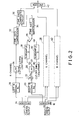
- Fig. 2 is a detailed block diagram showing an embodiment of the signal processing encoder 6.
- the signal processing circuit using R, G and B signals is embodied, but it is to be understood that the present invention is not limited to the above-described circuit and that it may be equally applied to any of the processing methods (l)-(3) described above.
- Reference numerals 28 and 30 denote sampling circuits for subsampling the output signal from the low-pass filter 26 in a manner described in detail hereinafter with reference to Figs. 4B and 4C.
- the input to the sampling circuits 28 and 30 and the output derived from the sampling circuits 28 and 30 are switched at every frame by analog switches 27 and 29 which are actuated in synchronism with each other so that the sampling circuit 28 subsamples an even-numbered frame (that is, 2m th frame), while the sampling circuit 30 subsamples an odd-numbered frame (that is (2m+l)th frame.
- Reference numerals 32 and 34 denote time-axis compression circuits for performing the time-axis compression of the outputs from the filter 24 and the switch 29, respectively, at different time-axis compression ratios.
- Reference numeral 36 is a time-axis composition circuit for combining the output from the compression circuits 32 and 34 in the direction of time axis.
- Reference numeral 38 denotes a processing circuit for a G signal and reference numeral 40 denotes a processing circuit for a B signal, both of which are arranged substantially similar to the circuits 18-36 for processing the R signal.
- the reason why only the R channel is shown in Fig. 2 is that the substantially similar processing circuits may be used for the G and B channels.
- Reference numeral 42 denotes an encoder for encoding the outputs from the time-axis composition circuits 37 for the R, G and B channels to form a stereoscopic picture signal.
- the stereoscopic picture signal in the first embodiment use the output signal (added with L) from the left camera as a reference signal.
- the frequency bands of the output signals from the left and right cameras and the frequency band of the output signal from the encoder 42 are all 6MHz.
- the left camera output derived from the low pass filter 24 is applied to the time-axis compression circuit 32 to accomplish the time-axis compression by 3/4 as shown in Fig. 3.
- a frequency band to be occupied by the difference signal is limited to 1/2 with respect to the left camera output as shown in Fig. 4A, so that the sampling number of the difference signal which has passed through the low-pass filter 26 becomes one half.
- Sub-Nyquist sampling in which the difference signal from the low-pass filter 26 is alternately applied through the switch 27 to the subsampling circuits 28 and 30 for each frame and then one difference signal is subtracted so that the subsampling outputs are derived for even-numbered and odd-numbered frames, respectively, as shown in Figs. 4B and 4C.
- Sample information obtained by subtracting 1/4 sampling points from all of the sampling points is derived by the switch 29.
- the difference signal at every frame obtained by the subsampling in the manner described above is applied to the time-axis compression circuit 34 so that the difference signal is time-axis compressed to form a signal whose frequency band is 6MHz.
- the signal thus obtained and the time-axis compressed output with respect to the left camera are combined in the time-axis direction, so that the combined signal as shown in Fig. 3 is obtained.
- the time-axis combined signals are obtained in both the G and B channels. These signals are applied to the encoder 42 and then converted into coded signals which in turn are transmitted through the transmission line or are recorded by a VTR.
- Each of the subsampling circuits 28 and 30 described above may be a circuit, for instance, CX20096 manufactured by Sony which performs sample holding at the timing of a sample hold pulse generated in response to the frame pulse.
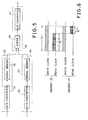
- the time-axis compression circuit 32 and the time-axis composition circuit 36 may be arranged as shown in Fig. 5, for instance. That is, the time-axis compression circuits 32 and 34 for the left camera signal delivered from the low-pass filter 24 comprise A/D converters 31 and 33, and serial memories 35 and 37 for storing therein the digital output derived from the A/D converters 31 and 33, respectively.
- serial memories 35 and 37 when the digital signals derived from the A/D converters 32 and 33 are stored in response to a write-in clock of f (Hz), read-out clocks are determined to be f x a/(a-1)(Hz) and f x a(Hz), so that the stored signals are compressed by (1 -(1/ ⁇ )] x H and (1/a) x H and then read out, respectively, as shown in Fig. 6.
- the time-axis composition circuit 36 comprises a digital adder 39 and a D/A converter 41.
- the output signals derived from the memories 35 and 37 are added to each other in the digital adder 39.
- the output from the digital adder 39 is in turn converted into an analog output by the D/A converter 41 (for instance, CX20051A manufactured by Sony) to obtain a time-axis composite output.
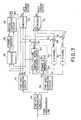
- Fig. 7 is a block diagram showing an embodiment of the whole arrangement of the decoder.
- Reference numeral 50 designates a time-axis separation circuit which receives the stereoscopic picture signal from the transmission line or the VTR to deliver a reproduced left camera signal and a difference signal in the manner described above with reference to Fig. 3.
- Reference numerals 52 and 54 are time-axis expansion circuits which receive the reproduced left camera signal and the reproduced difference signal to expand the signals in the time-axis direction so as to derive expanded signals R L , G L and B L and Rp, G A and B A , each having a time interval equal to 1H.
- Reference numeral 56 denotes an encoder which receives the left camera signals R L , G L and B L from the time-axis expansion circuit 52 to generate a luminance signal Y and 58, a frame memory for storing therein the luminance signal Y for a time period of one frame.
- Reference numeral 60 denotes a motion judgement circuit which receives the luminance signal Y D delayed by one frame and derived from the frame memory 58 and the present luminance signal Y to detect a motion between the frames so as to form interpolation control pulses R IC , G IC and B IC .
- Reference numeral 62 designates a circuit which receives the difference signal R 6 from the time-axis expansion circuit 54 and the signal R ⁇ D which is derived from a frame memory 64 which delays the difference signal R A by one frame and responds to an interpolation control signal R IC derived from the motion judgement circuit 60 to form a difference signal R ⁇ I in which the picture elements in the still region are interpolated (The present embodiment is described only in conjunction with the R channel, but the circuits for the G and B channels are substantially similar in construction to the circuit for the R channel).
- Reference numerals 66, 68 and 70 designate adders for adding the interpolated difference signals R ⁇ I , G ⁇ I and B AI from the respective R, G and B channels to the signals R L , G L and B L from the time-axis expansion circuit 52 to form right camera signals R R , G R and BR.
- Reference numerals 72 and 74 denote encoders for combining the left camera signals R L , G L and B L with the right camera signals R R , G R and B R to reproduce the left and right camera outputs V L and V R , respectively.
- the transmitted stereoscopic picture signal is separated into the left camera signal and the difference signal by the time-axis separation circuit 50 and then the respective output signals from the circuit 50 are applied to the time-axis expansion circuits 52 and 54, in which the time-axis expansion of the signals in the respective R, G and B channels are carried out, so that the left camera signal R L , G L and B L and the difference signals R ⁇ , Gp and BA are reproduced.
- the difference signals R ⁇ , G ⁇ and B ⁇ have been subjected to the sub-Nyquist sampling on the encoder side as described above, so that in the still picture portion interpolation circuit 62, the difference signal R A is interpolated with the preceding frame signal obtained by delaying the difference signal by one frame by the frame memory 64 to reproduce again the signal of 3MHz. That is to say, the sample output shown in Fig. 4B and the sample output shown in Fig. 4C are interpolated with each other as shown in Fig. 4E to obtain the interpolation outputs R ⁇ I, G AI and B ⁇ I .
- the moving picture portion is not interpolated with the preceding frame, and the present difference signal itself is delivered as shown in Fig. 4F. Therefore, in this case a frequency band occupied by the difference signal remains unchanged and is 1.5MHz.
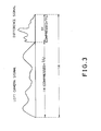
- Fig. 8 illustrates how the depth perception sensitivity drops when a picture exhibiting a wave-like sense of depth is displayed by a random dot stereo pattern and the amplitude of the wave (that is, the amplitude of the wave in the depth direction) is varied by a frequency plotted along the abscissa.
- the random dot stereo pattern will be explained.
- a random dot having a parallax when observed by the respective eyes, a part of the random dots seems in relief or depressed so that the viewed image has a three-dimensional appearance.
- an amount of parallax is modulated by a low frequency to produce a motion picture of concave and convex moving in the depth direction, so that the depth perception sensitivity is measured.
- the depth perception sensitivity drops by more than 30 dB at a frequency of about 3Hz. Even when the displayed picture is smoothly varied in the form of a sinusoidal waveform, the depth perception sensitivity drops by more than 30 dB at a frequency of about 5Hz.
- the signals R L , G L and B L delivered from the time-axis expansion circuit 52 are applied to the encoder 56 to form the luminance signal Y, which in turn is stored in the frame memory 58.
- the motion judgement circuit 60 obtains a difference between the present luminance signal Y delivered from the encoder 56 and the delayed luminance signal Y D in the preceding frame delivered from the frame memory 58.
- the motion of the picture is judged by detecting whether or not the difference between the luminance signals thus obtained exceeds a predetermined threshold value.
- each frame memory suffices to have 5 bits at the most. That is, the difference between the left and right pictures is caused only by the parallax and the correlation between the both picture elements is high, so that it may be considered as a kind of a one-dimentional DPCM system. In this case, five bits suffices to provide the high quality picture which can satisfy even an expert in the art.
- the remaining memory is used to detect a motion and suffices to have the capacity of the order of five bits.
- Fig. 9 is a block diagram showing detailed embodiments of the time-axis separation circuit 50 and the time-axis expansion circuits 52 and 54.
- the time-axis separation circuit 50 comprises an A/D converter 80 and a digital switch 32.
- the stereoscopic picture signal received through the transmission line is converted by the converter 80 into a digital signal which in turn is switched by the digital switch 32 at a timing of a control signal shown in Fig. 10, so that the left camera signal and the difference signal are separated from each other.
- the left camera signal and the difference signal thus obtained are applied to the time-axis expansion circuits 52 and 54, respectively, which are formed by serial memories, and are written therein at a timing of write clocks having a frequency of fx ⁇ / ( ⁇ -1) (Hz) and a frequency of fx ⁇ (Hz) as shown in Fig. ll.
- the data stored in the serial memories 52 and 54 are read out at the same frequency f(Hz), so that the left camera signal R L and the difference signal R ⁇ which are expanded in the direction of the time axis are obtained.
- the remaining G and B channels have similar arrangements.
- Fig. 12 shows a detailed embodiment of the motion judgement circuit 60 and the interpolation circuit 62 for interpolating picture elements in a still picture region.
- the motion judgement frame memory 58 is formed by a four-bit memory
- the difference signal frame memory 64 is formed by a six-bit memory for each of R, G and B. The following explanation will be made only in conjunction with the R channel hereinafter, but the G and B channels may be arranged in the same manner.
- the luminance signal Y delivered from the encoder 56 is converted by an A/D converter 84 into a digital luminance signal consisting of four bits which in turn are stored frame by frame into the frame memory 58 (for instance, MN7400 manufactured by Matsushita). It is sufficient that the memory 58 stores motion data and therefore it is not necessary that the memory 58 has a high resolution, and hence it is sufficient that the memory 58 is a four-bit memory.
- the luminance signal YD from the frame memory 53 and the digital luminance signal from the A/D converter 84 are applied to a digital difference circuit 86 so as to obtain a difference in luminance signal between the present frame and the preceding frame.
- the difference signal R ⁇ from the time-axis expansion circuit 54 is applied to an A/D converter 92 to be converted into a digital difference signal consisting of 6 bits which in turn is applied to the six-bit frame memory 64 (for instance, MN7400x2) and to a six-bit digital switch 62 as the still picture region interpolation circuit 62.
- the digital switch 62 is switched to the motion picture position M or to the still picture position S.
- the difference signal of the present frame that is, the output from the converter 92 is derived as it is from the switch 62.
- the difference signal R ⁇ D from the frame memory 64 is derived from the digital switch 62 to accomplish the interpolation.
- the difference signal derived from the digital switch 62 is applied to a D/A converter 94 (for instance, CX20051A manufactured by Sony) to be converted into an analog signal which in turn is applied as the difference signal R AI to the adder 66.
- a difference signal of a motion picture moving in the depth direction is stored every 8 fields (about 8Hz) and in case of the transmission of the picture signal, the difference signal is thin out, as illustrated in Figs. 4B and 4C, so as to reduce the frequency band.
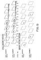
- picture elements of 8 fields are stored and, every 8 fields, the difference signal of the picture moving in the depth direction is reproduced. Then, the two-dimensional resolution of the picture moving in the depth direction can be increased as will be described in detail with reference to Fig. 13.
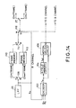
- Fig. 14 shows an embodiment of the encoder used in the second embodiment.
- the circuit as shown in Fig. '14 is inserted between the low-pass filter 26 and the analog switch 27 shown in Fig. 2.
- the difference signals R ⁇ , G ⁇ and B ⁇ derived from the respective low-pass filters 26 for the R, G and B channels are applied to an encoder 102, so that the difference signal Y ⁇ of the luminance signal is obtained.
- the difference signal Y ⁇ is applied to an eight-field memory 104 to obtain an output Y ⁇ D delayed by eight fields, which in turn is applied, together with the present difference signal Yp, to a judgement circuit 106 which is substantially similar to that shown in Fig. 12, to compare the both signals Y ⁇ D and Yp, so that a motion is detected depending upon whether the difference output between the signals Y OD and Y ⁇ is higher or lower than a predetermined threshold value.
- the difference signal R ⁇ , G ⁇ and B ⁇ derived from the respective low-pass filters 26 for the R, G and B channels are applied to an analog switch 108 which switches every frame so that an even-number frame is stored in a frame memory 110, while an odd-number frame is stored in a frame memory 112.
- an analog switch 108 which switches every frame so that an even-number frame is stored in a frame memory 110, while an odd-number frame is stored in a frame memory 112.
- each of the frame memories 110, and 112 stores one frame.
- the outputs from the frame memories 110 and 112 are alternately derived through an analog switch 114 which is switched in synchronism with the switch 108.
- the output from the switch 114 is applied to the switch 27 shown in Fig. 2 through an analog switch 116 which is actuated in response to the output signal from the motion judgement circuit 106.
- An M side contact of the switch 116 indicates a motion picture contact M and an S side contact of the switch 116 indicates a still picture contact.
- the switch 116 when the switch 116 is on the contact S side, the output from the low-pass filter 26 is directly applied to the switch 27.
- its motion information is judged every 8 fields and the output from the frame memory 110 or l12 is subjected to the sub-Nyquist sampling in the subsampling circuit 28 or 30.
- motion information is subjected to the subsampling every 8 fields.
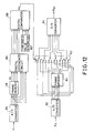
- the decoder used in the second embodiment may be arranged as shown in Fig. 15.
- the same reference numerals are used to designate similar parts in both Figs. 7 and 15 and the explanation of the parts will be omitted.
- an encoder 120 receives the difference signal R ⁇ , G A and B ⁇ from the time-axis expansion circuit 54 to form the difference signal Y A of the luminance signal.
- the difference signal is then applied to an eight-field memory 122 to obtain a difference signal Y AD delayed by eight fields, which in turn is applied to the motion judgement circuit 60.
- the motion judgement circuit 60 detects whether or not motion exists every 8 fields and delivers the judgement outputs Rc, Gc and Bc.
- an eight-field memory is used as the field memory 122, so that in order to reduce its storage capacity, the difference signals R ⁇ , G A and BA are stored.
- the difference signal R ⁇ , Gp and B ⁇ derived from the time-axis expansion circuit 54 are applied to the respective frame memories 64 for respective channels.
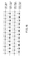
- the frame memory 64 has a storage capacity sufficient to store all picture elements of one frame which is sub-Nyquist- sampled. Irrespective of a still picture portion or a motion picture portion, the frame memory 64 stores therein the whole picture elements in the order of sampling; that is, in the order of the field numbers as shown in Fig. 16, for instance.
- the judgement output Rc derived from the motion judgement circuit 60 is applied to a timing circuit 124, so that in case of a still picture, the timing pulses which are turned on and off every field are produced, while in case of a motion picture, the timing pulses which are displaced from each other by four fields in each of the odd numbered and even numbered fields and which are spaced apart from each other by 8 fields are produced, as illustrated in Fig. 17.
- the timing pulses delivered from the timing circuit 124 are applied to a digital switch 126, so that the difference signal stored in the frame memory 64 is derived in accordance with the timing pulse, as illustrated in Fig. 17, depending upon the motion of a picture and the output from the switch 126 is applied to a D/A converter 128 and is converted into an analog output, which in turn is applied to the adders 66, 68 and 70.
- the interpolation of picture elements is processed both for the motion and still pictures and in case of a still picture portion, the interpolated difference signal R A is derived as it is, but in the case of a motion picture portion, no difference signal R A is derived during the time interval of 8 fields where the interpolation is carried out, but the difference signal R A is derived at the timing of every 8 fields when the interpolation is completed.
- the interfield interpolation may be additionally used, thereby improving a quality of picture.
- Fig. 18 shows an embodiment of the interfield interpolation.
- the difference signal R ⁇ of each channel derived from the time-axis expansion circuit 54 shown in Fig. 7 is applied to a frame memory 204 through a time-delay circuit 202 which delays the difference signal R ⁇ by a time interval 2D between picture elements A and B in case of sub-Nyquist sampling as shown in Fig. 19.
- the difference signal R A and the output from the time-delay circuit 202 are applied to a digital arithmetic unit 206 to obtain an average of the difference signal R ⁇ and the output from the time-delay circuit 202 to derive an output (A+B)/2 with respect to the adjacent picture elements A and B.
- the average output is applied through a time-delay circuit 208 with a time delay of D to contacts "2" of a digital switch 212.
- the outputs from the time-delay circuit 202 and the frame memory 204 are applied to the motion picture contacts M and the still picture contacts S of a digital switch 210, respectively, which is controlled by the output from the motion judgement circuit 60, and the output from the digital switch 210 is applied to the contacts "1" of the digital switch 212.
- the digital switch 212 is switched at the timing of a period D, so that, as shown in Fig. 20, in case of a still picture portion, the difference signal for which interpolation is processed at a position delayed by a time interval D through the frame memory 204 is derived from the "1" position.
- the difference signal is derived from the time delay circuit 202 when the digital switch 212 is at the position of the contacts "1", but when the digital switch 212 is at the position of the contacts "2", the difference signal which is delayed by a time interval D and is interpolated is derived from the time-delay circuit 208.
- the difference signal which is interfield interpolated in case of a motion picture is converted into an analog difference signal by a D/A converter 214 and is applied to the adder 66 (68, 70).
- a sufficient margin is taken into consideration.
- a system in which subsampling is carried out every 12-16 fields may be employed and in case of the second embodiment, a system in which motion parallax is reproduced at an interval more than 10 fields may be employed.
- the interpolation is carried out between the picture elements in the first embodiment, while in the second embodiment, the interpolation is carried out between the fields to be reproduced, so that motion compensation is performed and consequently a picture moving in the depth direction can be smoothly reproduced.
- a stereoscopic television signal when transmitted or recorded while a frequency band of the television signal is compressed, subsampling in which visual perception characteristics are taken into consideration is carried out so that a more highly defined three-dimensional picture can be displayed.
- the transmission of a difference signal of components in the depth direction is contemplated so that when there exists no parallax, the difference signal becomes zero.
- the same left and right pictures are reproduced, so that they are substantially similar to a conventional television picture.
- the interpolation of the subsampled signals is effected in each field so that an extremely finely defined three-dimensional picture can be reproduced.
- the sampling number can be reduced based on visual characteristics, so that a natural picture can be reproduced, while a frequency band to be occupied by the television signal can be reduced.
- the parallax signal becomes zero. In this case, the same right and left pictures are displayed, so that the picture quality is not degraded.
- a viewer has a depth perception not by convergence of both eyes in a binoculary manner, but by a motion which can be visually percepted in a monoculary manner and thus the transition between the binoculary and monoculary viewings is made smoothly.
- frame memories which are required in the receiver are used only for producing difference signals and for detecting a motion, so that it is sufficient that their storage capacity is low and consequently costs for the memories can be reduced, so that a stereoscopic television picture transmission system in accordance with the present invention can be realized inexpensively.
- a stereoscopic picture signal can be recorded by a VTR, so that the present invention is equally applicable to CATV, various video softwares and so on.
- the sub-Nyquist sampling technique used in the present invention is also used in a high definition television system (such as a MUSE system; that is, Multiple Sub-Nyquist Sampling Encoding System), so that as the MUSE system is widely used, a high definition stereoscopic television system can be realized only by adding simple circuit modifications to the MUSE system.
- a high definition television system such as a MUSE system; that is, Multiple Sub-Nyquist Sampling Encoding System
Landscapes
- Engineering & Computer Science (AREA)
- Multimedia (AREA)
- Signal Processing (AREA)
- Testing, Inspecting, Measuring Of Stereoscopic Televisions And Televisions (AREA)
- Compression Or Coding Systems Of Tv Signals (AREA)
Applications Claiming Priority (2)
| Application Number | Priority Date | Filing Date | Title |
|---|---|---|---|
| JP60096285A JPS61253993A (ja) | 1985-05-07 | 1985-05-07 | 立体テレビジョン画像信号の伝送方法 |
| JP962/85 | 1985-05-07 |
Publications (2)
| Publication Number | Publication Date |
|---|---|
| EP0222918A1 true EP0222918A1 (de) | 1987-05-27 |
| EP0222918A4 EP0222918A4 (de) | 1988-09-28 |
Family
ID=14160829
Family Applications (1)
| Application Number | Title | Priority Date | Filing Date |
|---|---|---|---|
| EP19860902906 Ceased EP0222918A4 (de) | 1985-05-07 | 1986-05-06 | Übertragungssystem zur übertragung von dreidimensionalen fernsehbildern. |
Country Status (4)
| Country | Link |
|---|---|
| US (1) | US4743965A (de) |
| EP (1) | EP0222918A4 (de) |
| JP (1) | JPS61253993A (de) |
| WO (1) | WO1986006914A1 (de) |
Cited By (4)
| Publication number | Priority date | Publication date | Assignee | Title |
|---|---|---|---|---|
| EP0306448A3 (en) * | 1987-09-02 | 1990-01-31 | International Business Machines Corporation | Method and apparatus for transmitting and receiving 3-dimensional video images |
| GB2233528A (en) * | 1989-06-21 | 1991-01-09 | Marconi Gec Ltd | Video signal processing |
| EP0588410A1 (de) * | 1992-09-14 | 1994-03-23 | Koninklijke KPN N.V. | System mit einem ersten Koder zur Kodierung eines ersten digitalen Signals und mit einem zweiten Koder zur Kodierung eines zweiten digitalen Signals (e.g. eines stereoskopischen Videosignals) |
| GB2271240B (en) * | 1992-09-30 | 1996-12-18 | Fujitsu Ltd | Stereoscopic image information transmission system |
Families Citing this family (35)
| Publication number | Priority date | Publication date | Assignee | Title |
|---|---|---|---|---|
| US5677728A (en) * | 1982-02-24 | 1997-10-14 | Schoolman Scientific Corporation | Stereoscopic video telecommunication system |
| KR900007470B1 (ko) * | 1986-02-18 | 1990-10-10 | 마쯔시다덴기산교 가부시기가이샤 | 영상신호의 기록방법 및 기록재생장치 |
| US4825393A (en) * | 1986-04-23 | 1989-04-25 | Hitachi, Ltd. | Position measuring method |
| GB8626527D0 (en) * | 1986-11-06 | 1986-12-10 | British Broadcasting Corp | 3d video transmission |
| FR2613166B1 (fr) * | 1987-03-24 | 1989-06-23 | Labo Electronique Physique | Dispositif de transmission d'images a haute definition par un canal a bande passante relativement etroite |
| JPH0810926B2 (ja) * | 1988-04-15 | 1996-01-31 | 三洋電機株式会社 | Museデコーダ及びサブサンプル映像信号復調装置 |
| FR2633136B1 (fr) * | 1988-06-16 | 1991-10-11 | France Etat | Procede et installation de diffusion de programmes de television haute definition compatible |
| JPH0279574A (ja) * | 1988-09-16 | 1990-03-20 | Atein Kaihatsu Kk | 映像信号伝送方式 |
| US5420637A (en) * | 1989-01-16 | 1995-05-30 | I Sight, Inc. | Dynamic image representation system |
| WO1990008443A1 (en) * | 1989-01-16 | 1990-07-26 | Zeevi Yehoshua Y | Video imaging system |
| JP2693221B2 (ja) * | 1989-04-28 | 1997-12-24 | 池上通信機株式会社 | 立体映像信号変換装置 |
| US5327285A (en) * | 1990-06-11 | 1994-07-05 | Faris Sadeg M | Methods for manufacturing micropolarizers |
| GB9103674D0 (en) * | 1991-02-21 | 1991-04-10 | Street Graham S B | Apparatus and method for the compression of image data |
| AU652051B2 (en) * | 1991-06-27 | 1994-08-11 | Eastman Kodak Company | Electronically interpolated integral photography system |
| US5416510A (en) * | 1991-08-28 | 1995-05-16 | Stereographics Corporation | Camera controller for stereoscopic video system |
| JP3302074B2 (ja) * | 1992-04-23 | 2002-07-15 | オリンパス光学工業株式会社 | 内視鏡装置 |
| US5715358A (en) * | 1993-06-22 | 1998-02-03 | Sanyo Electric Co., Ltd. | Method for recording at least two picture signals and method of reproduction at least two picture signals |
| JPH07123447A (ja) * | 1993-10-22 | 1995-05-12 | Sony Corp | 画像信号記録方法および画像信号記録装置、画像信号再生方法および画像信号再生装置、画像信号符号化方法および画像信号符号化装置、画像信号復号化方法および画像信号復号化装置、ならびに画像信号記録媒体 |
| US5455626A (en) * | 1993-11-15 | 1995-10-03 | Cirrus Logic, Inc. | Apparatus, systems and methods for providing multiple video data streams from a single source |
| US5835132A (en) * | 1994-06-29 | 1998-11-10 | Sanyo Electric Co., Ltd. | Stereo-graphic system |
| US5742330A (en) | 1994-11-03 | 1998-04-21 | Synthonics Incorporated | Methods and apparatus for the creation and transmission of 3-dimensional images |
| US5661518A (en) * | 1994-11-03 | 1997-08-26 | Synthonics Incorporated | Methods and apparatus for the creation and transmission of 3-dimensional images |
| US5790086A (en) * | 1995-01-04 | 1998-08-04 | Visualabs Inc. | 3-D imaging system |
| US6005607A (en) | 1995-06-29 | 1999-12-21 | Matsushita Electric Industrial Co., Ltd. | Stereoscopic computer graphics image generating apparatus and stereoscopic TV apparatus |
| DE69730565T2 (de) * | 1996-06-26 | 2005-02-03 | Matsushita Electric Industrial Co., Ltd., Kadoma | Gerät zur Erzeugung eines stereoskopischen bewegenden Bildes mittels Computergraphik |
| US6816158B1 (en) | 1998-10-30 | 2004-11-09 | Lemelson Jerome H | Three-dimensional display system |
| AU6427500A (en) * | 1999-08-10 | 2001-03-05 | Per Skafte Hansen | Methods and apparatuses for encoding and displaying stereograms |
| US20030198290A1 (en) * | 2002-04-19 | 2003-10-23 | Dynamic Digital Depth Pty.Ltd. | Image encoding system |
| WO2005065085A2 (en) * | 2003-12-21 | 2005-07-21 | Kremen Stanley H | System and apparatus for recording, transmitting, and projecting digital three-dimensional images |
| US20060015919A1 (en) * | 2004-07-13 | 2006-01-19 | Nokia Corporation | System and method for transferring video information |
| WO2007129840A1 (en) * | 2006-05-04 | 2007-11-15 | Electronics And Telecommunications Research Institute | Method and apparatus for encoding multi-view moving pictures |
| JP4779904B2 (ja) * | 2006-09-19 | 2011-09-28 | 沖電気工業株式会社 | ステレオ映像処理装置及びステレオ映像処理方法のプログラム |
| US20100194861A1 (en) * | 2009-01-30 | 2010-08-05 | Reuben Hoppenstein | Advance in Transmission and Display of Multi-Dimensional Images for Digital Monitors and Television Receivers using a virtual lens |
| JP5581932B2 (ja) * | 2010-09-21 | 2014-09-03 | セイコーエプソン株式会社 | 画像表示装置及び画像表示システム |
| US8723920B1 (en) | 2011-07-05 | 2014-05-13 | 3-D Virtual Lens Technologies, Llc | Encoding process for multidimensional display |
Family Cites Families (5)
| Publication number | Priority date | Publication date | Assignee | Title |
|---|---|---|---|---|
| US3674921A (en) * | 1969-11-12 | 1972-07-04 | Rca Corp | Three-dimensional television system |
| US4323920A (en) * | 1980-05-19 | 1982-04-06 | Collender Robert B | Stereoscopic television (unaided with lip sync) on standard bandwidth-method and apparatus |
| JPS5792989A (en) * | 1980-12-01 | 1982-06-09 | Kiyoshi Nagata | Transmission and receiving system for stereoscopic color television |
| JPS5986383A (ja) * | 1982-11-08 | 1984-05-18 | Takahisa Shimada | 多重映像輝度信号受信方式 |
| JPS60264194A (ja) * | 1984-06-12 | 1985-12-27 | Nec Home Electronics Ltd | 立体テレビジヨンの信号処理方法及びその送受信側装置 |
-
1985
- 1985-05-07 JP JP60096285A patent/JPS61253993A/ja active Granted
-
1986
- 1986-05-06 US US07/010,195 patent/US4743965A/en not_active Expired - Lifetime
- 1986-05-06 EP EP19860902906 patent/EP0222918A4/de not_active Ceased
- 1986-05-06 WO PCT/JP1986/000232 patent/WO1986006914A1/ja not_active Ceased
Cited By (6)
| Publication number | Priority date | Publication date | Assignee | Title |
|---|---|---|---|---|
| EP0306448A3 (en) * | 1987-09-02 | 1990-01-31 | International Business Machines Corporation | Method and apparatus for transmitting and receiving 3-dimensional video images |
| GB2233528A (en) * | 1989-06-21 | 1991-01-09 | Marconi Gec Ltd | Video signal processing |
| GB2233528B (en) * | 1989-06-21 | 1994-01-05 | Marconi Gec Ltd | Thermal imaging system |
| EP0588410A1 (de) * | 1992-09-14 | 1994-03-23 | Koninklijke KPN N.V. | System mit einem ersten Koder zur Kodierung eines ersten digitalen Signals und mit einem zweiten Koder zur Kodierung eines zweiten digitalen Signals (e.g. eines stereoskopischen Videosignals) |
| US5596321A (en) * | 1992-09-14 | 1997-01-21 | Koninklijke Ptt Nederland N.V. | System comprising a first encoder for coding a first digital signal, a second encoder for coding a second digital signal and at least one decoder for decoding coded digital signals, and coder and decoder for use in the system |
| GB2271240B (en) * | 1992-09-30 | 1996-12-18 | Fujitsu Ltd | Stereoscopic image information transmission system |
Also Published As
| Publication number | Publication date |
|---|---|
| JPH0513439B2 (de) | 1993-02-22 |
| US4743965A (en) | 1988-05-10 |
| JPS61253993A (ja) | 1986-11-11 |
| EP0222918A4 (de) | 1988-09-28 |
| WO1986006914A1 (fr) | 1986-11-20 |
Similar Documents
| Publication | Publication Date | Title |
|---|---|---|
| US4743965A (en) | Stereoscopic television picture transmission system | |
| US4862292A (en) | Digital information signal recording apparatus | |
| US4628344A (en) | Method and apparatus for encoding and decoding video | |
| US5717415A (en) | Display system with 2D/3D image conversion where left and right eye images have a delay and luminance difference base upon a horizontal component of a motion vector | |
| EP0146713B2 (de) | Multiplex Sub-Nyquist-Abtastungübertragungssystem für ein hochauflösendes Farbfernsehbildsignal | |
| US5193000A (en) | Multiplexing technique for stereoscopic video system | |
| US4704627A (en) | Stereoscopic television picture transmission system | |
| US5416510A (en) | Camera controller for stereoscopic video system | |
| US5221966A (en) | Video signal production from cinefilm originated material | |
| US5128754A (en) | Apparatus and method for encoding and decoding video | |
| JPS59119987A (ja) | テレビジョン伝送方式とその送・受信装置 | |
| US4658291A (en) | Stereoscopic television signal processing method, signal transmitting unit, and signal receiving unit | |
| US4266240A (en) | Television system | |
| GB2240232A (en) | Converting field rate of telecine signal | |
| CA1323687C (en) | Method of and apparatus for motion vector compensation in receiving television signal based on muse system | |
| JPH09271042A (ja) | 立体視化方法及び装置 | |
| EP0103488B1 (de) | Verfahren und Vorrichtung zur Kodierung und Dekodierung eines Videosignals | |
| JPH0513438B2 (de) | ||
| US4517592A (en) | Television system | |
| US4677498A (en) | Multiplexed color video signal recording and reproducing apparatus | |
| JPH01258581A (ja) | テレビジョン信号の伝送方法及び再生方法 | |
| JP2954328B2 (ja) | 映像信号の記録再生装置 | |
| JP2663000B2 (ja) | 奥行信号分離式立体テレビジョン装置 | |
| JPH05292544A (ja) | 時分割立体テレビジョン装置 | |
| JPH01202093A (ja) | 立体テレビジョン伝送方式 |
Legal Events
| Date | Code | Title | Description |
|---|---|---|---|
| PUAI | Public reference made under article 153(3) epc to a published international application that has entered the european phase |
Free format text: ORIGINAL CODE: 0009012 |
|
| 17P | Request for examination filed |
Effective date: 19870112 |
|
| AK | Designated contracting states |
Kind code of ref document: A1 Designated state(s): DE FR GB NL |
|
| A4 | Supplementary search report drawn up and despatched |
Effective date: 19880928 |
|
| 17Q | First examination report despatched |
Effective date: 19910205 |
|
| STAA | Information on the status of an ep patent application or granted ep patent |
Free format text: STATUS: THE APPLICATION HAS BEEN REFUSED |
|
| 18R | Application refused |
Effective date: 19950629 |
|
| APAF | Appeal reference modified |
Free format text: ORIGINAL CODE: EPIDOSCREFNE |
|
| RIN1 | Information on inventor provided before grant (corrected) |
Inventor name: YAMADA, MITSUHO Inventor name: YASUDA, MINORU Inventor name: ISONO, HARUO |