EP0222594A2 - Apparatus for simultaneously coating a plurality of surface type fastener tapes or like strips - Google Patents
Apparatus for simultaneously coating a plurality of surface type fastener tapes or like strips Download PDFInfo
- Publication number
- EP0222594A2 EP0222594A2 EP86308635A EP86308635A EP0222594A2 EP 0222594 A2 EP0222594 A2 EP 0222594A2 EP 86308635 A EP86308635 A EP 86308635A EP 86308635 A EP86308635 A EP 86308635A EP 0222594 A2 EP0222594 A2 EP 0222594A2
- Authority
- EP
- European Patent Office
- Prior art keywords
- coating
- doctor blade
- fastener tapes
- strips
- roller
- Prior art date
- Legal status (The legal status is an assumption and is not a legal conclusion. Google has not performed a legal analysis and makes no representation as to the accuracy of the status listed.)
- Granted
Links
Images


Classifications
-
- B—PERFORMING OPERATIONS; TRANSPORTING
- B05—SPRAYING OR ATOMISING IN GENERAL; APPLYING FLUENT MATERIALS TO SURFACES, IN GENERAL
- B05C—APPARATUS FOR APPLYING FLUENT MATERIALS TO SURFACES, IN GENERAL
- B05C1/00—Apparatus in which liquid or other fluent material is applied to the surface of the work by contact with a member carrying the liquid or other fluent material, e.g. a porous member loaded with a liquid to be applied as a coating
- B05C1/04—Apparatus in which liquid or other fluent material is applied to the surface of the work by contact with a member carrying the liquid or other fluent material, e.g. a porous member loaded with a liquid to be applied as a coating for applying liquid or other fluent material to work of indefinite length
- B05C1/08—Apparatus in which liquid or other fluent material is applied to the surface of the work by contact with a member carrying the liquid or other fluent material, e.g. a porous member loaded with a liquid to be applied as a coating for applying liquid or other fluent material to work of indefinite length using a roller or other rotating member which contacts the work along a generating line
- B05C1/12—Apparatus in which liquid or other fluent material is applied to the surface of the work by contact with a member carrying the liquid or other fluent material, e.g. a porous member loaded with a liquid to be applied as a coating for applying liquid or other fluent material to work of indefinite length using a roller or other rotating member which contacts the work along a generating line the work being fed round the roller
-
- D—TEXTILES; PAPER
- D06—TREATMENT OF TEXTILES OR THE LIKE; LAUNDERING; FLEXIBLE MATERIALS NOT OTHERWISE PROVIDED FOR
- D06B—TREATING TEXTILE MATERIALS USING LIQUIDS, GASES OR VAPOURS
- D06B1/00—Applying liquids, gases or vapours onto textile materials to effect treatment, e.g. washing, dyeing, bleaching, sizing or impregnating
- D06B1/10—Applying liquids, gases or vapours onto textile materials to effect treatment, e.g. washing, dyeing, bleaching, sizing or impregnating by contact with a member carrying the treating material
- D06B1/14—Applying liquids, gases or vapours onto textile materials to effect treatment, e.g. washing, dyeing, bleaching, sizing or impregnating by contact with a member carrying the treating material with a roller
- D06B1/141—Applying liquids, gases or vapours onto textile materials to effect treatment, e.g. washing, dyeing, bleaching, sizing or impregnating by contact with a member carrying the treating material with a roller where an element is used to mitigate the quantity of treating material on the roller
Definitions
- This invention relates to a coating apparatus and more specifically to an apparatus for coating one side of a plurality of strips or tapes of fabrics, plastics or any other material at one time so as to prevent the coated substance from flowing onto the other sides of the strips.
- the coating apparatus of this invention is of particular utility when used for applying a coating substance to the rear sides of elongate surface type fastener tapes havihg.a multiplicity of hooks or loops on their front sides, in order to firmly anchor such hooks or loops to their carrier fabric.
- the surface type fastener which comprises one fastener member having a mulplicity of hooks on a piece of carrier fabric, and another fastener member having a multiplicity of loops on another piece of carrier fabric.
- the two fastener members fasten together as a result of the interengagement of the hooks and loops.
- the hooks and loops are disengageable when the fastener members are forced apart from each other.
- fastener tapes are prepared which are elongate strips of carrier fabric each having hooks or loops on its front side. The rear sides of these fastener tapes must be coated with a liquid which, when cured, can provide a positive anchorage for the hooks or loops onto the carrier fabric.
- the selvages of the fastener tapes will harden upon curing of the coated liquid.
- Surface type fasteners are usually attached to desired articles by stitching the selvages thereto. The selvages hardened by excessive coating as above make this stitching difficult and so impair the commercial value of the fasteners.
- Japanese Laid Open Patent Application No. 59-228970 and Japanese Laid Open Utility Model Application No. 59-150561 suggest a solution to this problem, both teaching the creation of a plurality of circumferential channels in the surface of a coating roller partly dipped in a desired coating liquid. As the strips to be coated are fed in rolling engagement with the channeled coating roller, the liquid is applied to the strips from the channels.
- the present invention provides an improved coating apparatus whereby a desired coating agent can be applied to only one side of each of a plurality or multiplicity of surface type fastener tapes or other strips, without the possibility of the coating agent flowing onto the other sides of the strips.
- the improved apparatus of this invention is notable for its ready adaptability for a variety of specific coating applications and requirements.at reduced cost.
- the invention may be summarized as a coating apparatus for simultaneously applying a desired coating substance to a plurality of surface type fastener tapes or like strips, each having a known width, traveling in a predetermined direction along a predetermined path in parallel relation to each other and with a predetermined spacing therebetween.
- the coating apparatus comprises a coating roller disposed across the predetermined path of the strips so as to be in coating contact therewith.
- a supply means is provided for constantly supplying the coating substance over the surface of the coating roller.
- a doctor blade having a scraping edge held against the surface of the coating roller for selectively scraping off the coating substance therefrom.
- the scraping edge of the doctor blade has defined therein a series of recesses each having a length approximately equal to the width of each strip, the recesses having a spacing therebetween which is approximately equal to the spacing between the strips being coated.
- the supply means takes the form of an open top vessel containing the coating liquid, in which the coating roller is partly dipped, so that the coating liquid is applied to the surface of the coating roller throughout its axial length.
- the doctor blade with its recessed scraping edge operates to scrape off the liquid from those surface portions of the coating roller which do not make contact with the strips.
- the recesses in the scraping edge leave the coating liquid on the coating roller in the shape of bands which are each of approximately the same width as each strip and which have approximately the same spacing therebetween as that between the strips. Travelling in contact with these bands of the coating liquid, the strips have only their required sides coated with the liquid. There is practically no likelihood of the coating substance intruding onto the other sides of the strips over their longitudinal edges, because only a required amount of the substance is applied to each strip from a required surface portion of the coating roller.
- the selective doctoring of the coating agent off the coating roller in accordance with the invention offers an additional advantage. Should the coating substance be left unscraped from the unrequired surface portions of the coating roller, the substance on these unrequired surface portions would be denatured through overexposure to the atmosphere. The denatured substance would then return to the vessel, thereby accelerating the denaturation of the complete substance within the vessel. The present invention precludes this danger and extends the useful life of the coating substance.
- the recesses in the scraping edge of the doctor blade may each be either rectangualar or arcuate in shape.
- the doctor blade edges defining the recesses may be sawtoothed for use with a coating agent of relatively low viscosity. It is also possible to truncate the sawteeth for use with a coating agent of still lower viscosity.
- Many doctor blades having recesses of such various shapes and depths may be prepared to regulate the amounts of the liquid to be left on the coating roller and hence to be coated on the strips. Thus the liquid will be applied to the strips in an optimum manner determined in part by its viscosity.
- Doctor blades having the recesses af various lengths may also be prepared for coating strips of various widths.
- the coating apparatus of this invention requires the preparation of many interchangeable doctor blades for adaptability to different applications and applications, such doctor blades are far less costly than the interchangeable coating rollers required by the prior art set forth previously.
- the coating apparatus of this invention will now be described in detail as adapted, by way of example only, for simultaneously coating three surface type fastener tapes.
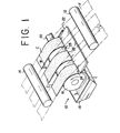
- the representative coating apparatus is generally designated 10 in FIGS. 1 and 2.
- the three fastener tapes F to be coated travel in a predetermined direction, from right to left in FIGS. 1 and 2, along a predetermined path in parallel spaced relation to one another.
- two guide rollers 12 and 14 Extending across the path of the fastener tapes F and spaced from each other in the longitudinal direction of the path, two guide rollers 12 and 14 are shown guiding such travel of the fastener tapes.
- the fastener tapes F have each a known width W and are spaced a predetermined distance S from one another.
- the coating apparatus 10 includes a coating roller 16 disposed horizontally across the predetermined path of the fastener tapes F in coating engagement with the undersides of the fastener tapes. It is understood that the fastener tapes F travel with their front sides directed upwardly, so that the rear sides of these fastener tapes are to be coated in a manner set forth hereafter.
- any known or suitable coating liquid is to be supplied to the surface of the coating roller 16 throughout its axial dimension. Toward this end the coating roller 16 is shown partly dipped in a coating liquid C contained in a pan or open top vessel 18. Mounted on a rotary shaft 20 extending axially therethrough, the coating roller 16 rotates in a counterclockwise direction as viewed in FIGS. 1 and 2.
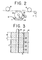
- FIG. 2 indicates that the doctor blade 22 is so angled with respect to a radial direction of the coating roller 16, and in relation to the predetermined rotational direction of the coating roller, as not to scratch or otherwise ruin the surface of the coating roller.
- the scraping edge 24 of the doctor blade 22 has defined therein a plurality of, three in this particular embodiment, recesses 26 arranged at constant spacings in the longitudinal direction of the scraping edge.
- Each recess 26 is rectangular in shape in this particular embodiment and has a length (i.e., the dimension in the longitudinal direction of the scraping edge 24) approximately equal to the width W of each fastener tape F to be coated.
- the recesses 26 are spaced from each other the same distance S as are the fastener tapes F.
- the fastener tapes F travel at a consant speed in contact with the coating roller 16 which is revolving in partial immersion in the liquid C within the open top vessel 18.
- the doctor blade 22 operates to selectively scrape the liquid C off the successive circumferential parts of the coating roller 16 before such parts come into contact with the fastener tapes F.
- only the relatively protuberant parts 28 of the scraping edge 24 scrape off the liquid, whereas the recesses 26 in the scraping edge leave the liquid in the form of bands on the coating roller 16.
- These bands of the coating liquid C left on the coatng roller 16 are each of substantially the same width as each fastener tape F and are in register with the respective fastener tapes.
- the fastener tapes F travel in contact with the bands of the coating liquid C left unscraped on.the coating roller 16 and so have their rear sides coated with the liquid.
- FIG. 4 illustrates the fastener tape F having the coating C' formed on its rear side by the coating apparatus 10 of FIGS. 1 and 2.
- the coating C' is effective to hold the hooks 30 against detachment from the carrier fabric 32. It will be seen that the coating C' covers only the rear side of the fastener tape F, without any overflow onto its front side over the selvages 34.
- the thickness of the bands of the coating liquid C left unscraped on the coating roller 16, and therefore of the coatings C' formed on the fastener tapes F depends upon the depth of the recesses 26 in the scraping edge 24 of the doctor blade 22. Any required number of interchangeable doctor blades may therefore be prepared which have the recesses 26 of varying depths, and these doctor blades may be selectively employed to create the coatings C'of required thickness on fastener tapes.
- doctor blade for use in the coating apparatus of this invention can be recessed in various ways other than that shown in FIG. 3, in order to adapt the apparatus for use with coating substances of various viscosities and for the specific requirements of each application.
- FIG. 5 shows a modified doctor blade 22a having a series of recesses 26a which are arcuate or concave in shape, instead of being rectangular as in the embodiment of FIG. 3.
- These arcuate recesses 26a result in the creation of convex bands of coating liquid C on the coating roller 16, each band becoming thinner toward its opposite lateral edges. Consequently, when fastener tapes or other strips are held against this coating roller, there is still less possibility of the coating liquid flowing onto their front sides.
- each recess 26b is defined by a sawtoothed edge of the doctor blade.
- the sawtoothed edge of the doctor blade 22b has a series of pointed sawteeth 36.
- This doctor blade 22b leaves the coating liquid C in the shape of sawteeth on the coating roller 16. If the liquid is of appropriately low viscosity, it will create a nearly flat coating on one side of a fastener tape or the like without flowing onto the other side thereof.
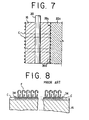
- Still another modified doctor blade 22c of FIG. 7 has each of its recesses 26c also defined by a sawtoothed edge.
- the sawtoothed edge of this doctor blade 22c has a series of truncated sawteeth 36a.
- the doctor blade 22c leaves the coating liquid C in the shape of spaced apart sawteeth on the coating roller 16.
- This doctor blade is therefore suitable for use with a coating liquid of still lower viscosity than that of the liquid used with the doctor blade 22b of FIG. 6.
- FIG. 8 shows the aforementioned prior art coating roller 38 having no recessed doctor blade taught by the present invention. Since the prior art roller 38 has its complete surface covered with the coating agent C as it makes coating contact with the fastener tapes F, the excess amounts of the coating agent have been easy to flow onto the front side of the fastener tapes over their selvages 34, resulting in the difficulties pointed out previously.
- the present invention eliminates such difficulties by the means set forth in detail hereinbefore.
Landscapes
- Engineering & Computer Science (AREA)
- Textile Engineering (AREA)
- Coating Apparatus (AREA)
- Application Of Or Painting With Fluid Materials (AREA)
Abstract
Description
- This invention relates to a coating apparatus and more specifically to an apparatus for coating one side of a plurality of strips or tapes of fabrics, plastics or any other material at one time so as to prevent the coated substance from flowing onto the other sides of the strips. The coating apparatus of this invention is of particular utility when used for applying a coating substance to the rear sides of elongate surface type fastener tapes havihg.a multiplicity of hooks or loops on their front sides, in order to firmly anchor such hooks or loops to their carrier fabric.
- The surface type fastener is known which comprises one fastener member having a mulplicity of hooks on a piece of carrier fabric, and another fastener member having a multiplicity of loops on another piece of carrier fabric. When pressed against each other, the two fastener members fasten together as a result of the interengagement of the hooks and loops. The hooks and loops are disengageable when the fastener members are forced apart from each other. In the manufacture of such surface type fasteners, fastener tapes are prepared which are elongate strips of carrier fabric each having hooks or loops on its front side. The rear sides of these fastener tapes must be coated with a liquid which, when cured, can provide a positive anchorage for the hooks or loops onto the carrier fabric.
- The usual practice in the fastener industry for coating the rear sides of the fastener tapes has been to feed a plurality or multiplicity of such fastener tapes in coplanar, parallel spaced relation to one another over a coating roller partly dipped in a coating agent contained in a pan or any other open top vessel (as will be later explained with reference to FIG. 8 of the drawings attached hereto). However, if applied to the fastener tapes from the complete surface of the coating roller, the coating agent will readily permeate the longitudinal edge portions of the fastener tapes, where they have no hooks or loops, and will thoroughly cover the selvages of the fastener tapes which need not be coated.
- So coated, the selvages of the fastener tapes will harden upon curing of the coated liquid. Surface type fasteners are usually attached to desired articles by stitching the selvages thereto. The selvages hardened by excessive coating as above make this stitching difficult and so impair the commercial value of the fasteners.
- Japanese Laid Open Patent Application No. 59-228970 and Japanese Laid Open Utility Model Application No. 59-150561 suggest a solution to this problem, both teaching the creation of a plurality of circumferential channels in the surface of a coating roller partly dipped in a desired coating liquid. As the strips to be coated are fed in rolling engagement with the channeled coating roller, the liquid is applied to the strips from the channels.
- An objection to this known apparatus is that the thickness and width of the coatings on the strips are determined by the depth and width of the channels in the coating roller. Consequently, many coating rollers having different numbers, widths and depths of channels must be manufactured and held in stock for coating different numbers and widths of strips to different thicknesses. This conventional coating apparatus is therefore not adaptable for a variety of applications without necessitating much cost for the manufacture of many differently channeled coating rollers which
- The present invention provides an improved coating apparatus whereby a desired coating agent can be applied to only one side of each of a plurality or multiplicity of surface type fastener tapes or other strips, without the possibility of the coating agent flowing onto the other sides of the strips. The improved apparatus of this invention is notable for its ready adaptability for a variety of specific coating applications and requirements.at reduced cost.
- Briefly, the invention may be summarized as a coating apparatus for simultaneously applying a desired coating substance to a plurality of surface type fastener tapes or like strips, each having a known width, traveling in a predetermined direction along a predetermined path in parallel relation to each other and with a predetermined spacing therebetween. The coating apparatus comprises a coating roller disposed across the predetermined path of the strips so as to be in coating contact therewith. A supply means is provided for constantly supplying the coating substance over the surface of the coating roller. Also included is a doctor blade having a scraping edge held against the surface of the coating roller for selectively scraping off the coating substance therefrom. The scraping edge of the doctor blade has defined therein a series of recesses each having a length approximately equal to the width of each strip, the recesses having a spacing therebetween which is approximately equal to the spacing between the strips being coated.
- Preferably, the supply means takes the form of an open top vessel containing the coating liquid, in which the coating roller is partly dipped, so that the coating liquid is applied to the surface of the coating roller throughout its axial length. The doctor blade with its recessed scraping edge operates to scrape off the liquid from those surface portions of the coating roller which do not make contact with the strips. The recesses in the scraping edge leave the coating liquid on the coating roller in the shape of bands which are each of approximately the same width as each strip and which have approximately the same spacing therebetween as that between the strips. Travelling in contact with these bands of the coating liquid, the strips have only their required sides coated with the liquid. There is practically no likelihood of the coating substance intruding onto the other sides of the strips over their longitudinal edges, because only a required amount of the substance is applied to each strip from a required surface portion of the coating roller.
- The selective doctoring of the coating agent off the coating roller in accordance with the invention offers an additional advantage. Should the coating substance be left unscraped from the unrequired surface portions of the coating roller, the substance on these unrequired surface portions would be denatured through overexposure to the atmosphere. The denatured substance would then return to the vessel, thereby accelerating the denaturation of the complete substance within the vessel. The present invention precludes this danger and extends the useful life of the coating substance.
- The recesses in the scraping edge of the doctor blade may each be either rectangualar or arcuate in shape. Alternatively, the doctor blade edges defining the recesses may be sawtoothed for use with a coating agent of relatively low viscosity. It is also possible to truncate the sawteeth for use with a coating agent of still lower viscosity. Many doctor blades having recesses of such various shapes and depths may be prepared to regulate the amounts of the liquid to be left on the coating roller and hence to be coated on the strips. Thus the liquid will be applied to the strips in an optimum manner determined in part by its viscosity.
- Doctor blades having the recesses af various lengths may also be prepared for coating strips of various widths. Although the coating apparatus of this invention requires the preparation of many interchangeable doctor blades for adaptability to different applications and applications, such doctor blades are far less costly than the interchangeable coating rollers required by the prior art set forth previously.
- The above and other features and advantages of this invention and the manner of realizing them will become more apparent, and the invention itself will best be understood, from a study of the following description and appended claims, with reference had to the attached drawings showing some preferable embodiments of the invention.
-
- FIG. 1 is a diagrammatic perspective view, partly shown broken away for illustrative convenience, of a coating apparatus constructed in accordance with the novel concepts of this invention;
- FIG. 2 is a diagrammatic side elevation of the coating apparatus of FIG. 1;
- FIG. 3 is an enlarged axial section through the coating roller in the coating apparatus of FIG. 1, shown together with part of the doctor blade having the recessed scraping edge held against the coating roller;
- FIG. 4 is an enlarged transverse section, shown partly broken away for illustrative convenience, through one of the fastener tapes coated by the apparatus of FIG. 1;
- FIG. 5 is a view similar to FIG. 3 but showing a modified doctor blade;
- FIG. 6 is also a view similar to FIG. 3 but showing another modified doctor blade;
- FIG. 7 is also a view similar to FIG. 3 but showing still another modified doctor blade; and
- FIG. 8 is a fragmentary axial section through a prior art coating roller shown together with fastener tapes being coated.
- The coating apparatus of this invention will now be described in detail as adapted, by way of example only, for simultaneously coating three surface type fastener tapes. The representative coating apparatus is generally designated 10 in FIGS. 1 and 2. As will be seen from these figures, the three fastener tapes F to be coated travel in a predetermined direction, from right to left in FIGS. 1 and 2, along a predetermined path in parallel spaced relation to one another. Extending across the path of the fastener tapes F and spaced from each other in the longitudinal direction of the path, two
guide rollers - The
coating apparatus 10 includes acoating roller 16 disposed horizontally across the predetermined path of the fastener tapes F in coating engagement with the undersides of the fastener tapes. It is understood that the fastener tapes F travel with their front sides directed upwardly, so that the rear sides of these fastener tapes are to be coated in a manner set forth hereafter. - Any known or suitable coating liquid is to be supplied to the surface of the
coating roller 16 throughout its axial dimension. Toward this end thecoating roller 16 is shown partly dipped in a coating liquid C contained in a pan oropen top vessel 18. Mounted on arotary shaft 20 extending axially therethrough, thecoating roller 16 rotates in a counterclockwise direction as viewed in FIGS. 1 and 2. - At 22 in both FIGS. 1 and 2 is shown a doctor blade having a
scraping edge 24 held against the surface of thecoating roller 16 for selectively-scraping off the coating liquid C therefrom in accordance with the principles of this invention. FIG. 2 indicates that thedoctor blade 22 is so angled with respect to a radial direction of thecoating roller 16, and in relation to the predetermined rotational direction of the coating roller, as not to scratch or otherwise ruin the surface of the coating roller. - As better illustrated on an enlarged scale in FIG. 3, the scraping
edge 24 of thedoctor blade 22 has defined therein a plurality of, three in this particular embodiment, recesses 26 arranged at constant spacings in the longitudinal direction of the scraping edge. Eachrecess 26 is rectangular in shape in this particular embodiment and has a length (i.e., the dimension in the longitudinal direction of the scraping edge 24) approximately equal to the width W of each fastener tape F to be coated. Therecesses 26 are spaced from each other the same distance S as are the fastener tapes F. Thus thedoctor blade 22 selectively scrapes the coating liquid C off thecoating roller 22 only with the relativelyprotuberant parts 28 of itsscraping edge 24 left between therecesses 26. - Guided by the
guide rollers coating roller 16 which is revolving in partial immersion in the liquid C within the opentop vessel 18. Thedoctor blade 22 operates to selectively scrape the liquid C off the successive circumferential parts of thecoating roller 16 before such parts come into contact with the fastener tapes F. As will be seen from FIG. 3, only the relativelyprotuberant parts 28 of the scrapingedge 24 scrape off the liquid, whereas therecesses 26 in the scraping edge leave the liquid in the form of bands on thecoating roller 16. These bands of the coating liquid C left on thecoatng roller 16 are each of substantially the same width as each fastener tape F and are in register with the respective fastener tapes. Thus the fastener tapes F travel in contact with the bands of the coating liquid C left unscraped on.thecoating roller 16 and so have their rear sides coated with the liquid. - FIG. 4 illustrates the fastener tape F having the coating C' formed on its rear side by the
coating apparatus 10 of FIGS. 1 and 2. The coating C' is effective to hold thehooks 30 against detachment from thecarrier fabric 32. It will be seen that the coating C' covers only the rear side of the fastener tape F, without any overflow onto its front side over theselvages 34. - As will be seen by referring back to FIG. 3, the thickness of the bands of the coating liquid C left unscraped on the
coating roller 16, and therefore of the coatings C' formed on the fastener tapes F, depends upon the depth of therecesses 26 in the scrapingedge 24 of thedoctor blade 22. Any required number of interchangeable doctor blades may therefore be prepared which have therecesses 26 of varying depths, and these doctor blades may be selectively employed to create the coatings C'of required thickness on fastener tapes. - There may also be prepared a suitable stock of interchangeable doctor blades having the
recesses 26 of different lengths. Then thecoating apparatus 10 will be readily adaptable for coating fastener tapes or other strips of various widths. - The doctor blade for use in the coating apparatus of this invention can be recessed in various ways other than that shown in FIG. 3, in order to adapt the apparatus for use with coating substances of various viscosities and for the specific requirements of each application.
- FIG. 5 shows a modified doctor blade 22a having a series of recesses 26a which are arcuate or concave in shape, instead of being rectangular as in the embodiment of FIG. 3. These arcuate recesses 26a result in the creation of convex bands of coating liquid C on the
coating roller 16, each band becoming thinner toward its opposite lateral edges. Consequently, when fastener tapes or other strips are held against this coating roller, there is still less possibility of the coating liquid flowing onto their front sides. - In another modified
doctor blade 22b shown in FIG: 6, eachrecess 26b is defined by a sawtoothed edge of the doctor blade. The sawtoothed edge of thedoctor blade 22b has a series ofpointed sawteeth 36. Thisdoctor blade 22b leaves the coating liquid C in the shape of sawteeth on thecoating roller 16. If the liquid is of appropriately low viscosity, it will create a nearly flat coating on one side of a fastener tape or the like without flowing onto the other side thereof. - Still another modified
doctor blade 22c of FIG. 7 has each of itsrecesses 26c also defined by a sawtoothed edge. The sawtoothed edge of thisdoctor blade 22c, however, has a series of truncated sawteeth 36a. As a result, thedoctor blade 22c leaves the coating liquid C in the shape of spaced apart sawteeth on thecoating roller 16. This doctor blade is therefore suitable for use with a coating liquid of still lower viscosity than that of the liquid used with thedoctor blade 22b of FIG. 6. - FIG. 8 shows the aforementioned prior art coating roller 38 having no recessed doctor blade taught by the present invention. Since the prior art roller 38 has its complete surface covered with the coating agent C as it makes coating contact with the fastener tapes F, the excess amounts of the coating agent have been easy to flow onto the front side of the fastener tapes over their
selvages 34, resulting in the difficulties pointed out previously. The present invention eliminates such difficulties by the means set forth in detail hereinbefore. - Although it has already been mentioned, it must be borne in mind that the fastener tape coating apparatus herein disclosed has been chosen with the thought of pictorially presenting the principles of the present invention in conjunction with the resulting advantages gained in this particular application. Thus the illustrated apparatus may be modified or altered within the scope of the invention to conform to design preferences or to the specific requirements of each intended application.
Claims (7)
Applications Claiming Priority (2)
| Application Number | Priority Date | Filing Date | Title |
|---|---|---|---|
| JP1985172334U JPH0414149Y2 (en) | 1985-11-11 | 1985-11-11 | |
| JP172334/85 | 1985-11-11 |
Publications (3)
| Publication Number | Publication Date |
|---|---|
| EP0222594A2 true EP0222594A2 (en) | 1987-05-20 |
| EP0222594A3 EP0222594A3 (en) | 1988-03-30 |
| EP0222594B1 EP0222594B1 (en) | 1990-06-06 |
Family
ID=15939973
Family Applications (1)
| Application Number | Title | Priority Date | Filing Date |
|---|---|---|---|
| EP86308635A Expired - Lifetime EP0222594B1 (en) | 1985-11-11 | 1986-11-05 | Apparatus for simultaneously coating a plurality of surface type fastener tapes or like strips |
Country Status (10)
| Country | Link |
|---|---|
| US (1) | US4892760A (en) |
| EP (1) | EP0222594B1 (en) |
| JP (1) | JPH0414149Y2 (en) |
| KR (1) | KR920008645Y1 (en) |
| AU (1) | AU597283B2 (en) |
| CA (1) | CA1269827A (en) |
| DE (1) | DE3671765D1 (en) |
| HK (1) | HK58793A (en) |
| MY (1) | MY100619A (en) |
| SG (1) | SG41593G (en) |
Cited By (1)
| Publication number | Priority date | Publication date | Assignee | Title |
|---|---|---|---|---|
| GB2325422A (en) * | 1997-05-20 | 1998-11-25 | Ykk Europ Ltd | Intermittently coating a tape |
Families Citing this family (8)
| Publication number | Priority date | Publication date | Assignee | Title |
|---|---|---|---|---|
| US5266142A (en) * | 1991-11-01 | 1993-11-30 | Decc Technology Partnership A Limited Partnership | Coated piston and method and apparatus of coating the same |
| US5435873A (en) * | 1991-11-01 | 1995-07-25 | Decc Technology Partnership, A Limited Partnership Of Which The Decc Company, Inc. Is A General Partner | Method and apparatus for sizing a piston |
| US5435872A (en) * | 1991-11-01 | 1995-07-25 | Decc Technology Partnership | Sized coated pistons |
| US6495267B1 (en) | 2001-10-04 | 2002-12-17 | Briggs & Stratton Corporation | Anodized magnesium or magnesium alloy piston and method for manufacturing the same |
| CN102553773B (en) * | 2012-02-21 | 2013-11-13 | 驰马拉链(无锡)有限公司 | Oil wheel device for colored coating machine for surface of metal zipper |
| KR101453981B1 (en) * | 2013-09-06 | 2014-11-03 | 케이피피지퍼 주식회사 | Apparatus for treating surface of slide fastener chain |
| CN105772319B (en) * | 2014-12-18 | 2018-06-26 | 驰马拉链(安徽)有限公司 | A kind of dedicated device of tinting of slide fastener |
| CN109926264A (en) * | 2019-04-10 | 2019-06-25 | 武汉福赛尔新能源科技有限公司 | A kind of surface covering device of micro-tubular solid oxide fuel cell |
Citations (2)
| Publication number | Priority date | Publication date | Assignee | Title |
|---|---|---|---|---|
| GB1349725A (en) * | 1971-08-02 | 1974-04-10 | Ilford Ltd | Transfer roller coating apparatus |
| JPS59150560U (en) * | 1983-03-24 | 1984-10-08 | 日新製鋼株式会社 | Partial coating equipment for strips |
Family Cites Families (5)
| Publication number | Priority date | Publication date | Assignee | Title |
|---|---|---|---|---|
| US2079563A (en) * | 1934-11-27 | 1937-05-04 | Hookless Fastener Co | Method and apparatus for coating slide fasteners |
| US2754796A (en) * | 1953-09-10 | 1956-07-17 | Rock Hill Printing & Finishing | Design coloring means for fabric material |
| AU4881569A (en) * | 1969-01-08 | 1971-07-15 | Nid Pty. Limited | Caramel applicator |
| JPS59150561A (en) * | 1983-02-18 | 1984-08-28 | Hitachi Ltd | Centrifugal separator |
| JPS59228970A (en) * | 1983-06-11 | 1984-12-22 | Daido Kohan Kk | Method and device for painting |
-
1985
- 1985-11-11 JP JP1985172334U patent/JPH0414149Y2/ja not_active Expired
-
1986
- 1986-11-03 AU AU64657/86A patent/AU597283B2/en not_active Ceased
- 1986-11-05 EP EP86308635A patent/EP0222594B1/en not_active Expired - Lifetime
- 1986-11-05 DE DE8686308635T patent/DE3671765D1/en not_active Expired - Lifetime
- 1986-11-05 KR KR2019860017153U patent/KR920008645Y1/en not_active IP Right Cessation
- 1986-11-10 CA CA000522550A patent/CA1269827A/en not_active Expired - Lifetime
- 1986-11-11 MY MYPI86000082A patent/MY100619A/en unknown
-
1988
- 1988-12-02 US US07/279,109 patent/US4892760A/en not_active Expired - Fee Related
-
1993
- 1993-04-08 SG SG415/93A patent/SG41593G/en unknown
- 1993-06-17 HK HK587/93A patent/HK58793A/en unknown
Patent Citations (2)
| Publication number | Priority date | Publication date | Assignee | Title |
|---|---|---|---|---|
| GB1349725A (en) * | 1971-08-02 | 1974-04-10 | Ilford Ltd | Transfer roller coating apparatus |
| JPS59150560U (en) * | 1983-03-24 | 1984-10-08 | 日新製鋼株式会社 | Partial coating equipment for strips |
Cited By (4)
| Publication number | Priority date | Publication date | Assignee | Title |
|---|---|---|---|---|
| GB2325422A (en) * | 1997-05-20 | 1998-11-25 | Ykk Europ Ltd | Intermittently coating a tape |
| ES2154977A1 (en) * | 1997-05-20 | 2001-04-16 | Ykk Corp | Apparatus and method for intermittently coating a tape |
| US6221158B1 (en) | 1997-05-20 | 2001-04-24 | Ykk Corporation | Apparatus and method for intermittently coating a tape |
| GB2325422B (en) * | 1997-05-20 | 2001-09-05 | Ykk Europ Ltd | Apparatus and method for intermittently coating a tape |
Also Published As
| Publication number | Publication date |
|---|---|
| MY100619A (en) | 1990-12-29 |
| KR870008102U (en) | 1987-06-10 |
| DE3671765D1 (en) | 1990-07-12 |
| SG41593G (en) | 1993-06-11 |
| HK58793A (en) | 1993-06-25 |
| AU6465786A (en) | 1987-05-14 |
| US4892760A (en) | 1990-01-09 |
| JPH0414149Y2 (en) | 1992-03-31 |
| EP0222594A3 (en) | 1988-03-30 |
| JPS6283575U (en) | 1987-05-28 |
| KR920008645Y1 (en) | 1992-12-12 |
| CA1269827A (en) | 1990-06-05 |
| AU597283B2 (en) | 1990-05-31 |
| EP0222594B1 (en) | 1990-06-06 |
Similar Documents
| Publication | Publication Date | Title |
|---|---|---|
| EP0222594B1 (en) | Apparatus for simultaneously coating a plurality of surface type fastener tapes or like strips | |
| US5031569A (en) | Apparatus for coating a travelling web | |
| US3006317A (en) | Knurled strip adhesive applying device | |
| US3669070A (en) | Dispensing device for dry wall tape and joint cement | |
| EP0228238B1 (en) | Apparatus for coating one side of one or more surface type fastener tapes or like strips | |
| US4132617A (en) | Apparatus for continuous application of strip-, ribbon- or patch-shaped coatings to a metal tape | |
| SE8503602D0 (en) | PROCEDURE FOR FLUIDITY REQUIREMENTS, SPECIFIC PAINTING UNIT FOR A PRINTING MACHINE | |
| US2079563A (en) | Method and apparatus for coating slide fasteners | |
| GB2034203A (en) | Applicator Bar | |
| US3899615A (en) | Method of coating paper or other sheet material with surface layers of different coating compositions | |
| US20100242839A1 (en) | Apparatus for applying a liquid to a passing web | |
| JPS6291266A (en) | Adhesive coating head | |
| JP2514847B2 (en) | Coating device | |
| DE3212152A1 (en) | Apparatus for selectively electroplating a strip | |
| EP0750535A4 (en) | Razor blade manufacture | |
| FI850473A0 (en) | BELAEGGNINGSANORDNING FOER MATERIALBANOR. | |
| GB2174625A (en) | Trailing blade web coater | |
| DE2720244A1 (en) | Blade for applying paint to flat surfaces - has internal passageways to ensure even distribution and gap and hole dimensions ensure even paint flow | |
| US5622560A (en) | Device for uniformly moistening adhesive labels | |
| FI110170B (en) | Bladbestrykningsmaskin | |
| JPS6291267A (en) | Coater head assembly | |
| DE3927365A1 (en) | Applicator roller for coating low viscosity adhesive on foil - carries specified intersecting spiral grooves on its surface | |
| JP2630491B2 (en) | Method and apparatus for coating grooved plate | |
| JPH0771657B2 (en) | Adhesive stripe coating method | |
| JP4839576B2 (en) | Coating method for strips |
Legal Events
| Date | Code | Title | Description |
|---|---|---|---|
| PUAI | Public reference made under article 153(3) epc to a published international application that has entered the european phase |
Free format text: ORIGINAL CODE: 0009012 |
|
| AK | Designated contracting states |
Kind code of ref document: A2 Designated state(s): DE FR GB IT |
|
| 17P | Request for examination filed |
Effective date: 19870708 |
|
| PUAL | Search report despatched |
Free format text: ORIGINAL CODE: 0009013 |
|
| AK | Designated contracting states |
Kind code of ref document: A3 Designated state(s): DE FR GB IT |
|
| 17Q | First examination report despatched |
Effective date: 19890728 |
|
| GRAA | (expected) grant |
Free format text: ORIGINAL CODE: 0009210 |
|
| AK | Designated contracting states |
Kind code of ref document: B1 Designated state(s): DE FR GB IT |
|
| ITF | It: translation for a ep patent filed |
Owner name: JACOBACCI & PERANI S.P.A. |
|
| REF | Corresponds to: |
Ref document number: 3671765 Country of ref document: DE Date of ref document: 19900712 |
|
| ET | Fr: translation filed | ||
| PLBE | No opposition filed within time limit |
Free format text: ORIGINAL CODE: 0009261 |
|
| STAA | Information on the status of an ep patent application or granted ep patent |
Free format text: STATUS: NO OPPOSITION FILED WITHIN TIME LIMIT |
|
| 26N | No opposition filed | ||
| ITTA | It: last paid annual fee | ||
| PGFP | Annual fee paid to national office [announced via postgrant information from national office to epo] |
Ref country code: FR Payment date: 19940923 Year of fee payment: 9 |
|
| PGFP | Annual fee paid to national office [announced via postgrant information from national office to epo] |
Ref country code: GB Payment date: 19941026 Year of fee payment: 9 |
|
| PGFP | Annual fee paid to national office [announced via postgrant information from national office to epo] |
Ref country code: DE Payment date: 19941130 Year of fee payment: 9 |
|
| ITPR | It: changes in ownership of a european patent |
Owner name: CAMBIO RAGIONE SOCIALE;YKK CORPORATION |
|
| REG | Reference to a national code |
Ref country code: FR Ref legal event code: CD |
|
| PG25 | Lapsed in a contracting state [announced via postgrant information from national office to epo] |
Ref country code: GB Effective date: 19951105 |
|
| GBPC | Gb: european patent ceased through non-payment of renewal fee |
Effective date: 19951105 |
|
| PG25 | Lapsed in a contracting state [announced via postgrant information from national office to epo] |
Ref country code: FR Effective date: 19960731 |
|
| PG25 | Lapsed in a contracting state [announced via postgrant information from national office to epo] |
Ref country code: DE Effective date: 19960801 |
|
| REG | Reference to a national code |
Ref country code: FR Ref legal event code: ST |
|
| PG25 | Lapsed in a contracting state [announced via postgrant information from national office to epo] |
Ref country code: IT Free format text: LAPSE BECAUSE OF NON-PAYMENT OF DUE FEES;WARNING: LAPSES OF ITALIAN PATENTS WITH EFFECTIVE DATE BEFORE 2007 MAY HAVE OCCURRED AT ANY TIME BEFORE 2007. THE CORRECT EFFECTIVE DATE MAY BE DIFFERENT FROM THE ONE RECORDED. Effective date: 20051105 |