EP0222540A2 - Automatische Materialprobenentnahmevorrichtung - Google Patents
Automatische Materialprobenentnahmevorrichtung Download PDFInfo
- Publication number
- EP0222540A2 EP0222540A2 EP86308247A EP86308247A EP0222540A2 EP 0222540 A2 EP0222540 A2 EP 0222540A2 EP 86308247 A EP86308247 A EP 86308247A EP 86308247 A EP86308247 A EP 86308247A EP 0222540 A2 EP0222540 A2 EP 0222540A2
- Authority
- EP
- European Patent Office
- Prior art keywords
- cross
- collection member
- flow
- collection
- sectional
- Prior art date
- Legal status (The legal status is an assumption and is not a legal conclusion. Google has not performed a legal analysis and makes no representation as to the accuracy of the status listed.)
- Granted
Links
- 239000000463 material Substances 0.000 title claims abstract description 116
- 238000005070 sampling Methods 0.000 claims abstract description 89
- 238000007789 sealing Methods 0.000 claims description 20
- 238000004891 communication Methods 0.000 claims description 13
- 238000010926 purge Methods 0.000 claims description 13
- 230000004044 response Effects 0.000 claims description 4
- 238000010276 construction Methods 0.000 description 13
- 239000000203 mixture Substances 0.000 description 11
- 230000007246 mechanism Effects 0.000 description 7
- 230000007704 transition Effects 0.000 description 6
- 230000002411 adverse Effects 0.000 description 4
- 239000004568 cement Substances 0.000 description 3
- 239000000470 constituent Substances 0.000 description 3
- 239000000428 dust Substances 0.000 description 3
- 230000002093 peripheral effect Effects 0.000 description 3
- 239000002002 slurry Substances 0.000 description 3
- 239000007787 solid Substances 0.000 description 3
- 230000008901 benefit Effects 0.000 description 2
- 230000008878 coupling Effects 0.000 description 2
- 238000010168 coupling process Methods 0.000 description 2
- 238000005859 coupling reaction Methods 0.000 description 2
- 229920001821 foam rubber Polymers 0.000 description 2
- 239000007789 gas Substances 0.000 description 2
- 239000007788 liquid Substances 0.000 description 2
- 238000000034 method Methods 0.000 description 2
- 238000002156 mixing Methods 0.000 description 2
- 230000008569 process Effects 0.000 description 2
- 230000000717 retained effect Effects 0.000 description 2
- 239000000126 substance Substances 0.000 description 2
- 239000004698 Polyethylene Substances 0.000 description 1
- 229910000831 Steel Inorganic materials 0.000 description 1
- 238000005299 abrasion Methods 0.000 description 1
- 230000009471 action Effects 0.000 description 1
- 238000004140 cleaning Methods 0.000 description 1
- 230000002860 competitive effect Effects 0.000 description 1
- 238000010586 diagram Methods 0.000 description 1
- 230000000694 effects Effects 0.000 description 1
- 229920001971 elastomer Polymers 0.000 description 1
- 239000000806 elastomer Substances 0.000 description 1
- 238000007373 indentation Methods 0.000 description 1
- 210000002445 nipple Anatomy 0.000 description 1
- 239000004033 plastic Substances 0.000 description 1
- 229920003023 plastic Polymers 0.000 description 1
- -1 polyethylene Polymers 0.000 description 1
- 229920000573 polyethylene Polymers 0.000 description 1
- 238000010008 shearing Methods 0.000 description 1
- 239000010959 steel Substances 0.000 description 1
- 238000003466 welding Methods 0.000 description 1
Images



Classifications
-
- G—PHYSICS
- G01—MEASURING; TESTING
- G01N—INVESTIGATING OR ANALYSING MATERIALS BY DETERMINING THEIR CHEMICAL OR PHYSICAL PROPERTIES
- G01N1/00—Sampling; Preparing specimens for investigation
- G01N1/02—Devices for withdrawing samples
- G01N1/10—Devices for withdrawing samples in the liquid or fluent state
- G01N1/20—Devices for withdrawing samples in the liquid or fluent state for flowing or falling materials
- G01N1/2035—Devices for withdrawing samples in the liquid or fluent state for flowing or falling materials by deviating part of a fluid stream, e.g. by drawing-off or tapping
-
- G—PHYSICS
- G01—MEASURING; TESTING
- G01N—INVESTIGATING OR ANALYSING MATERIALS BY DETERMINING THEIR CHEMICAL OR PHYSICAL PROPERTIES
- G01N1/00—Sampling; Preparing specimens for investigation
- G01N1/02—Devices for withdrawing samples
- G01N1/10—Devices for withdrawing samples in the liquid or fluent state
- G01N1/20—Devices for withdrawing samples in the liquid or fluent state for flowing or falling materials
- G01N2001/2092—Cross-cut sampling
Definitions
- This invention relates generally to sampling apparatus for gathering a representative sample of flowing material and more particularly, but not by way of limitation, to an automatic sampling apparatus that obtains a full cross-sectional sample within a positively or negatively pressurized (i.e. above or below atmospheric pressure) pipe or duct system.
- apparatus for sampling material flowing through a conduit comprising: housing means for receiving therethrough a flow of the material as the material flows through the conduit, said housing means including cross-section defining means for defining a full cross-sectional sample area, receptacle means for receiving a collection member outside said defined cross-sectional sample area, and connector means for connecting said cross-section defining means to the conduit so that the cross-sectional sample area defined by said cross-section defining means is aligned with the cross-section of the conduit; and sampler means, connected with said housing means, for collecting a full cross-sectional sample of the material as the material flows through said cross-section defining means of said housing means under pressure, said sampler means including: said collection member disposed in said housing means for receiving a portion of the flowing material; and movement means for moving said collection member from a location outside the full cross-sectional sample area of the material across the full cross-sectional flow sample area of the material, so that it receives said portion of said flowing material as it passes therea
- the collection member comprises an elongated inlet element with inlet means for receiving said portion of the flowing material; and wherein there is provided a flow line connected to said collection member, said flow line having a first sample flow channel and a first purge channel defined therein; said inlct element of said collection member having a second sample flow channel defined therein in communication with said inlet means and said first sample flow channel, and a second purge channel defined therein in communication with said inlet means and said first purge channel.
- said collection member includes a shaft and a plurality of vanes connected to said shaft. in spaced relation to each other so that any two adjacent vanes define an area which includes the cross-sectional area of the pressurized flow of the material; and wherein said movement means provides rotational motion for rotating the shaft of said collection member whereby said vanes are moved from a location outside the full cross-sectional sample area of the material, across the full cross-sectional, pressurized flow sample area of the material.
- the invention also provides a material sampling apparatus comprising: an elongated collection member having a collection channel defined therein for receiving a sample of material and including a body having an inlet portion in which an inlet opening is defined transversely to the direction of flow of the material to be sampled, said body further having a neck portion extending from said inlet portion, said inlet and neck portions having said collection channel defined therethrough; flow path insert means for inserting said apparatus into a line through which the material to be sampled flows, said insert means including: a sampling window member having a hollow interior including a cross-sectional area defining a sampling window; adapter means for connecting said sampling window member into the line through which the material to be sampled flows; and receptacle means, communicating with the hollow interior of said sampling window member, for receiving said collection member in a non-sampling position outside said sampling window; a flow line connected to and extending from said neck portion of said collection member and from said flow path insert means; seal means for providing a pressure seal between said flow line and said flow path insert means
- pressurized refers to a non-atmospheric pressure, i.e. a positive pressure greater than atmospheric pressure of a negative or evacuated pressure less than atmospheric pressure.
- Apparatus of the present invention can be constructed relatively inexpensively. Furthermore, operation of the apparatus can be effected without significant adverse effect on the primary flow of material.
- each of these embodiments includes housing means for receiving a pressurized (as previously defined, either positively or negatively pressurized) flow of the material to be sampled as it flows through a conduit, such as a pipe or duct, into which the apparatus is connected in an in-line or aligned configuration (i.e. the apparatus becomes part of the primary flow path of the flowing material).
- the present invention also includes sampler means for collecting a full cross-sectional sample of the material as the material flows through the housing means under pressure.
- the sampler means includes a collection member disposed in the housing means, and it further includes movement means for moving the collection member, from a location outside the full cross-sectional flow sample area of the material, across the full cross-sectional, pressurized flow sample area of the material.
- the housing means includes cross-section defining means for defining the cross-sectional-sample area across which the collection member is movable, and it also includes connector means for connecting the cross-section defining means to the conduit so that the cross-sectional sample area defined by the cross-section defining means is aligned with the cross section of the conduit.
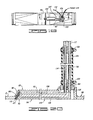
- FIGS. 1-17 A first preferred embodiment is illustrated in FIGS. 1-17. Because the housing means of the present invention is inserted into the flow path of the material to be sampled, the housing means can be said to define a flow path insert means for inserting the apparatus into the line through which the material to be sampled flows.
- this housing means, or flow path insert means includes a sampling window member 2 and receptacle means 4 for receiving the collection member in a non-sampling position outside the sampling window defined by the sampling window member 2.
- the elements 2, 4 define the cross-section defining means of the first preferred embodiment.
- Adapter means is used in this embodiment as the connector means for connecting the sampling window member 2 and receptacle means 4 into the line through which the material to be sampled flows.
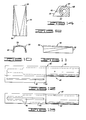
- the sampling window member 2 of the first preferred embodiment is particularly shown in FIG. 7.
- the member 2 includes a rectangular outlet plate 6 defining a side wall of the member 2.
- the plate 6 has a slot 8 defined therein.
- the slot 8 is elongated and has a notch or key portion 9 at the top for receiving the collection member as subsequently described hereinbelow; however, the portion 9 may be deleted when the collection member is constructed so that it can be manipulated or otherwise moved through a straight slot.
- the slot 8 extends parallel to the height of a rectangular area defined within the sampling window member 2. Stated differently, the slot 8 extends transversely to the width of such rectangular area. The length of the slot 8 is not less than the height of the subsequently described sampling window area.
- the outlet plate 6 is connected, such as by welding, to an L-shaped bracket 10 having legs defining a side wall 12 and a side wall 14 of the member 2.
- the side wall 12 extends parallel to the plate 6.
- the side wall 12 is spaced from the plate 6 by the side wall 14 extending perpendicularly therebetween.
- the receptacle means 4 which in this preferred embodiment includes a bifurcated plate 16 having two portions connected by a semicircular member 18 defining a receptacle 20 having a beveled front surface 22 as shown in F IG. 8.
- Attached to the surface 22 is a seal member 23, such as a foam rubber strip.
- the interior surfaces of the elements 6, 12, 14, 16 define a rectangular flow area through which the material to be sampled can flow.
- a rectangular cross-sectional sample area, or sampling window, 24 (see FIG. 7). This area is coextensive with the area swept by an inlet opening in the collection member subsequently described.
- the area 24 is substantially the same as the maximum potential flow area of the material; therefore, the present invention is defined as having the capability of obtaining a full cross-sectional sample of the flowing material, wherein "full" is not intended to mean necessarily the maximum cross-sectional area, but rather to mean simply an area by which a sufficiently representative sample of the complete flow can be obtained.
- the area 24 lies within a plane extending perpendicular to the direction of the primary flow of the material to be sampled. Although the area 24 of this embodiment is rectangular, it is contemplated that other cross-sectional shapes can be accommodated by the present invention in varying aspects.
- the adapter means by which the cross-section defining means is connected into the line or conduit containing the primary flow of material includes two adapter members 26 and. 28.
- Each adapter member 26, 28 has a transition section 30 having a polygonal end to which is connected a suitable circular coupling element 32, such as a Victaulic clamp nipple.
- the other end of the transition section 30 has a rectangular opening communicating with the rectangular cross-sectional area 24.
- the rectangular end of the transition section 30 of the member 26 is welded to the inlet side of the sampling window member 2 and receptacle means 4 combination and the rectangular end of the member 28 is welded to the outlet side of the combination.
- the transition section 30 is constructed of two similar half-sleeve members, one of which is shown in FIGS. 9-11 and identified by the reference numeral 34.
- FIGS. 9-11 show that each member 34 has one polygonal forming end 36 and one rectangular forming end 38. These shapes are used to adapt this embodiment for use in circular conveying lines of types normally used for pneumatically or otherwise conveying materials of the type to be sampled by the present invention.
- the circular cross section of such a line is converted into the rectangular cross section including the area 24 through which the collection member of the sampler means of this embodiment can be readily moved for obtaining a full cross-sectional sample of the flowing material.
- FIGS. 12-14 The collection member of the preferred embodiment shown in FIGS. 1-17 is particularly illustrated in FIGS. 12-14.
- This member is generally identified in these drawings by the reference numeral 40.
- the member 40 includes a body 42 having a beveled or angular inlet face or surface portion 44 in which inlet means is defined for receiving as a sample a portion of the flowing material.
- the inlet means includes an elongated slot 46; however, other types of openings, such as multiple slots or holes, may be used.
- the slot 46 extends laterally across the width of the cross-sectional area 24, and thus transversely to the flow of material, when the member 40 is disposed in the cross-section defining means such as is illustrated in FIG. 15.
- the body 42 of the preferred embodiment is elongated so that it presents only a small cross-sectional obstruction in the primary flow path whereby the primary flow is not substantially adversely affected when the body 42 is moved within the sampling cross-sectional area.
- This elongated body extends longitudinally from the face portion 44 into a neck portion 48 having a central bore defined therethrough in communication with the slot 46.
- the neck portion 48 terminates in an outlet opening 50 to which a flow line 52 (FIGS. 1 and 2) is connected.
- the flow line 52 is a hose or other suitable tubing or the like having an interior channel or opening through which the collected sample can be conveyed from the collection member 40 to a sample collecting container or jar 54.
- a dust filter 56 Associated with the jar 54 in the first illustrated embodiment is a dust filter 56 through which air collected with the sample is filtered by a paper filter and vented to atmosphere. It is contemplated that a suitable purging apparatus can be used with or incorporated in this embodiment for purging the dust filter 56.
- the collection member 40 is disposed within the cross-section defining means as illustrated in FIG. 15.
- the neck portion 48 extends therefrom through the slot 8 to the flow line 52 which extends to the sample jar 54 as shown in FIGS. 1 and 2.
- the preferred embodiment must include a suitable pressure seal by means of which the slot 8 can be sealed around the neck portion 48 so that material and pressure do not escape from or enter into the hollow interior of the housing means.
- such seal means includes a seal plate 58 and means for retaining the seal plate 58 in sealing engagement with the plate 6 of the sampling window member 2.
- the seal plate 58 is best viewed in FIGS. 3 and 5, wherein the seal plate 58 is shown to be a rectangular plate having a central circular aperture 60 defined therethrough.
- the aperture 60 has an inner diameter substantially the same as the outer diameter of the neck portion 48 of the collection member 40, or it is otherwise constructed to provide a suitable seal between the plate 58 and the neck portion 48.
- the plate 58 is disposed adjacent the plate 6 between a plurality of outwardly extending bolts 62.
- the seal plate 58 is made of any suitable substance which will establish a movable pressure seal adjacent the slot 8.
- UHMW ultra-high molecular weight
- polyethylene provides a suitable abrasion-resistant substance of which the seal plate 58 can be made.
- the means for retaining the seal plate 58 adjacent the plate 6 includes one of two alternate constructions in the illustrated preferred embodiment.
- One of these alternatives includes a rectangular retaining plate 64 having an elongated slot 66 defined therein as shown in FIG. 6.
- the retaining means also includes springs 68, each of which is mounted on a respective one of the bolts 62 and retained thereon by suitable fastening means, such as by a respective one of a plurality of nuts 70.
- the springs 68 and nuts 70 define biasing means for urging the retaining plate 68 against the seal plate 58.
- FIGS. 16 and 17 The other alternative construction of the retaining means is shown in FIGS. 16 and 17.
- a retaining plate constructed as a roller bracket 72 has a plurality of rollers or cam followers 74 attached thereto. Similar springs 68 and nuts 70 are used to bias the roller bracket and cam rollers against the seal plate 58 as illustrated in FIGS. 16 and 17.
- the springs 68 may be eliminated because they are used in the illustrated embodiment to compensate for significant thickness changes which can occur in UHMW material with varying temperatures.
- the biasing means may be simply the nuts 70 compressing the seal plate against the outlet plate.
- the movement means of the first embodiment by which means the movable pressure seal and the collection member 40 are moved, includes a piston housing 76 having a piston member 78 slidably disposed therein for linearly moving the seal plate 58, to which plate the piston member 78 is connected by a suitable coupling yoke 80 as shown in FIGS. 1 and 2.
- the piston housing, or cylinder, 76 is attached to the flow path insert means by a mounting bracket 81 welded thereto as is apparent in FIGS. 1 and 2.
- the elements 76, 78 of the preferred embodiment define a pneumatic drive means operable in response to an air supply controlled through an air control valve 82 which in turn is controlled by an electric timer 84 operating a solenoid 86.
- air control valve 82 which in turn is controlled by an electric timer 84 operating a solenoid 86.
- any suitable means of linearly moving the seal plate may be used, including electric actuators, hydraulic cylinders, or mechanically driven devices.
- the electric timer 84 is suitably controlled to actuate the valve 82 whereby the piston member 78 linearly moves the seal plate 58, and thus the flow line 52 and the collection member 40 connected therewith, in a vertical direction for the orientation shown in the drawings, from a retracted or non-sampling position, wherein the collection member 40 is sealingly received in receptacle 20 with the face portion 44 sealed by the seal 23, to a fully lowered position at the bottom of the rectangular area 24 adjacent the side wall 14 and then back to the fully retracted position, whereby the inlet slot 46 of the collection member 40 is twice swept across the cross-sectional sampling area 24.
- the timer 84 can be adjusted so that such movement is continuous or so that the movement can be stopped at any suitable location, such as at the bottom of the travel, across the cross section 24. Generally, the timer 84 is to be controlled so that a representative sample from across the cross section of the flowing material is obtained.
- the timer 84 has been described as electric, it is contemplated that a pneumatic or a mechanical timer, or other suitable control mechanism can be used. Such other type might even be selected as an explosion-proof type for use in environments where such a precaution is required.
- the electric timer will be enclosed in a weatherproof housing for protection. It is contemplated that the electric timer will be positioned in a control room or at a suitable control location to allow convenient operation of the invention at a site spaced from the actual flow.
- FIG. 15 shows the collection member 40 in its fully retracted, or non-sampling, position outside of the rectangular cross-sectional area 24 and the flow path of the material.
- the downwardmost sampling position of a plurality of possible vertically related sampling positions of the collection member 40 is shown in phantom lines in FIG. 15.
- embodiments may be constructed wherein the collection member is moved other than in a vertical direction or wherein the retracted position of the collection member is located other than at the top of the housing, for example.
- FIGS. 18-20 A second preferred embodiment of the present invention is shown in FIGS. 18-20, with an alternative construction of another type of collection member which can be used in the second embodiment shown in FIG. 21.
- the housing means of the second embodiment is substantially the same as that for the first embodiment except for the receptacle means.
- the receptacle means includes a larger protuberant portion 88 for receiving the collection member of the second embodiment in its ret.racted position.
- the receptacle means includes a head receiving portion 90 which is similar to the member 18 of the first-described embodiment, and it also includes a neck receiving portion 92 extending transversely from the head receiving portion 90 longitudinally along a portion of one of the adapter members otherwise constructed similarly to the corresponding adapter members 26, 28 in the first-described embodiment, as indicated by the use of the same reference numerals.
- the principal difference in the second preferred embodiment is the construction of the sampler means which in this embodiment includes a collection member 94 and movement means 96.
- the collection member 94 has a rigid body including an inlet or head portion 98 having a beveled or angular frontal or inlet face 100 in which an elongated slot 102 is defined (as mentioned hereinabove with reference to the first embodiment, other suitable inlet means may be used).
- the head portion 98 is similar to the corresponding portion 44 of the collection member 40.
- a neck portion 104 extends perpendicularly from a central location of the head portion 98, as opposed to extending longitudinally from the end of the head portion as in the first-described embodiment.
- the neck portion 104 is constructed so that a sample flow channel 106 and a separate purge channel 108 are defined therethrough as shown in FIG. 20.
- Both of these channels communicate with the inlet slot 102 so that the sample is received through the sample flow channel 106 and so that purge air can be applied to the slot 102 through the channel 108 for purposes of cleaning the slot 102.
- a suitable seal member 110 such as a foam rubber strip attached to the beveled wall of the receptacle means.
- a rigid portion of a flow line 112 Extending transversely from the end of the neck portion 104 opposite the head portion 98 is a rigid portion of a flow line 112 having two channels 114, 116 defined therethrough respectively communicating with one of the channels 106, 108 in the collection member 94.
- the flow line 112 which forms another part of the sampler means of the second embodiment, exits portion 92 of the receptacle means through a collar 118 having an adapter 120 threadedly connected thereto.
- Connected to the adapter member 120 by a suitable clamping mechanism 122 Connected to the adapter member 120 by a suitable clamping mechanism 122 is one end of a flexible boot or hose 124.
- the boot 124 has its opposite end sealingly connected to the outer periphery of the flow line 112 by a suitable clamping mechanism 126.
- a sealing means for sealing the exit of the flow line 112 from the receptacle means so that material and pressure within the housing means of the present invention, and the conduit into which it is connected, are not lost.
- the movement means 96 includes a pivotal brace means including at least one elongated member 128 (two are shown in FIG. 19) having one end attached to the coupled hose 124 and flow line 112 and having another end pivotally connected about a pivot axis 130 to the collar 118 as best viewed in FIG. 18.
- Forming another part of the movement means 96 is an air cylinder, or piston housing, 132 having a piston member 134 linearly movable therethrough.
- the cylinder 132 is connected to the housing means by a suitable bracket 136. Actuation of the air cylinder 132 and piston 134, such as by similar mechanisms to those described hereinabove with reference to the first embodiment, pivot the brace member 128 to which the piston 134 is connected at a pivot connection 138.
- a suitable container 140 and dust filter 142 Connected to the flow line 112 are a suitable container 140 and dust filter 142 of types similar to those described hereinabove with reference to the first embodiment.
- the sample receiving slot 102 is arcuately swept through an arc which covers an area sufficient to obtain a full cross-sectional sample of the flow of material passing through the rectangular cross-sectional area 24 which is similarly included in the second embodiment.
- FIG. 21 An alternative embodiment of the collection member 94 is shown in FIG. 21.
- This construction is generally identified by the reference numeral 144.
- This member has an outer flexible hose 146 which encloses an adjustable linkage framework 148 forming part of the movement means of this alternative construction.
- a flow line 149 extends through the hose 146.
- the adjustable linkage framework 148 which is shown as a pivotable parallelogram structure, is controlled by suitable control wires (not shown) so that the flexible hose 146 can be manipulated to sweep across any of various desired sampling areas.
- the collection member may be constructed with a single, relatively small opening and that the movement means may be used therewith to move the collection member in a pattern horizontally and vertically (or otherwise) to cover the full cross section of the flow.
- This can be adapted for use with circular or other shaped cross sections of conveying conduits so that no transition sections, such as in adapter members 26, 28, are needed.
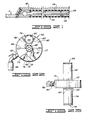
- FIGS. 22 and 23 The third embodiment of the present invention is shown in FIGS. 22 and 23.
- This embodiment defines its flow path insert means with a circular sampling window member 150 having a hollow interior into which-an opening 152 and an opening 154 are defined.
- the opening 152 receives the flow of material and the opening 154 provides an exit for the primary flow of material.
- These openings are connected into the primary conduit through suitable adapter members 156, 158. Because the sampling window member 150 is circular in cross section, there is no need for the adapter elements 156, 158 to provide a circular-to-rectangular transition as in the first two described embodiments.
- the collection member 160 in this embodiment is a vane feeder member having a plurality of vanes 162, 164, 166, 168, 170, 171 affixed to a central shaft 172. Adjacent ones of the vanes define sectors with cross-sectional areas greater than the area of the opening 152 through which the primary flow of material enters the sampling window member 150. This is best shown in FIG. 22 wherein a sector 174 is defined between the vanes 162, 164.
- the sampling window member 150 has a cylindrical peripheral side wall 176 which includes an inner surface 178.
- the vanes 162-171 are suitably sized so that they extend radially outwardly into engagement with the surface 178; however, this engagement is not pressure sealed so that pressure can communicate among the various sectors defined by the vanes whereby there are no pressure differentials across the vanes.
- each vane includes a non-sealing plastic wiper member 179 affixed to the outer end of a principal structural member of the vane. The wiper member non-sealingly sweeps along the surface 178 to shear out a full cross-sectional sample of the flowing material when the shaft 172 is rotated.
- Such shearing out is achieved by rotating the vane feeder member by a suitable means.
- this means includes an air cylinder 180 which drives a ratchet mechanism 182.
- a rack mechanism can be used as would be readily known to the art.
- Other suitable rotational mechanisms can be used.
- the present invention broadly provides a novel and improved sampling apparatus for obtaining representative, full cross-sectional samples of a flowing material, particularly one flowing under a pressure greater or less than atmospheric pressure.
- the present invention is well adapted to carry out the objects and attain the ends and advantages mentioned above as well as those inherent therein. While preferred embodiments of the invention have been described for the purpose of this disclosure, numerous changes in the construction and arrangement of parts can be made by those skilled in the art, which changes are encompassed within the spirit of this invention.
- the invention includes the following:
Landscapes
- Life Sciences & Earth Sciences (AREA)
- Hydrology & Water Resources (AREA)
- Physics & Mathematics (AREA)
- Health & Medical Sciences (AREA)
- Chemical & Material Sciences (AREA)
- Analytical Chemistry (AREA)
- Biochemistry (AREA)
- General Health & Medical Sciences (AREA)
- General Physics & Mathematics (AREA)
- Immunology (AREA)
- Pathology (AREA)
- Sampling And Sample Adjustment (AREA)
Applications Claiming Priority (2)
| Application Number | Priority Date | Filing Date | Title |
|---|---|---|---|
| US06/795,394 US4682506A (en) | 1985-11-06 | 1985-11-06 | Automatic material sampler |
| US795394 | 1997-02-04 |
Publications (3)
| Publication Number | Publication Date |
|---|---|
| EP0222540A2 true EP0222540A2 (de) | 1987-05-20 |
| EP0222540A3 EP0222540A3 (en) | 1988-04-06 |
| EP0222540B1 EP0222540B1 (de) | 1991-09-04 |
Family
ID=25165405
Family Applications (1)
| Application Number | Title | Priority Date | Filing Date |
|---|---|---|---|
| EP86308247A Expired - Lifetime EP0222540B1 (de) | 1985-11-06 | 1986-10-23 | Automatische Materialprobenentnahmevorrichtung |
Country Status (6)
| Country | Link |
|---|---|
| US (1) | US4682506A (de) |
| EP (1) | EP0222540B1 (de) |
| CA (1) | CA1284430C (de) |
| DE (1) | DE3681253D1 (de) |
| ES (1) | ES2023816B3 (de) |
| SG (1) | SG21792G (de) |
Families Citing this family (7)
| Publication number | Priority date | Publication date | Assignee | Title |
|---|---|---|---|---|
| FR2622293B1 (fr) * | 1987-10-21 | 1990-06-22 | Total France | Systeme pour le prelevement dans une enceinte de particules solides en lit fluidise |
| US4858477A (en) * | 1988-06-24 | 1989-08-22 | Halliburton Company | Dry materials sample collector improvements |
| DE19721104A1 (de) | 1997-05-20 | 1998-11-26 | Sympatec Gmbh | Verfahren und Vorrichtung zur Probenahme aus dispersen Stoffströmen |
| US6997346B2 (en) * | 2003-12-08 | 2006-02-14 | Process Control Corporation | Apparatus and method for reducing buildup of particulate matter in particulate-matter-delivery systems |
| US7488141B2 (en) * | 2004-07-14 | 2009-02-10 | Halliburton Energy Services, Inc. | Automated control methods for dry bulk material transfer |
| US9624036B2 (en) | 2012-05-18 | 2017-04-18 | Schlumberger Technology Corporation | System and method for mitigating dust migration at a wellsite |
| CN112834280B (zh) * | 2020-12-31 | 2022-11-01 | 宜春万申制药机械有限公司 | 一种药品在线取样机构 |
Family Cites Families (10)
| Publication number | Priority date | Publication date | Assignee | Title |
|---|---|---|---|---|
| US3005347A (en) * | 1958-08-08 | 1961-10-24 | Int Minerals & Chem Corp | Sampling apparatus |
| US3659461A (en) * | 1970-06-18 | 1972-05-02 | Great Northern Nekoosa Corp | Line sampling device |
| US3690179A (en) * | 1970-09-16 | 1972-09-12 | James F Olson | Rotary samplers |
| US4055088A (en) * | 1976-10-04 | 1977-10-25 | The Dow Chemical Company | Apparatus for sampling dry solids |
| US4082204A (en) * | 1976-10-28 | 1978-04-04 | Marc Savage | Container-dispenser for desiccant material for inclusion in a racket handle |
| US4082004A (en) * | 1977-04-14 | 1978-04-04 | Gustafson, Inc. | Crosscut sampler |
| US4120203A (en) * | 1977-04-14 | 1978-10-17 | Gustafson, Inc. | Crosscut sampler for pneumatic conveying systems |
| US4170900A (en) * | 1978-01-20 | 1979-10-16 | Ozawa Kenneth Y | Rotary sampler for particulate matter |
| US4538472A (en) * | 1983-07-29 | 1985-09-03 | Gustafson, Inc. | Pneumatic crosscut sampler |
| GB2154547B (en) * | 1984-02-24 | 1987-01-21 | George Levey | Liquid sampling device |
-
1985
- 1985-11-06 US US06/795,394 patent/US4682506A/en not_active Expired - Fee Related
-
1986
- 1986-10-23 DE DE8686308247T patent/DE3681253D1/de not_active Expired - Fee Related
- 1986-10-23 ES ES86308247T patent/ES2023816B3/es not_active Expired - Lifetime
- 1986-10-23 EP EP86308247A patent/EP0222540B1/de not_active Expired - Lifetime
- 1986-11-06 CA CA000522368A patent/CA1284430C/en not_active Expired - Lifetime
-
1992
- 1992-03-04 SG SG217/92A patent/SG21792G/en unknown
Also Published As
| Publication number | Publication date |
|---|---|
| ES2023816B3 (es) | 1992-02-16 |
| CA1284430C (en) | 1991-05-28 |
| US4682506A (en) | 1987-07-28 |
| SG21792G (en) | 1992-05-22 |
| EP0222540B1 (de) | 1991-09-04 |
| EP0222540A3 (en) | 1988-04-06 |
| DE3681253D1 (de) | 1991-10-10 |
Similar Documents
| Publication | Publication Date | Title |
|---|---|---|
| US4433587A (en) | Sampler for flowing pressurized dry material | |
| US7743646B2 (en) | Axial flow scan testable filter system | |
| GB1578588A (en) | Pneumatic tube installation for posting samples of fine material | |
| US4479393A (en) | Sampler for slurries | |
| US5433120A (en) | Sampling system for septum closed container | |
| US4682506A (en) | Automatic material sampler | |
| US4144759A (en) | Automatic pulverized coal sampler | |
| US4466761A (en) | Pneumatic-tube conveying installation for samples of fine material | |
| US5154087A (en) | Sampler apparatus | |
| US4283946A (en) | Sampling probe for granular material | |
| US5905213A (en) | Liquid sampler having connecting device | |
| US4082004A (en) | Crosscut sampler | |
| US4562749A (en) | Sampler | |
| US4987785A (en) | Constant volume sampling system | |
| US4682507A (en) | Material sampling apparatus | |
| US4085618A (en) | Composite sampling system and rotatable sampling valve therefor | |
| US4056983A (en) | Flow diversion sampler | |
| US6935198B2 (en) | Sampling apparatus having a linear indexing sample collection station | |
| US4538472A (en) | Pneumatic crosscut sampler | |
| JP2002320438A (ja) | 混捏装置 | |
| US4501296A (en) | Device for charging an electrochemical measuring apparatus | |
| US20090308182A1 (en) | Apparatus for collecting slurry samples from a pipe | |
| FI61360B (fi) | Anordning foer automatisk provtagning ur ett flytande material | |
| US4858477A (en) | Dry materials sample collector improvements | |
| CN207123424U (zh) | 采样器及烟道采样系统 |
Legal Events
| Date | Code | Title | Description |
|---|---|---|---|
| PUAI | Public reference made under article 153(3) epc to a published international application that has entered the european phase |
Free format text: ORIGINAL CODE: 0009012 |
|
| AK | Designated contracting states |
Kind code of ref document: A2 Designated state(s): DE ES FR GB IT NL |
|
| PUAL | Search report despatched |
Free format text: ORIGINAL CODE: 0009013 |
|
| AK | Designated contracting states |
Kind code of ref document: A3 Designated state(s): DE ES FR GB IT NL |
|
| 17P | Request for examination filed |
Effective date: 19880623 |
|
| 17Q | First examination report despatched |
Effective date: 19900124 |
|
| GRAA | (expected) grant |
Free format text: ORIGINAL CODE: 0009210 |
|
| ITF | It: translation for a ep patent filed | ||
| AK | Designated contracting states |
Kind code of ref document: B1 Designated state(s): DE ES FR GB IT NL |
|
| REF | Corresponds to: |
Ref document number: 3681253 Country of ref document: DE Date of ref document: 19911010 |
|
| ET | Fr: translation filed | ||
| REG | Reference to a national code |
Ref country code: ES Ref legal event code: FG2A Ref document number: 2023816 Country of ref document: ES Kind code of ref document: B3 |
|
| PLBE | No opposition filed within time limit |
Free format text: ORIGINAL CODE: 0009261 |
|
| STAA | Information on the status of an ep patent application or granted ep patent |
Free format text: STATUS: NO OPPOSITION FILED WITHIN TIME LIMIT |
|
| 26N | No opposition filed | ||
| PGFP | Annual fee paid to national office [announced via postgrant information from national office to epo] |
Ref country code: ES Payment date: 19941031 Year of fee payment: 9 |
|
| PG25 | Lapsed in a contracting state [announced via postgrant information from national office to epo] |
Ref country code: ES Free format text: LAPSE BECAUSE OF THE APPLICANT RENOUNCES Effective date: 19951024 |
|
| PGFP | Annual fee paid to national office [announced via postgrant information from national office to epo] |
Ref country code: FR Payment date: 19961009 Year of fee payment: 11 |
|
| PGFP | Annual fee paid to national office [announced via postgrant information from national office to epo] |
Ref country code: GB Payment date: 19961014 Year of fee payment: 11 |
|
| PGFP | Annual fee paid to national office [announced via postgrant information from national office to epo] |
Ref country code: NL Payment date: 19961029 Year of fee payment: 11 |
|
| PGFP | Annual fee paid to national office [announced via postgrant information from national office to epo] |
Ref country code: DE Payment date: 19961104 Year of fee payment: 11 |
|
| PG25 | Lapsed in a contracting state [announced via postgrant information from national office to epo] |
Ref country code: GB Free format text: LAPSE BECAUSE OF NON-PAYMENT OF DUE FEES Effective date: 19971023 |
|
| PG25 | Lapsed in a contracting state [announced via postgrant information from national office to epo] |
Ref country code: FR Free format text: THE PATENT HAS BEEN ANNULLED BY A DECISION OF A NATIONAL AUTHORITY Effective date: 19971031 |
|
| PG25 | Lapsed in a contracting state [announced via postgrant information from national office to epo] |
Ref country code: NL Free format text: LAPSE BECAUSE OF NON-PAYMENT OF DUE FEES Effective date: 19980501 |
|
| GBPC | Gb: european patent ceased through non-payment of renewal fee |
Effective date: 19971023 |
|
| NLV4 | Nl: lapsed or anulled due to non-payment of the annual fee |
Effective date: 19980501 |
|
| PG25 | Lapsed in a contracting state [announced via postgrant information from national office to epo] |
Ref country code: DE Free format text: LAPSE BECAUSE OF NON-PAYMENT OF DUE FEES Effective date: 19980701 |
|
| REG | Reference to a national code |
Ref country code: FR Ref legal event code: ST |
|
| REG | Reference to a national code |
Ref country code: ES Ref legal event code: FD2A Effective date: 19991007 |
|
| PG25 | Lapsed in a contracting state [announced via postgrant information from national office to epo] |
Ref country code: IT Free format text: LAPSE BECAUSE OF NON-PAYMENT OF DUE FEES;WARNING: LAPSES OF ITALIAN PATENTS WITH EFFECTIVE DATE BEFORE 2007 MAY HAVE OCCURRED AT ANY TIME BEFORE 2007. THE CORRECT EFFECTIVE DATE MAY BE DIFFERENT FROM THE ONE RECORDED. Effective date: 20051023 |