EP0222402A2 - Cooling air guiding device for an air cooled internal-combustion engine - Google Patents
Cooling air guiding device for an air cooled internal-combustion engine Download PDFInfo
- Publication number
- EP0222402A2 EP0222402A2 EP86115779A EP86115779A EP0222402A2 EP 0222402 A2 EP0222402 A2 EP 0222402A2 EP 86115779 A EP86115779 A EP 86115779A EP 86115779 A EP86115779 A EP 86115779A EP 0222402 A2 EP0222402 A2 EP 0222402A2
- Authority
- EP
- European Patent Office
- Prior art keywords
- combustion engine
- internal combustion
- row
- cooling air
- cylinders
- Prior art date
- Legal status (The legal status is an assumption and is not a legal conclusion. Google has not performed a legal analysis and makes no representation as to the accuracy of the status listed.)
- Granted
Links
Images

Classifications
-
- F—MECHANICAL ENGINEERING; LIGHTING; HEATING; WEAPONS; BLASTING
- F01—MACHINES OR ENGINES IN GENERAL; ENGINE PLANTS IN GENERAL; STEAM ENGINES
- F01P—COOLING OF MACHINES OR ENGINES IN GENERAL; COOLING OF INTERNAL-COMBUSTION ENGINES
- F01P1/00—Air cooling
- F01P1/02—Arrangements for cooling cylinders or cylinder heads, e.g. ducting cooling-air from its pressure source to cylinders or along cylinders
-
- F—MECHANICAL ENGINEERING; LIGHTING; HEATING; WEAPONS; BLASTING
- F01—MACHINES OR ENGINES IN GENERAL; ENGINE PLANTS IN GENERAL; STEAM ENGINES
- F01P—COOLING OF MACHINES OR ENGINES IN GENERAL; COOLING OF INTERNAL-COMBUSTION ENGINES
- F01P5/00—Pumping cooling-air or liquid coolants
- F01P5/02—Pumping cooling-air; Arrangements of cooling-air pumps, e.g. fans or blowers
- F01P5/06—Guiding or ducting air to, or from, ducted fans
-
- F—MECHANICAL ENGINEERING; LIGHTING; HEATING; WEAPONS; BLASTING
- F02—COMBUSTION ENGINES; HOT-GAS OR COMBUSTION-PRODUCT ENGINE PLANTS
- F02B—INTERNAL-COMBUSTION PISTON ENGINES; COMBUSTION ENGINES IN GENERAL
- F02B75/00—Other engines
- F02B75/16—Engines characterised by number of cylinders, e.g. single-cylinder engines
- F02B75/18—Multi-cylinder engines
- F02B75/20—Multi-cylinder engines with cylinders all in one line
Definitions
- the invention relates to an air-cooled internal combustion engine with a cooling air duct according to the preamble of claim 1.
- An air-cooled internal combustion engine of this type is known from DE-PS 11 35 711.
- the fan arranged to generate the cooling air flow is fastened lying next to the first cylinder in such a way that the incoming cooling air flow enters the cooling air duct next to the first cylinder.
- the cooling fins of the cylinder heads are arranged transversely to the longitudinal center axis of the row of cylinders, since the cooling air - also in the region of the first cylinder - flows through the row of cylinders essentially transversely to the longitudinal center axis.
- the lateral offset of the blower to the cylinder head row (distance from the longitudinal center axis - blower to the longitudinal center axis - cylinder head row) essentially determines the installation width of an air-cooled engine. This offset cannot be reduced arbitrarily, since in particular the transverse cooling fins of the first cylinder adjacent to the fan block the fan outlet and would thus reduce the efficiency.
- the invention has for its object to design the cooling air duct of an air-cooled internal combustion engine such that the lateral offset of the fan to the longitudinal center axis of the row of cylinders can be kept as low as possible.
- this object is achieved by the characterizing features of the first claim. Due to the cooling fins oriented in the overlap area of the fan and the row of cylinders, approximately in the flow direction of the incoming cooling air flow, a hindrance to the incoming cooling air is largely avoided.
- the cooling fins arranged according to the invention deflect the cooling air from its inflow direction in the transverse direction within the first cylinder head.
- the cooling fins are preferably aligned approximately parallel to the longitudinal center axis of the row of cylinders.
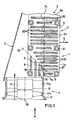
- the section shown in FIG. 1 shows a plurality of cylinders 1, 2, 3, which are arranged in a row and carry a block cylinder head.
- the block cylinder head is fastened to the latter by means of fastening screws which are screwed into the cylinder blocks by cylinder head pipes 21.
- a blower 4 in the longitudinal direction of the cylinder bank 5 in the area of the first cylinder 1, which blower is designed as an axial blower in the exemplary embodiment shown.
- the fan 4 has a housing jacket 17, in which a stator 17a is arranged, which holds the hub of the impeller 17b centrally.
- the fan 4 generates a cooling air flow K which is directed essentially parallel to the longitudinal central axis 14 of the cylinder bank 5.
- a cooling air guide 7 adjoins the fan 4 arranged in front of the cylinder bank 5 and redirects the cooling air flow K entering in the longitudinal direction of the cylinder bank 5 such that the cooling air essentially flows through the cylinder bank and exits in the direction of arrow 6.
- the cooling fins 20 of the cylinder heads 1a, 2a, 3a are arranged transversely to the row of cylinders 5 in accordance with the flow in the direction of the arrow 6 and are essentially at right angles to the longitudinal central axis 14.
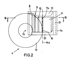
- the blower 4 is arranged in such a way that part of the cooling air flow K in the longitudinal direction of the cylinder bank 5 on the first Zy linderkopf 1a hits.
- the blower 4 is arranged in such a way that its longitudinal central axis 15 lies parallel to the longitudinal central axis 14 of the cylinder bank 5, an outer surface line 16 of the housing shell 17 lying in the longitudinal center plane 14a (FIG. 2) of the cylinder bank 5.
- the cross section 12 of the axial fan 4 overlaps - seen in the direction of arrow A - partially with the first cylinder 1 or its cylinder head 1a (FIG. 2).
- the cooling fins 8, 9, 10 of the cylinder head 1 a lying in the overlap region of the blower 4 with the first cylinder 1 are aligned according to the invention approximately in the flow direction of the incoming cooling air flow K. They are preferably parallel to the longitudinal center axis 14 of the row of cylinders 5. It can also be expedient to arrange the cooling fins at an angle to the longitudinal center axis 14, this angle being an obtuse angle to the blower 14 or an acute angle.
- the cooling fin 8 directly adjacent to the cooling air guide 7 is longest, while the cooling fin 9, 10 lying between the cooling fin 8 and the longitudinal central axis 14 is designed with decreasing length toward the longitudinal central axis 14.
- the cooling fins 8, 9, 10 preferably extend up to approximately a straight line 19 which forms an angle 18 which is open to the blower 4 with the longitudinal center axis 14.
- This angle can be an acute or an obtuse angle, with an obtuse angle being preferred.
- the cooling fins 8, 9, 10 in the exemplary embodiment according to FIG. 1 are distributed over approximately a quarter of the area of the cylinder head 1 a and aligned in the flow direction of the incoming cooling air K parallel to the longitudinal central axis 14, while the remaining cooling fins pen 20 are distributed over the remaining surface of the cylinder head 1 a and lie transversely to the cooling air flow K (at right angles to the longitudinal central axis 14).
- a cylinder head row is shown as a preferred embodiment, in which only the first cylinder head 1a has some cooling fins 8, 9, 10 aligned in the flow direction of the incoming cooling air. It may be advantageous to also provide the following cylinder heads with one or more cooling fins which are aligned in the longitudinal direction of the row of cylinder heads.
- the cooling fins 8, 9, 10 are arranged separately from the cooling fins 20 lying transversely to the longitudinal center axis 14. This separation can be provided in such a way that a type of channel is formed between the ribs oriented in the longitudinal direction and the ribs oriented in the transverse direction.
- the cooling fins 8.1, 9.1, 10.1 aligned in the longitudinal direction of the cylinder row in such a way that they each merge into a transverse cooling fin 20.1 (FIGS. 3 and 4).
- the transitions are designed with large deflection radii R, which contribute to low-resistance air deflection.
- 4 shows a design in which the transition is formed from a straight fin sections 30, which, with appropriately selected transition radii, lie on the cooling fin 8.1 or 9.1 or 10.1 lying parallel to the longitudinal central axis 14 and the associated one lying at right angles to the longitudinal central axis 14 Cooling fin 20.1 connects.
- the cooling fins 8.1, 9.1, 10.1 and 20.1 correspond to the longitudinal Extension of the rib sections 30 is shorter.
- the rib sections 30 lie or at an angle of approximately 45 ° to the longitudinal central axis.
- the foremost, transversely positioned cooling fin 11 of the cylinder head 1 a, which is adjacent to the blower 4, is L-shaped in plan view, its smaller leg 11 a lying in the plane 14 a (FIG. 2) of the longitudinal central axis 14 of the cylinder bank 5.
- Both the transverse cooling fins 20 and the longitudinally oriented cooling fins 8, 9, 10 and 11a are designed as load-bearing elements for supporting the combustion chamber floor 22 against the valve or / and camshaft trough 13.
Abstract
Description
Die Erfindung betrifft eine luftgekühlte Brennkraftmaschine mit einer Kühlluftführung gemäß dem Oberbegriff des Anspruchs 1.The invention relates to an air-cooled internal combustion engine with a cooling air duct according to the preamble of claim 1.
Eine luftgekühlte Brennkraftmaschine dieser Art ist aus der DE-PS 11 35 711 bekannt. Das zur Erzeugung des Kühlluftstroms angeordnete Gebläse ist neben dem ersten Zylinder liegend so befestigt, daß der eintretende Kühlluftstrom neben dem ersten Zylinder in die Kühlluftführung eintritt. Die Kühlrippen der Zylinderköpfe sind dabei quer zur Längsmittelachse der Zylinderreihe angeordnet, da die Kühlluft - auch im Bereich des ersten Zylinders - im wesentlichen quer zur Längsmittelachse die Zylinderreihe durchströmt.An air-cooled internal combustion engine of this type is known from DE-PS 11 35 711. The fan arranged to generate the cooling air flow is fastened lying next to the first cylinder in such a way that the incoming cooling air flow enters the cooling air duct next to the first cylinder. The cooling fins of the cylinder heads are arranged transversely to the longitudinal center axis of the row of cylinders, since the cooling air - also in the region of the first cylinder - flows through the row of cylinders essentially transversely to the longitudinal center axis.
Der seitliche Versatz des Gebläses zur Zylinderkopfreihe, (Abstand Längsmittelachse - Gebläse zur Längsmittelachse - Zylinderkopfreihe) bestimmt wesentlich die Einbaubreite eines luftgekühlten Motors. Dieser Versatz kann nicht beliebig verringert werden, da insbesondere die quergestellten Kühlrippen des dem Gebläse benachbarten ersten Zylinders den Gebläseaustritt versperren und so den Wirkungsgrad verringern würde.The lateral offset of the blower to the cylinder head row (distance from the longitudinal center axis - blower to the longitudinal center axis - cylinder head row) essentially determines the installation width of an air-cooled engine. This offset cannot be reduced arbitrarily, since in particular the transverse cooling fins of the first cylinder adjacent to the fan block the fan outlet and would thus reduce the efficiency.
Der Erfindung liegt die Aufgabe zugrunde, die Kühlluftführung einer luftgekühlten Brennkraftmaschine derart auszubilden, daß der seitliche Versatz des Gebläses zur Längsmittelachse der Zylinderreihe möglichst gering gehalten werden kann.The invention has for its object to design the cooling air duct of an air-cooled internal combustion engine such that the lateral offset of the fan to the longitudinal center axis of the row of cylinders can be kept as low as possible.
Diese Aufgabe wird erfindungsgemäß durch die kennzeichnenden Merkmale des ersten Anspruchs gelöst. Aufgrund der im Überdeckungsbereich des Gebläses und der Zylinderreihe etwa in Strömungsrichtung des einströmenden Kühlluftstroms ausgerichteten Kühlrippen wird eine Behinderung der einströmenden Kühlluft weitgehend vermieden. Die erfindungsgemäß angeordneten Kühlrippen lenken innerhalb des ersten Zylinderkopfes die Kühlluft von ihrer Einströmrichtung in Querrichtung um. Dabei sind die Kühlrippen vorzugsweise etwa parallel zur Längsmittelachse der Zylinderreihe ausgerichtet. Durch diese Maßnahmen kann die Einbaulänge und Einbaubreite eines luftgekühlten Motors erheblich reduziert werden.According to the invention, this object is achieved by the characterizing features of the first claim. Due to the cooling fins oriented in the overlap area of the fan and the row of cylinders, approximately in the flow direction of the incoming cooling air flow, a hindrance to the incoming cooling air is largely avoided. The cooling fins arranged according to the invention deflect the cooling air from its inflow direction in the transverse direction within the first cylinder head. The cooling fins are preferably aligned approximately parallel to the longitudinal center axis of the row of cylinders. These measures can significantly reduce the installation length and width of an air-cooled motor.
Weitere Merkmale der Erfindung ergeben sich aus den weiteren Ansprüchen, der Beschreibung und den Zeichnungen, die Ausführungsbeispiele der Erfindung zeigen und im folgenden näher beschrieben sind. Es zeigen:
- Fig. 1 in Draufsicht einen Schnitt durch die Kühlluftführung einer Brennkraftmaschine in Höhe der Zylinderköpfe längs der Linie B-B in Fig. 2,
- Fig. 2 eine Ansicht gemäß Pfeil A aus Fig. 1 auf das Kühlgebläse mit dahinter angeordneten Zylinderköpfen,
- Fig. 3 eine Draufsicht auf einen Zylinderkopf mit einer Kühlrippenanordnung anderer Ausführung,
- Fig. 4 eine Draufsicht auf einen Zylinderkopf mit einer weiteren Ausführungsmöglichkeit der Kühlrippen
- 1 is a plan view of a section through the cooling air duct of an internal combustion engine at the level of the cylinder heads along the line BB in FIG. 2,
- 2 shows a view according to arrow A from FIG. 1 of the cooling fan with cylinder heads arranged behind it,
- 3 is a plan view of a cylinder head with a cooling fin arrangement of another design,
- Fig. 4 is a plan view of a cylinder head with a further embodiment of the cooling fins
Der in Fig. 1 dargestellte Schnitt zeigt mehrere in einer Reihe hintereinander angeordnete Zylinder 1,2,3, die einen Blockzylinderkopf tragen. Der Blockzylinderkopf ist mittels Befestigungsschrauben, die durch Zylinderkopfpfeifen 21 in die Zylinderblöcke eingeschraubt sind, an diesem befestigt. Zur Kühlung liegt in Längsrichtung der Zylinderreihe 5 im Bereich des ersten Zylinders 1 ein Gebläse 4, das im gezeigten Ausführungsbeispiel als Axialgebläse ausgeführt ist. Das Gebläse 4 hat einen Gehäusemantel 17, in dem ein Leitrad 17a angeordnet ist, das die Nabe des Gebläserades 17b zentrisch hält. Das Gebläse 4 erzeugt einen Kühlluftstrom K, der im wesentlichen parallel zur Längsmittelachse 14 der Zylinderreihe 5 gerichtet ist. An das vor der Zylinderreihe 5 angeordnete Gebläse 4 schließt eine Kühlluftführung 7 an, die den in Längsrichtung der Zylinderreihe 5 eintretenden Kühlluftstrom K derart umleitet, daß die Kühlluft im wesentlichen quer zur Zylinderreihe diese durchströmt und in Pfeilrichtung 6 austritt. Die Kühlrippen 20 der Zylinderköpfe 1a,2a,3a sind - gemäß der Strömung in Pfeilrichtung 6 - quer zur Zylinderreihe 5 angeordnet und liegen im wesentlichen rechtwinklig zur Längsmittelachse 14.The section shown in FIG. 1 shows a plurality of
Zur Reduzierung der Einbaulänge sowie der Einbaubreite eines luftgekühlten Motors ist nunmehr vorgesehen, das Gebläse 4 derart anzuordnen, daß ein Teil des Kühlluftstroms K in Längsrichtung der Zylinderreihe 5 auf den ersten Zy linderkopf 1a auftrifft. Hierzu ist das Gebläse 4 derart angeordnet, daß seine Längsmittelachse 15 parallel zur Längsmittelachse 14 der Zylinderreihe 5 liegt, wobei eine äußere Mantellinie 16 des Gehäusemantels 17 in der Längsmittelebene 14a (Fig. 2) der Zylinderreihe 5 liegt. Der Querschnitt 12 des Axialgebläses 4 überdeckt sich dabei - in Pfeilrichtung A gesehen - teilweise mit dem ersten Zylinder 1 bzw. dessen Zylinderkopf 1a (Fig. 2). Die im Überdeckungsbereich des Gebläses 4 mit dem ersten Zylinder 1 liegenden Kühlrippen 8,9,10 des Zylinderkopfes 1a sind gemäß der Erfindung etwa in Strömungsrichtung des einströmenden Kühlluftstroms K ausgerichtet. Sie liegen vorzugsweise parallel zur Längsmittelachse 14 der Zylinderreihe 5. Es kann auch zweckmäßig sein, die Kühlrippen in einem Winkel zur Längsmittelachse 14 anzuordnen, wobei dieser Winkel ein zum Gebläse 14 offener, stumpfer Winkel oder ein spitzer Winkel sein kann. Die der Kühlluftführung 7 unmittelbar benachbarte Kühlrippe 8 ist am längsten ausgebildet, während die zwischen der Kühlrippe 8 und der Längsmittelachse 14 liegenden Kühlrippe 9,10 zur Längsmittelachse 14 hin mit abnehmender Länge ausgebildet sind. Hierbei erstrecken sich die Kühlrippen 8,9,10 vorzugsweise bis etwa an eine Gerade 19, die mit der Längsmittelachse 14 einen zum Gebläse 4 offenen Winkel 18 bildet. Dieser Winkel kann ein spitzer oder ein stumpfer Winkel sein, wobei ein stumpfer Winkel vorgezogen wird.To reduce the installation length and the installation width of an air-cooled engine, it is now provided to arrange the blower 4 in such a way that part of the cooling air flow K in the longitudinal direction of the
In Draufsicht gesehen sind die Kühlrippen 8,9,10 im Ausführungsbeispiel nach Fig. 1 etwa über ein Viertel der Fläche des Zylinderkopfes 1a verteilt und in Strömungsrichtung der einströmenden Kühlluft K parallel zur Längsmittelachse 14 ausgerichtet, während die übrigen Kühlrip pen 20 über die restliche Fläche des Zylinderkopfes 1a verteilt sind und quer zum Kühlluftstrom K (im rechten Winkel zur Längsmittelachse 14) liegen.Viewed in plan view, the cooling fins 8, 9, 10 in the exemplary embodiment according to FIG. 1 are distributed over approximately a quarter of the area of the cylinder head 1 a and aligned in the flow direction of the incoming cooling air K parallel to the longitudinal
Im dargestellten Ausführungsbeispiel ist als bevorzugte Ausführungsform eine Zylinderkopfreihe gezeigt, bei der nur der erste Zylinderkopf 1a einige in Strömungsrichtung der einströmenden Kühlluft ausgerichtete Kühlrippen 8,9,10 aufweist. Es kann vorteilhaft sein, auch die folgenden Zylinkerköpfe mit einer oder mehreren Kühlrippen zu versehen, die in Längsrichtung der Zylinderkopfreihe ausgerichtet sind.In the exemplary embodiment shown, a cylinder head row is shown as a preferred embodiment, in which only the first cylinder head 1a has some
Die Kühlrippen 8,9,10 sind gemäß Fig. 1 getrennt von dem quer zur Längsmittelachse 14 liegenden Kühlrippen 20 angeordnet. Diese Trennung kann so vorgesehen sein, daß eine Art Kanal zwischen den in Längsrichtung und den in Querrichtung ausgerichteten Rippen geibldet ist.1, the
Es kann zur widerstandsarmen Kühlluftumlenkung vorteilhaft sein, einige oder alle in Längsrichtung der Zylinderreihe ausgerichteten Kühlrippen 8.1, 9.1, 10.1 so auszubilden, daß sie jeweils in eine quergestellte Kühlrippe 20.1 übergehen (Fig. 3 und 4). Die Übergänge sind dabei mit großen Umlenkradien R ausgebildet, die zur widerstandsarmen Luftumlenkung beitragen. In Fig. 4 ist eine Ausbildung gezeigt, bei der der Übergang aus einem geraden Rippenteilstücke 30 gebildet ist, das mit entsprechend gewählten Übergangsradien an die parallel zur Längsmittelachse 14 liegende Kühlrippe 8.1 bzw. 9.1 bzw. 10.1 und die zugeordnete, rechtwinklig zur Längsmittelachse 14 liegende Kühlrippe 20.1 anschließt. In dieser Ausführungsform sind die Kühlrippen 8.1, 9.1, 10.1 und 20.1 entsprechend der Längs erstreckung der Rippenteilstücke 30 kürzer ausgebildet. Die Rippenteilstücke 30 liegen bzw. unter einem Winkel von etwa 45° zur Längsmittelachse.For low-resistance cooling air deflection, it can be advantageous to design some or all of the cooling fins 8.1, 9.1, 10.1 aligned in the longitudinal direction of the cylinder row in such a way that they each merge into a transverse cooling fin 20.1 (FIGS. 3 and 4). The transitions are designed with large deflection radii R, which contribute to low-resistance air deflection. 4 shows a design in which the transition is formed from a
Die vorderste, dem Gebläse 4 benachbarte, quergestellte Kühlrippe 11 des Zylinderkopfes 1a ist in Draufsicht L-förmig ausgebildet, wobei ihr kleinerer Schenkel 11a in der Ebene 14a (Fig. 2) der Längsmittelachse 14 der Zylinderreihe 5 liegt.The foremost, transversely positioned
Sowohl die quergestellten Kühlrippen 20 wie die in Längsrichtung ausgerichteten Kühlrippen 8,9,10 und 11a sind als tragende Elemente zur Abstützung des Brennraumbodens 22 gegen den Ventil- oder/und Nockenwellentrog 13 ausgebildet.Both the
Claims (12)
dadurch gekennzeichnet, daß das Gebläse (4) derart benachbart zum ersten Zylinder (1) angeordnet ist, daß ein Teil seines Kühlluftstroms (K) in Längsrichtung der Zylinderreihe (5) auf den ersten Zylinder (1) auftrifft und daß zumindest einige Kühlrippen (8,9,10) des Zylinderkopfes (1a) zumindest des ersten Zylinders (1) etwa in Strömungsrichtung des Kühlluftstroms (K) ausgerichtet sind.1. Air-cooled internal combustion engine with a plurality of cylinders (1, 2, 3) arranged in a row and a blower (4) arranged in the region of the first cylinder, which generates a cooling air flow (K) directed in the longitudinal direction of the row of cylinders (5), which by means of a Air duct (7) is deflected and largely guided across the row of cylinders (5),
characterized in that the fan (4) is arranged adjacent to the first cylinder (1) in such a way that part of its cooling air flow (K) strikes the first cylinder (1) in the longitudinal direction of the row of cylinders (5) and that at least some cooling fins (8 , 9, 10) of the cylinder head (1a) of at least the first cylinder (1) are oriented approximately in the flow direction of the cooling air flow (K).
dadurch gekennzeichnet, daß die Kühlrippen (8,9,10) etwa parallel zur Längsmittelachse (14) der Zylinderreihe (5) ausgerichtet sind.2. Internal combustion engine according to claim 1,
characterized in that the cooling fins (8, 9, 10) are aligned approximately parallel to the longitudinal central axis (14) of the row of cylinders (5).
dadurch gekennzeichnet, daß sich der Querschnitt (12) des Axialgebläses (4) teilweise mit dem ersten Zylinder (1) der Zylinderreihe (5) überdeckt (Fig. 2).3. Internal combustion engine according to claim 1 with an axial fan (4),
characterized in that the cross-section (12) of the axial fan (4) partially overlaps with the first cylinder (1) of the row of cylinders (5) (Fig. 2).
dadurch gekennzeichnet, daß eine Mantellinie (16) der äußeren Gehäusemantelfläche (17) des Axialgebläses (4) gleichachsig zur Längsmittelachse (14) der Zylinderreihe (5) liegt.4. Internal combustion engine according to one of claims 1 to 3, with an axial fan (4) whose longitudinal central axis (15) is parallel to the longitudinal central axis (14) of the row of cylinders (5),
characterized in that a surface line (16) of the outer housing surface (17) of the axial fan (4) lies coaxially with the longitudinal center axis (14) of the row of cylinders (5).
dadurch gekennzeichnet, daß die in Strömungsrichtung des Kühlluftstroms (K) ausgerichteten Kühlrippen (8,9,10) etwa auf einer Geraden (19) enden, die mit der Längsmittelachse (14) einen zum Gebläse (4) offenen, stumpfen Winkel (18) bildet.5. Internal combustion engine according to one of claims 1 to 4,
characterized in that the cooling fins (8, 9, 10) oriented in the flow direction of the cooling air flow (K) end approximately on a straight line (19) which, with the longitudinal central axis (14), forms an obtuse angle (18) open to the blower (4) forms.
dadurch gekennzeichnet, daß die der Kühlluftführung (7) benachbarte, in Strömungsrichtung der einströmenden Kühlluft (K) ausgerichtete Kühlrippe (8) die längste Ersteckung hat.6. Internal combustion engine according to claim 5,
characterized in that the cooling rib (8) adjacent to the cooling air guide (7) and oriented in the flow direction of the incoming cooling air (K) has the longest extension.
dadurch gekennzeichnet, daß die vorderste quer zur Zylinderkopfreihe (5) liegende Kühlrippe (11) in Draufsicht L-förmig ausgebildet und mit ihrem kleineren Schenkel (11a) in der Längsmittelebene (14a) (Fig. 2) der Längsmittelachse (15) der Zylinderreihe (5) liegt.7. Internal combustion engine according to one of claims 1 to 6,
characterized in that the foremost cooling fin (11) lying transversely to the cylinder head row (5) is L-shaped in plan view and with its smaller leg (11a) in the longitudinal center plane (14a) (Fig. 2) of the longitudinal center axis (15) of the row of cylinders ( 5) lies.
dadurch gekennzeichnet, daß zumindest einige der in Strömungsrichtung des Kühlluftstroms (K) ausgerichteten Kühlrippen (8,9,10 bzw. 8.1, 9.1, 10.1) in die quer zur Längsmittelachse (14) liegenden Rippen (20.1) übergehen, wobei die Übergänge zur widerstandsarmen Luftumlenkung entsprechend große Umlenkradien aufweisen.8. Internal combustion engine according to one of claims 1 to 6,
characterized in that at least some of the cooling fins (8, 9, 10, 8.1, 9.1, 10.1) oriented in the flow direction of the cooling air flow (K) merge into the fins (20.1) lying transversely to the longitudinal central axis (14), the transitions to the low-resistance Air deflection have correspondingly large deflection radii.
dadurch gekennzeichnet, daß zumindest einige der quer zur Längsmittelachse (14) der Zylinderreihe (5) angeordneten Kühlrippen (20) getrennt von den in Längsrichtung der Längsmittelachse (14) ausgerichteten Kühlrippen (8,9,10) angeordnet sind.9. Internal combustion engine according to one of claims 1 to 6,
characterized in that at least some of the cooling fins (20) arranged transversely to the longitudinal central axis (14) of the row of cylinders (5) are arranged separately from the cooling fins (8,9,10) oriented in the longitudinal direction of the longitudinal central axis (14).
dadurch gekennzeichnet, daß ausschließlich einige Kühlrippen(8,9,10) des ersten Zylinderkopfes (1a) in Strömungsrichtung des einströmenden Kühlluftstroms (K) ausgerichtet sind.10. Internal combustion engine according to one of claims 1 to 9,
characterized in that only a few cooling fins (8, 9, 10) of the first cylinder head (1a) are oriented in the direction of flow of the incoming cooling air flow (K).
dadurch gekennzeichnet, daß alle in Strömungsrichtung des Kühlluftstroms (K) ausgerichtete Rippen (8.1,9.1,10.1) mit je einer quer zur Längsmittelachse (14) liegenden Rippe (20) verbunden sind.11. Internal combustion engine according to claim 8,
characterized in that all the ribs (8.1,9.1,10.1) aligned in the flow direction of the cooling air flow (K) are each connected to a rib (20) lying transversely to the longitudinal central axis (14).
dadurch gekennzeichnet, daß jede zweite quer zur Längsmittelachse (14) liegende Rippe (20) mit einer in Strömungsrichtung des Kühlluftstroms (K) ausgerichteten Rippe (8.1, 9.1, 10.1) verbunden ist.12. Internal combustion engine according to claim 8 or 11,
characterized in that every second rib (20) lying transversely to the longitudinal central axis (14) is connected to a rib (8.1, 9.1, 10.1) oriented in the direction of flow of the cooling air flow (K).
Priority Applications (1)
| Application Number | Priority Date | Filing Date | Title |
|---|---|---|---|
| AT86115779T ATE50828T1 (en) | 1985-11-15 | 1986-11-13 | COOLING AIR GUIDANCE IN AN AIR-COOLED INTERNAL ENGINE. |
Applications Claiming Priority (2)
| Application Number | Priority Date | Filing Date | Title |
|---|---|---|---|
| DE19853540489 DE3540489A1 (en) | 1985-11-15 | 1985-11-15 | COOLING AIR GUIDE IN AN AIR COOLED INTERNAL COMBUSTION ENGINE |
| DE3540489 | 1985-11-15 |
Publications (3)
| Publication Number | Publication Date |
|---|---|
| EP0222402A2 true EP0222402A2 (en) | 1987-05-20 |
| EP0222402A3 EP0222402A3 (en) | 1988-07-27 |
| EP0222402B1 EP0222402B1 (en) | 1990-03-07 |
Family
ID=6286031
Family Applications (1)
| Application Number | Title | Priority Date | Filing Date |
|---|---|---|---|
| EP86115779A Expired - Lifetime EP0222402B1 (en) | 1985-11-15 | 1986-11-13 | Cooling air guiding device for an air cooled internal-combustion engine |
Country Status (6)
| Country | Link |
|---|---|
| US (1) | US4747374A (en) |
| EP (1) | EP0222402B1 (en) |
| JP (1) | JPS62135608A (en) |
| AT (1) | ATE50828T1 (en) |
| DE (2) | DE3540489A1 (en) |
| ES (1) | ES2014223B3 (en) |
Cited By (1)
| Publication number | Priority date | Publication date | Assignee | Title |
|---|---|---|---|---|
| WO2009010218A1 (en) * | 2007-07-16 | 2009-01-22 | Knorr-Bremse Systeme für Nutzfahrzeuge GmbH | Y-shaped cooling fin arrangement |
Families Citing this family (1)
| Publication number | Priority date | Publication date | Assignee | Title |
|---|---|---|---|---|
| US7179402B2 (en) * | 2004-02-02 | 2007-02-20 | General Electric Company | Phosphors containing phosphate and/or borate of metals of group IIIA, group IVA, and lanthanide series, and light sources incorporating the same |
Citations (3)
| Publication number | Priority date | Publication date | Assignee | Title |
|---|---|---|---|---|
| NL11851C (en) * | 1900-01-01 | |||
| DE880823C (en) * | 1949-11-24 | 1953-06-25 | Schweizerische Lokomotiv | Air-cooled internal combustion engine |
| DE3540488A1 (en) * | 1985-11-15 | 1987-05-21 | Kloeckner Humboldt Deutz Ag | Cooling air duct in an air-cooled internal combustion engine |
Family Cites Families (6)
| Publication number | Priority date | Publication date | Assignee | Title |
|---|---|---|---|---|
| CA504329A (en) * | 1954-07-13 | Sonderegger Konrad | Oil-cooler arrangement in air-cooled internal combustion engines | |
| US1683602A (en) * | 1921-04-11 | 1928-09-11 | Ind Res Corp | Engine-cooling system |
| DE585221C (en) * | 1931-02-19 | 1933-09-30 | Ludwig Baersch Dipl Ing | Air-cooled internal combustion engine |
| US2289959A (en) * | 1940-07-17 | 1942-07-14 | Fairchild Engine & Airplane | Cooling system for engines |
| FR917119A (en) * | 1944-11-13 | 1946-12-26 | Schweizerische Lokomotiv | Compressor-powered, air-cooled combustion engine |
| JPS5311248A (en) * | 1976-07-19 | 1978-02-01 | Kawasaki Heavy Ind Ltd | Engine cover |
-
1985
- 1985-11-15 DE DE19853540489 patent/DE3540489A1/en not_active Withdrawn
-
1986
- 1986-11-12 US US06/930,140 patent/US4747374A/en not_active Expired - Fee Related
- 1986-11-13 JP JP61270850A patent/JPS62135608A/en active Pending
- 1986-11-13 DE DE8686115779T patent/DE3669345D1/en not_active Expired - Fee Related
- 1986-11-13 ES ES86115779T patent/ES2014223B3/en not_active Expired - Lifetime
- 1986-11-13 AT AT86115779T patent/ATE50828T1/en not_active IP Right Cessation
- 1986-11-13 EP EP86115779A patent/EP0222402B1/en not_active Expired - Lifetime
Patent Citations (3)
| Publication number | Priority date | Publication date | Assignee | Title |
|---|---|---|---|---|
| NL11851C (en) * | 1900-01-01 | |||
| DE880823C (en) * | 1949-11-24 | 1953-06-25 | Schweizerische Lokomotiv | Air-cooled internal combustion engine |
| DE3540488A1 (en) * | 1985-11-15 | 1987-05-21 | Kloeckner Humboldt Deutz Ag | Cooling air duct in an air-cooled internal combustion engine |
Cited By (1)
| Publication number | Priority date | Publication date | Assignee | Title |
|---|---|---|---|---|
| WO2009010218A1 (en) * | 2007-07-16 | 2009-01-22 | Knorr-Bremse Systeme für Nutzfahrzeuge GmbH | Y-shaped cooling fin arrangement |
Also Published As
| Publication number | Publication date |
|---|---|
| EP0222402B1 (en) | 1990-03-07 |
| ATE50828T1 (en) | 1990-03-15 |
| DE3540489A1 (en) | 1987-05-21 |
| ES2014223B3 (en) | 1990-07-01 |
| US4747374A (en) | 1988-05-31 |
| EP0222402A3 (en) | 1988-07-27 |
| DE3669345D1 (en) | 1990-04-12 |
| JPS62135608A (en) | 1987-06-18 |
Similar Documents
| Publication | Publication Date | Title |
|---|---|---|
| DE2417925A1 (en) | COMBUSTION ENGINE | |
| DE3139309C2 (en) | Intake system for an internal combustion engine | |
| DE102006000337A1 (en) | Air intake device | |
| EP0268988B1 (en) | Diesel engine | |
| DE10064264B4 (en) | Arrangement for cooling a component | |
| EP1516113A1 (en) | Cooled cylinder head for a reciprocating engine | |
| AT402431B (en) | TWO-STROKE INTERNAL COMBUSTION ENGINE | |
| DE102010011726A1 (en) | Two-stroke engine and engine with this two-stroke engine | |
| EP0222402B1 (en) | Cooling air guiding device for an air cooled internal-combustion engine | |
| EP0204687B1 (en) | Two-stroke internal-combustion engine | |
| DE102004060187B4 (en) | Variable intake system of a vehicle | |
| DE3905254A1 (en) | Cooling device for fuel injection valves of an internal combustion engine | |
| DE3540488C2 (en) | ||
| DE2017877A1 (en) | Cylinder head | |
| DE1296460B (en) | Cylinder head for internal combustion engines with two inlet and two outlet valves per cylinder | |
| DE2227120C2 (en) | Air-cooled reciprocating internal combustion engine | |
| EP4127483A1 (en) | Jet ventilator for ventilating tunnels, jet ventilator system and method | |
| DE679642C (en) | Multi-cylinder, slot-controlled two-stroke internal combustion engine in an in-line arrangement | |
| DE102017212645B4 (en) | Cylinder head for an internal combustion engine | |
| EP0637680A1 (en) | Liquid cooled multicylinder internal combustion engine | |
| DE3015444A1 (en) | EXHAUST SILENCER | |
| EP0123101B1 (en) | Cylinder head for an air-cooled internal-combustion piston engine | |
| DE3724494A1 (en) | Liquid-cooled cylinder head for an internal combustion engine | |
| AT254621B (en) | Internal combustion engine with rows of cylinders arranged in a V shape | |
| DE975228C (en) | Air-cooled cylinder head for internal combustion engines |
Legal Events
| Date | Code | Title | Description |
|---|---|---|---|
| PUAI | Public reference made under article 153(3) epc to a published international application that has entered the european phase |
Free format text: ORIGINAL CODE: 0009012 |
|
| AK | Designated contracting states |
Kind code of ref document: A2 Designated state(s): AT DE ES FR GB IT |
|
| PUAL | Search report despatched |
Free format text: ORIGINAL CODE: 0009013 |
|
| AK | Designated contracting states |
Kind code of ref document: A3 Designated state(s): AT DE ES FR GB IT |
|
| 17P | Request for examination filed |
Effective date: 19880610 |
|
| 17Q | First examination report despatched |
Effective date: 19881207 |
|
| GRAA | (expected) grant |
Free format text: ORIGINAL CODE: 0009210 |
|
| AK | Designated contracting states |
Kind code of ref document: B1 Designated state(s): AT DE ES FR GB IT |
|
| REF | Corresponds to: |
Ref document number: 50828 Country of ref document: AT Date of ref document: 19900315 Kind code of ref document: T |
|
| ITF | It: translation for a ep patent filed |
Owner name: ING. C. GREGORJ S.P.A. |
|
| ET | Fr: translation filed | ||
| REF | Corresponds to: |
Ref document number: 3669345 Country of ref document: DE Date of ref document: 19900412 |
|
| GBT | Gb: translation of ep patent filed (gb section 77(6)(a)/1977) | ||
| PLBE | No opposition filed within time limit |
Free format text: ORIGINAL CODE: 0009261 |
|
| STAA | Information on the status of an ep patent application or granted ep patent |
Free format text: STATUS: NO OPPOSITION FILED WITHIN TIME LIMIT |
|
| PGFP | Annual fee paid to national office [announced via postgrant information from national office to epo] |
Ref country code: DE Payment date: 19910119 Year of fee payment: 5 |
|
| 26N | No opposition filed | ||
| PGFP | Annual fee paid to national office [announced via postgrant information from national office to epo] |
Ref country code: FR Payment date: 19911007 Year of fee payment: 6 |
|
| PGFP | Annual fee paid to national office [announced via postgrant information from national office to epo] |
Ref country code: AT Payment date: 19911009 Year of fee payment: 6 |
|
| PGFP | Annual fee paid to national office [announced via postgrant information from national office to epo] |
Ref country code: GB Payment date: 19911015 Year of fee payment: 6 |
|
| PGFP | Annual fee paid to national office [announced via postgrant information from national office to epo] |
Ref country code: ES Payment date: 19911114 Year of fee payment: 6 |
|
| ITTA | It: last paid annual fee | ||
| PG25 | Lapsed in a contracting state [announced via postgrant information from national office to epo] |
Ref country code: DE Effective date: 19920801 |
|
| PG25 | Lapsed in a contracting state [announced via postgrant information from national office to epo] |
Ref country code: GB Effective date: 19921113 Ref country code: AT Effective date: 19921113 |
|
| PG25 | Lapsed in a contracting state [announced via postgrant information from national office to epo] |
Ref country code: ES Free format text: LAPSE BECAUSE OF NON-PAYMENT OF DUE FEES Effective date: 19921114 |
|
| GBPC | Gb: european patent ceased through non-payment of renewal fee |
Effective date: 19921113 |
|
| PG25 | Lapsed in a contracting state [announced via postgrant information from national office to epo] |
Ref country code: FR Effective date: 19930730 |
|
| REG | Reference to a national code |
Ref country code: FR Ref legal event code: ST |
|
| REG | Reference to a national code |
Ref country code: ES Ref legal event code: FD2A Effective date: 19931214 |
|
| PG25 | Lapsed in a contracting state [announced via postgrant information from national office to epo] |
Ref country code: IT Free format text: LAPSE BECAUSE OF NON-PAYMENT OF DUE FEES;WARNING: LAPSES OF ITALIAN PATENTS WITH EFFECTIVE DATE BEFORE 2007 MAY HAVE OCCURRED AT ANY TIME BEFORE 2007. THE CORRECT EFFECTIVE DATE MAY BE DIFFERENT FROM THE ONE RECORDED. Effective date: 20051113 |