EP0222089B1 - Lubricating oil filtration system for an engine - Google Patents
Lubricating oil filtration system for an engine Download PDFInfo
- Publication number
- EP0222089B1 EP0222089B1 EP86112009A EP86112009A EP0222089B1 EP 0222089 B1 EP0222089 B1 EP 0222089B1 EP 86112009 A EP86112009 A EP 86112009A EP 86112009 A EP86112009 A EP 86112009A EP 0222089 B1 EP0222089 B1 EP 0222089B1
- Authority
- EP
- European Patent Office
- Prior art keywords
- oil
- engine
- sump
- housing
- filtering
- Prior art date
- Legal status (The legal status is an assumption and is not a legal conclusion. Google has not performed a legal analysis and makes no representation as to the accuracy of the status listed.)
- Expired - Lifetime
Links
- 238000001914 filtration Methods 0.000 title claims description 63
- 239000010687 lubricating oil Substances 0.000 title description 6
- 238000005461 lubrication Methods 0.000 claims description 26
- 230000001050 lubricating effect Effects 0.000 claims description 25
- 238000004891 communication Methods 0.000 claims description 18
- 238000005086 pumping Methods 0.000 claims description 10
- 239000003921 oil Substances 0.000 description 146
- 239000012535 impurity Substances 0.000 description 14
- 238000002485 combustion reaction Methods 0.000 description 10
- 239000000203 mixture Substances 0.000 description 4
- 210000002445 nipple Anatomy 0.000 description 4
- 230000002028 premature Effects 0.000 description 2
- 239000007921 spray Substances 0.000 description 2
- 206010067482 No adverse event Diseases 0.000 description 1
- 230000004888 barrier function Effects 0.000 description 1
- 238000005266 casting Methods 0.000 description 1
- 239000010724 circulating oil Substances 0.000 description 1
- 238000010586 diagram Methods 0.000 description 1
- 238000006073 displacement reaction Methods 0.000 description 1
- 239000000446 fuel Substances 0.000 description 1
- 238000004519 manufacturing process Methods 0.000 description 1
- 239000002184 metal Substances 0.000 description 1
- 238000000034 method Methods 0.000 description 1
- 239000002991 molded plastic Substances 0.000 description 1
- 239000002245 particle Substances 0.000 description 1
- 230000000717 retained effect Effects 0.000 description 1
- 238000000926 separation method Methods 0.000 description 1
Images

Classifications
-
- F—MECHANICAL ENGINEERING; LIGHTING; HEATING; WEAPONS; BLASTING
- F02—COMBUSTION ENGINES; HOT-GAS OR COMBUSTION-PRODUCT ENGINE PLANTS
- F02B—INTERNAL-COMBUSTION PISTON ENGINES; COMBUSTION ENGINES IN GENERAL
- F02B63/00—Adaptations of engines for driving pumps, hand-held tools or electric generators; Portable combinations of engines with engine-driven devices
- F02B63/02—Adaptations of engines for driving pumps, hand-held tools or electric generators; Portable combinations of engines with engine-driven devices for hand-held tools
-
- F—MECHANICAL ENGINEERING; LIGHTING; HEATING; WEAPONS; BLASTING
- F01—MACHINES OR ENGINES IN GENERAL; ENGINE PLANTS IN GENERAL; STEAM ENGINES
- F01M—LUBRICATING OF MACHINES OR ENGINES IN GENERAL; LUBRICATING INTERNAL COMBUSTION ENGINES; CRANKCASE VENTILATING
- F01M1/00—Pressure lubrication
- F01M1/10—Lubricating systems characterised by the provision therein of lubricant venting or purifying means, e.g. of filters
Definitions
- the present invention relates generally to lubrication systems for internal combustion engines and, more particularly, to an arrangement for filtering the oil in an engine lubricating system wherein the flow circuit including the filter is separate from the lubrication flow circuit of the system.
- US-A 2 737 933 disclosing the features of the preamble of the Claim.
- Oil lubrication systems for lubricating the working components of an internal combustion engine are most effective and the life of the oil is extended as long as the oil remains clean.
- the oil will pick up impurities such as metal and dirt particles as the oil circulates about the lubricating system. This is especially true in dusty environments in which many small engines are used such as, for instance, in lawn mowers and the like. If such impurities are permitted to remain in the oil they will cause premature wear of the working components of the engine. Furthermore if such impurities remain in the oil they will tend to clog the circulation flow passages of the lubrication system, thereby preventing sufficient oil from reaching the working components of the engine, and contributing further to engine wear.
- Small internal combustion engines such as used on lawn mowers and other small tools and implements, are generally splash or pressure spray lubricated.
- Such splash or pressure spray lubrication systems are not compatible with a filtration system arranged in series with the lubrication system because, during normal operation, insufficient or no oil pressure is available for operating a satisfactory oil filtering system and lubricating the engine.
- the lubrication pumps used in those systems are positive displacement pumps such as plunger or gyrator type of pumps which, on start-up at lower temperatures with high oil viscosities, will cause high oil pressure to be generated which will cause the oil filter element to fail unless a pressure relief valve is added to the system.
- the present invention overcomes the problems of the prior art oil lubrication systems by providing a full flow oil filtering system which forms an independent flow circuit separate from the engine lubrication system.
- a screw type oil pump rotatably mounted on the support shaft of the engine governor and driven by the governor gear
- an oil pump is provided for use with the separate full flow oil filtration system.
- the filtering system advantageously can be provided as an add-on to the basic engine with only minor changes in the present tooling of the engine.
- the separate full flow filtration system is effective yet simple in design and low in cost.
- An advantage of the lubricating oil filtration system of the present invention is the increased life of the engine.
- An additional advantage of the oil filtration system according to the present invention that it reduces engine wear.
- a yet further advantage of the lubrication system of the present invention is that it permits increased time intervals between oil changes.
- Still a further advantage of the present lubricating system is that there will be no adverse effects on the engine during cold starts due to the pressure viscosity relation of the screw type oil pump.
- Another advantage of the parallel flow lubrication oil filtration system according to the present invention is that, if the operator permits the filter to clog, oil will continue to be circulated through the engine for the lubrication thereof because the filtration system comprises a separate flow circuit.
- Still another advantage of the filtration system according to the present invention is its simplicity and cost effectiveness.
- the present invention comprises a parallel full flow oil filtering system for an engine lubrication system and including a drive means, an oil sump, and a governor for controlling the throttle of the engine.
- the governor includes a housing disposed adjacent the oil sump and driven means disposed above the housing and drivingly interconnected with the drive means of the engine.
- the parallel flow oil filtering flow circuit includes an oil inlet means define in the housing and in flow communication with the oil sump, an outlet means defined in the housing, an oil discharge tube interconnecting an oil inflow orifice to an oil filtering means and an outflow orifice from the oil filtering means in communication with the oil sump.
- An oil pump is mounted in the housing and is drivingly interconnected with the governor driven means such that, upon being driven by the governor driven means, the pumping means causes oil flow from the sump into the housing by the inlet means and by the separate oil filtering system flow circuit from the housing through the oil filtering means and back to the sump.
- the oil pumping means is a screw-type member rotatably mounted on a support shaft of the governor and drivingly coupled to a gear of the governor which is also rotatably supported on the support shaft and is located above the screw-type member.
- the governor gear includes an outer rim containing drive elements, an inner hub and a plurality of circumferentially spaced and radially extending ribs interconnecting the outer rim and inner hub.
- the screw type pumping member includes a plurality of flanges mounted on its upper end which fit between the radial ribs of the governor gear for drivingly interconnecting the gear and the pumping member together.
- the present invention comprises an internal combustion engine including an oil lubricating system having a drive means and an oil lubricating circuit.
- the system further includes an oil sump connected in flow communication with the lubricating circuit.
- a first oil pump means is connected in flow communication with the sump and the lubricating circuit and is operably driven by the drive means for pumping oil from the sump through the lubricating circuit and back to the sump.
- An oil filter circuit is disposed in parallel to the oil lubricating circuit and the filtering system and includes an oil filtering means disposed adjacent the oil sump and connected in flow communication therewith.
- a second oil pump means is mounted in the sump and is connected in flow communication with the sump and the oil filtering means and is operably driven by the drive means for pumping oil from the sump to the oil filtering means and back to the sump.
- the present invention furthermore provides an oil filtering system for an engine including a drive shaft and an oil lubricating system for the engine including an oil sump and a governor for controlling the throttle of the engine.
- the governor includes driven means drivingly interconnected with the drive shaft.
- the oil filtering system comprises a housing, an oil inlet means defined in the housing in flow communication with the oil sump, and oil outlet means defined in the housing and an oil filtering means disposed adjacent the oil sump and having an inflow orifice and an outflow orifice.
- An oil filtering flow circuit separate from the oil lubrication system of the engine, is provided for interconnecting the oil outlet means of the housing and the oil inflow orifice and further interconnecting the outflow orifice and the oil sump.
- Oil pump means is mounted in the housing and is drivingly interconnected with the governor driven means such that, upon being driven by the governor driven means, the pumping means causes oil flow from the sump into the housing by the inlet means and from the housing through the oil filtering means and back to the sump.
- a yet further object of the present invention is to provide an oil filtering circuit for a small internal combustion engine including a screw type pump operated by the governor throttle drive and providing for oil flow in a circuit separate from the main lubrication circuit.
- Yet another object of the present invention is to provide an oil filtration system for a small internal combustion engine which will not cause engine gasket problems during cold starts.
- a yet further object of the present invention is to provide an oil filtration system which is effective yet economical to construct.
- Figs. 1 and 2 there is shown the portion of a conventional small internal combustion engine, generally designated 10, which includes the components with which the lubricating oil filtration system 12, as shown in Figs. 2 and 5, may be employed.
- Engine 10 typically includes a main casting or block 14 which houses and rotatably supports a vertically oriented crankshaft or drive shaft 16 having an off-set portion 18 which, via a connecting rod (not shown), is joined to a piston (not shown) which is mounted for reciprocable movement within a cylinder (not shown) in the engine block 14.
- the reciprocable motion of the piston is translated into rotary motion of the drive shaft 16 due to the interconnection of the piston with the off-set shaft portion 18 by the connecting rod.
- Drive shaft 16 includes an output end 20 to which is attached a motion transmitting device (not shown), such as a gear, pulley, or the like for connection to a device such as a mower and the like for performance of useful work.
- the reciprocatory speed of the piston, and therefore the rotational speed of drive shaft 16 are determined by the rate at which a combustable fuel-air mixture is fed to the cylinder (not shown) via a carburetor 22 of the engine.
- engine 10 has a governor 24 driven by drive shaft 16 which controls a throttle valve (not shown) mounted on a shaft 21 in carburetor 22.
- the throttle valve regulates the feed rate at which the combustable fuel-air mixture is fed to the cylinder.
- a choke valve 23 is also provided for determining the fuel to air ratio of the mixture of which is fed to the cylinder.
- the maximum speed at which the engine runs is controlled by adjustment of a hand throttle control lever 25 which is connected to throttle valve shaft 21.
- the operation of the carburetor is conventional and forms no part of the present invention and therefore need not be further explained herein.
- governor 24 is rotatably driven by drive shaft 16 and regulates the throttle valve (not shown) through a conventional linkage 26 to maintain constant the rate at which the combustable fuel-air mixture is fed to the cylinder for a specific setting of the throttle control, under various engine loading conditions.
- the governor operates on the basis of centrifugal speed for maintaining constant the rotational speed of the engine.
- the operation of the throttle control governor is also conventional, forms no part of the instant invention, and is therefore not explained further herein.
- Throttle governor 24 as seen in Fig. 5, includes a support housing 28 which is located adjacent an oil sump 30 of engine 10 and defines a hollow cavity 32. Governor 24 further includes a support shaft 34 mounted within housing 28 and extending generally centrally of cavity 32 and upwardly above it. Additionally, governor 24 includes a driven gear 36 rotatably mounted on support shaft 34 above housing 28. As is conventional, governor 24 includes a spool member 37 which is operated by two lugs 39 mounted for pivotable movement on driven gear 36. As driven gear 36 rotates, centrifugal force will cause lugs 39 to pivot outwardly thereby causing spool 37 to be lifted upwardly to operate linkage 26 thereby. As best seen in Fig. 4, governor driven gear 36 is drivingly interconnected with drive gear 38 carried on drive shaft 16 of the engine via an intermediate larger diameter gear 40.
- oil sump 30 serves as the main oil reservoir for an oil lubricating system 42 in the main oil lubricating circuit, generally designated 44, of engine 10. Further, oil filtering circuit 12 of the present invention is shown disposed in parallel circuit arrangement with main oil lubricating circuit 44 and connected in flow communication with oil sump 30 of engine 10.
- Main oil lubricating circuit 44 includes a main oil pump 46 driven by drive means 48 which includes engine drive shaft 16, intermediate gear 40, and cam shaft 49. As best seen in Fig. 2 pump 46 preferably comprises a barrel type of lubrication pump.
- Oil lubricating system 42 which may be provided by any number of suitable conventional arrangements, lubricates drive means 48 as represented by the dashed line connecting drive means 48 with lubrication system 42.
- Oil sump 30 is connected in flow communication with lubricating system 42.
- Main oil pump 46 is connected in flow communication with sump 30 and lubricating system 42. Therefore, as main pump 46 is driven by drive means 48, as indicated by the dashed line connecting the two, oil is pumped from sump 30 through circuit 44 to lubricating system 42 and back to the sump.
- Oil filtering system 12 of the present invention being connected to oil sump 30 in parallel with main oil lubricating circuit 44, includes an oil filtering means 50 in the form of a replaceable oil filter element disposed adjacent oil sump 30 and connected in flow communication therewith.
- Oil filtration circuit 12 further includes an oil pump 52 mounted in cavity 32. Pump 52 is connected in flow communication with sump 30 and oil filter element 50 and is operably driven by drive means 48 as represented by the dashed line connecting drive means 48 and pump 52. As pump 52 is driven, oil is pumped from sump 30 to oil filter element 50 and back to sump 30.
- oil filtering system 12 of the present invention is illustrated in operative association with the throttle control governor 24 of engine 10.
- oil filtering system 12 includes an oil inlet 54 comprising a passage through the sump wall 55 and into a lower portion of support housing 28 to provide flow communication between cavity 32 and oil sump 30.
- An oil outlet passage 56 through wall 55 of an upper portion of support housing 28 provides flow communication between cavity 32 and an oil filter element 50.
- An oil discharge tube 58 interconnects support housing oil outlet 56 in flow communication with oil filter element 50 which is mounted to a wall 57 of sump 30 by a filter adapter plate 59.
- Adapter plate 59 is retained to exterior of wall 57 of sump 30 by a threaded nipple 66 with a nut 63.
- An "O" ring seal (not shown) is trapped between sump wall 57 and filter adapter plate 59 to seal the adapter plate 59 to wall 57.
- Ferrule 64 is pressed into a drilled hole in the sump wall 57 and is connected to discharge tube 58 and feeds contaminated oil through aperture 60 to the outside of filter member 61 of filter element 50. The oil then flows through filter element member 61 to the center of filter element 50 and out of an outflow orifice 62 in nipple 66 to sump 30.
- Nipple 66 is threaded into the sump wall 57 and retains filter element 50 in place by threaded engagement therewith.
- Oil pump 52 of filtering system 12 utilizes a portion of the throttle control governor 24 of engine 10.
- pump 52 includes a screw type rotor 68 disposed in cavity 32 and having helical threads 69 and forming a helical passage 71 with the wall of cavity 32.
- Threads 69 in the preferred embodiment, are square and have a pitch of 8 threads per inch.
- Rotor 68 is preferably constructed of molded plastic. The top thread of rotor 68 is removed to form a circumferential groove in cavity 32 adjacent oil outlet 56.
- Helical screw 68 is rotatably mounted on support shaft 34 of governor 24 below driven gear 36 of the governor. Gear 36 is drivingly connected to pump screw rotor 68.
- the driving interconnection between gear 36 and rotor 68 includes a plurality of tangs or teeth 72 formed on the upper end of pumping screw rotor 68.
- driven gear 36 includes an outer rim 74 having drive gear teeth 76 formed thereon.
- Gear 36 further includes an inner hub 78 spaced inwardly from outer rim 74 for rotatably mounting gear 36 on the governor support shaft 34.
- a plurality of circumferentially spaced and radially extending ribs 80 interconnect outer rim 74 and inner hub 78. Tangs 72 of screw rotor 68 fit between radial ribs 80 of governor gear 36 for drivingly interconnecting gear 36 and pump rotor 68.
- pump screw rotor 68 In operation, when engine 10 is operating and governor driven gear 36 is rotated, pump screw rotor 68 is rotatably driven by gear 36 and causes oil to flow through inlet 54 into cavity 32. Helical passage 71 will carry the oil upwardly and will discharge the oil through outlet 56 and discharge tube 58 to flow into filter element 50 via orifice 60. After proceeding through oil filter element 50, where impurities are filtered from the oil by filter element member 61, the oil flows though outlet 62 in nipple 66 and then back to oil sump 30.
- Filter element 50 should be replaced periodically as it will become clogged with impurities. However, it should be noted that, even if filter element 50 becomes clogged with impurities and flow therethrough is inhibited, oil will still be circulated through the main lubrication system of the engine via lubricating circulating circuit 44 since filtering system 12 is arranged in parallel with lubrication circuit 44.
Landscapes
- Engineering & Computer Science (AREA)
- Mechanical Engineering (AREA)
- General Engineering & Computer Science (AREA)
- Chemical & Material Sciences (AREA)
- Combustion & Propulsion (AREA)
- Lubrication Of Internal Combustion Engines (AREA)
- Lubrication Details And Ventilation Of Internal Combustion Engines (AREA)
- Filtration Of Liquid (AREA)
Description
- The present invention relates generally to lubrication systems for internal combustion engines and, more particularly, to an arrangement for filtering the oil in an engine lubricating system wherein the flow circuit including the filter is separate from the lubrication flow circuit of the system. Reference is made to US-A 2 737 933 disclosing the features of the preamble of the Claim.
- Oil lubrication systems for lubricating the working components of an internal combustion engine are most effective and the life of the oil is extended as long as the oil remains clean. However, it is to be expected, that the oil will pick up impurities such as metal and dirt particles as the oil circulates about the lubricating system. This is especially true in dusty environments in which many small engines are used such as, for instance, in lawn mowers and the like. If such impurities are permitted to remain in the oil they will cause premature wear of the working components of the engine. Furthermore if such impurities remain in the oil they will tend to clog the circulation flow passages of the lubrication system, thereby preventing sufficient oil from reaching the working components of the engine, and contributing further to engine wear.
- Thus, in order to avoid premature wear of the working components of the engine, it is necessary to remove these impurities or otherwise change the oil frequently. Since changing the oil in engines is time consuming, it is desirable that an oil filtering system is provided. Prior art engines have been provided which include systems for removing impurities from lubricating oil. Both oil separating and filtering techniques have been provided in such prior art arrangements. Examples of oil separating systems are disclosed in U.S. Patent No. 3,078,958 and U.S. Patent No. 1,986,539. A disadvantage of such separating systems is the relative complexity of the systems and the need to periodically clean the oil separators to remove the impurities therefrom. Furthermore, such systems are not as effective to remove impurities from the oil as are filtering systems because they depend upon the centrifugal separation of impurities from the oil rather than on removing the impurities with a positive filtering barrier or oil filter element in the filtering circuit for positively preventing impurities from remaining entrained in the circulating oil. It is therefore desirable that lubricating oil is filtered to remove the impurities therein.
- Small internal combustion engines, such as used on lawn mowers and other small tools and implements, are generally splash or pressure spray lubricated. Such splash or pressure spray lubrication systems are not compatible with a filtration system arranged in series with the lubrication system because, during normal operation, insufficient or no oil pressure is available for operating a satisfactory oil filtering system and lubricating the engine. In general, the lubrication pumps used in those systems are positive displacement pumps such as plunger or gyrator type of pumps which, on start-up at lower temperatures with high oil viscosities, will cause high oil pressure to be generated which will cause the oil filter element to fail unless a pressure relief valve is added to the system.
- An additional problem encountered in small engines is that the oil filters used therein tend to be relatively small, thereby clogging rather quickly and preventing oil flow from lubricating the engine if the filter is located in the main lubrication flow circuit. Accordingly many small engines have been provided without any oil filtration system, thereby causing excessive engine wear and resulting in the need for frequent oil changes. It is therefore desired to provide a lubrication system for a small engine including an oil filtering circuit which is economical to manufacture and install in small internal combustion engines.
- The present invention overcomes the problems of the prior art oil lubrication systems by providing a full flow oil filtering system which forms an independent flow circuit separate from the engine lubrication system. By using a screw type oil pump rotatably mounted on the support shaft of the engine governor and driven by the governor gear, an oil pump is provided for use with the separate full flow oil filtration system. With the oil screw-type pump in the full flow oil filtration system, even with high viscosity oil, no great start-up differential in pressure is developed and therefore no pressure relief is required in the parallel flow filtration system circuit. The filtering system advantageously can be provided as an add-on to the basic engine with only minor changes in the present tooling of the engine. The separate full flow filtration system is effective yet simple in design and low in cost.
- An advantage of the lubricating oil filtration system of the present invention is the increased life of the engine.
- An additional advantage of the oil filtration system according to the present invention that it reduces engine wear.
- A yet further advantage of the lubrication system of the present invention is that it permits increased time intervals between oil changes.
- Still a further advantage of the present lubricating system is that there will be no adverse effects on the engine during cold starts due to the pressure viscosity relation of the screw type oil pump.
- Another advantage of the parallel flow lubrication oil filtration system according to the present invention is that, if the operator permits the filter to clog, oil will continue to be circulated through the engine for the lubrication thereof because the filtration system comprises a separate flow circuit.
- Still another advantage of the filtration system according to the present invention is its simplicity and cost effectiveness.
- The present invention comprises a parallel full flow oil filtering system for an engine lubrication system and including a drive means, an oil sump, and a governor for controlling the throttle of the engine. The governor includes a housing disposed adjacent the oil sump and driven means disposed above the housing and drivingly interconnected with the drive means of the engine. The parallel flow oil filtering flow circuit includes an oil inlet means define in the housing and in flow communication with the oil sump, an outlet means defined in the housing, an oil discharge tube interconnecting an oil inflow orifice to an oil filtering means and an outflow orifice from the oil filtering means in communication with the oil sump. An oil pump is mounted in the housing and is drivingly interconnected with the governor driven means such that, upon being driven by the governor driven means, the pumping means causes oil flow from the sump into the housing by the inlet means and by the separate oil filtering system flow circuit from the housing through the oil filtering means and back to the sump.
- The oil pumping means is a screw-type member rotatably mounted on a support shaft of the governor and drivingly coupled to a gear of the governor which is also rotatably supported on the support shaft and is located above the screw-type member. The governor gear includes an outer rim containing drive elements, an inner hub and a plurality of circumferentially spaced and radially extending ribs interconnecting the outer rim and inner hub. The screw type pumping member includes a plurality of flanges mounted on its upper end which fit between the radial ribs of the governor gear for drivingly interconnecting the gear and the pumping member together.
- The present invention comprises an internal combustion engine including an oil lubricating system having a drive means and an oil lubricating circuit. The system further includes an oil sump connected in flow communication with the lubricating circuit. A first oil pump means is connected in flow communication with the sump and the lubricating circuit and is operably driven by the drive means for pumping oil from the sump through the lubricating circuit and back to the sump. An oil filter circuit is disposed in parallel to the oil lubricating circuit and the filtering system and includes an oil filtering means disposed adjacent the oil sump and connected in flow communication therewith. A second oil pump means is mounted in the sump and is connected in flow communication with the sump and the oil filtering means and is operably driven by the drive means for pumping oil from the sump to the oil filtering means and back to the sump.
- The present invention furthermore provides an oil filtering system for an engine including a drive shaft and an oil lubricating system for the engine including an oil sump and a governor for controlling the throttle of the engine. The governor includes driven means drivingly interconnected with the drive shaft. The oil filtering system comprises a housing, an oil inlet means defined in the housing in flow communication with the oil sump, and oil outlet means defined in the housing and an oil filtering means disposed adjacent the oil sump and having an inflow orifice and an outflow orifice. An oil filtering flow circuit, separate from the oil lubrication system of the engine, is provided for interconnecting the oil outlet means of the housing and the oil inflow orifice and further interconnecting the outflow orifice and the oil sump. Oil pump means is mounted in the housing and is drivingly interconnected with the governor driven means such that, upon being driven by the governor driven means, the pumping means causes oil flow from the sump into the housing by the inlet means and from the housing through the oil filtering means and back to the sump.
- It is an object of the present invention to provide an oil lubrication system including a full flow oil filtering circuit which is separate from and in parallel with the main lubrication circuit.
- It is another object of the present invention to provide an oil filtering system for an engine including a replaceable filter element.
- It is a still further object of the present invention to provide an oil filtering circuit including an oil pump which is driven by the throttle governor drive gear.
- A yet further object of the present invention is to provide an oil filtering circuit for a small internal combustion engine including a screw type pump operated by the governor throttle drive and providing for oil flow in a circuit separate from the main lubrication circuit.
- Yet another object of the present invention is to provide an oil filtration system for a small internal combustion engine which will not cause engine gasket problems during cold starts.
- A yet further object of the present invention is to provide an oil filtration system which is effective yet economical to construct.
- The above mentioned and other features and objects of this invention and the manner of obtaining them will become more apparent in the invention itself will be better understood by reference to the following description of an embodiment of the invention taken in conjunction with the accompanying drawings wherein.
- Fig. 1 is a perspective view of a conventional small internal combustion engine with which the lubricating oil filtration system of the present invention may be employed;
- Fig. 2 is an enlarged elevational view, partly in cross section, of the engine block taken along line 2-2 of Fig. 1 with the engine governor removed to fully expose the central vertical drive shaft and other components associated with the drive shaft for driving the main oil pump and engine governor shown in Fig. 1;
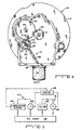
- Fig. 3 is a block diagram of the flow circuit arrangement of the oil filtration system of the present invention in combination with the oil lubrication circuit of the engine;
- Fig. 4 is a top plan view of the internal combustion engine of Fig. 1 employing the lubrication oil filtration system of the present invention with an upper portion of the engine block removed;
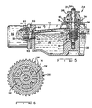
- Fig. 5 is an enlarged fragmentary elevational view, taken along line 5-5 of Fig. 4 partly in cross- section, with portions broken away;
- Fig. 6 is an enlarged plan view of the driven gear of the engine governor.
- Corresponding reference characters indicate corresponding parts throughout the several views of the drawings.
- The exemplifications set out herein illustrate a preferred embodiment of the invention, in one form thereof, and such exemplifications are not to be construed as limiting the scope of the disclosure or the scope of the invention in any manner.
- Referring now to the drawings and particularly to Figs. 1 and 2, there is shown the portion of a conventional small internal combustion engine, generally designated 10, which includes the components with which the lubricating
oil filtration system 12, as shown in Figs. 2 and 5, may be employed. -
Engine 10 typically includes a main casting or block 14 which houses and rotatably supports a vertically oriented crankshaft or driveshaft 16 having an off-setportion 18 which, via a connecting rod (not shown), is joined to a piston (not shown) which is mounted for reciprocable movement within a cylinder (not shown) in theengine block 14. The reciprocable motion of the piston is translated into rotary motion of thedrive shaft 16 due to the interconnection of the piston with the off-setshaft portion 18 by the connecting rod. Driveshaft 16 includes an output end 20 to which is attached a motion transmitting device (not shown), such as a gear, pulley, or the like for connection to a device such as a mower and the like for performance of useful work. - As is well known, the reciprocatory speed of the piston, and therefore the rotational speed of
drive shaft 16, are determined by the rate at which a combustable fuel-air mixture is fed to the cylinder (not shown) via a carburetor 22 of the engine. As conventionally practiced,engine 10 has agovernor 24 driven bydrive shaft 16 which controls a throttle valve (not shown) mounted on ashaft 21 in carburetor 22. The throttle valve regulates the feed rate at which the combustable fuel-air mixture is fed to the cylinder. Achoke valve 23 is also provided for determining the fuel to air ratio of the mixture of which is fed to the cylinder. The maximum speed at which the engine runs is controlled by adjustment of a handthrottle control lever 25 which is connected to throttlevalve shaft 21. The operation of the carburetor is conventional and forms no part of the present invention and therefore need not be further explained herein. -
Governor 24 is rotatably driven bydrive shaft 16 and regulates the throttle valve (not shown) through aconventional linkage 26 to maintain constant the rate at which the combustable fuel-air mixture is fed to the cylinder for a specific setting of the throttle control, under various engine loading conditions. The governor operates on the basis of centrifugal speed for maintaining constant the rotational speed of the engine. The operation of the throttle control governor is also conventional, forms no part of the instant invention, and is therefore not explained further herein. -
Throttle governor 24, as seen in Fig. 5, includes asupport housing 28 which is located adjacent anoil sump 30 ofengine 10 and defines ahollow cavity 32.Governor 24 further includes asupport shaft 34 mounted withinhousing 28 and extending generally centrally ofcavity 32 and upwardly above it. Additionally,governor 24 includes a drivengear 36 rotatably mounted onsupport shaft 34 abovehousing 28. As is conventional,governor 24 includes aspool member 37 which is operated by twolugs 39 mounted for pivotable movement on drivengear 36. As drivengear 36 rotates, centrifugal force will causelugs 39 to pivot outwardly thereby causingspool 37 to be lifted upwardly to operatelinkage 26 thereby. As best seen in Fig. 4, governor drivengear 36 is drivingly interconnected withdrive gear 38 carried ondrive shaft 16 of the engine via an intermediatelarger diameter gear 40. - Referring now to Fig. 3, it is shown diagrammatically that
oil sump 30 serves as the main oil reservoir for anoil lubricating system 42 in the main oil lubricating circuit, generally designated 44, ofengine 10. Further,oil filtering circuit 12 of the present invention is shown disposed in parallel circuit arrangement with mainoil lubricating circuit 44 and connected in flow communication withoil sump 30 ofengine 10. - Main
oil lubricating circuit 44 includes amain oil pump 46 driven by drive means 48 which includesengine drive shaft 16,intermediate gear 40, andcam shaft 49. As best seen in Fig. 2pump 46 preferably comprises a barrel type of lubrication pump. - However, it should be understood that other types of pumps may be substituted for
barrel type pump 46.Oil lubricating system 42, which may be provided by any number of suitable conventional arrangements, lubricates drive means 48 as represented by the dashed line connecting drive means 48 withlubrication system 42.Oil sump 30 is connected in flow communication withlubricating system 42.Main oil pump 46 is connected in flow communication withsump 30 andlubricating system 42. Therefore, asmain pump 46 is driven by drive means 48, as indicated by the dashed line connecting the two, oil is pumped fromsump 30 throughcircuit 44 to lubricatingsystem 42 and back to the sump. -
Oil filtering system 12 of the present invention, being connected tooil sump 30 in parallel with mainoil lubricating circuit 44, includes an oil filtering means 50 in the form of a replaceable oil filter element disposedadjacent oil sump 30 and connected in flow communication therewith.Oil filtration circuit 12 further includes anoil pump 52 mounted incavity 32.Pump 52 is connected in flow communication withsump 30 andoil filter element 50 and is operably driven by drive means 48 as represented by the dashed line connecting drive means 48 andpump 52. Aspump 52 is driven, oil is pumped fromsump 30 tooil filter element 50 and back tosump 30. - Turning now to Figs. 4 and 5,
oil filtering system 12 of the present invention is illustrated in operative association with thethrottle control governor 24 ofengine 10. In the preferred embodiment,oil filtering system 12 includes anoil inlet 54 comprising a passage through the sump wall 55 and into a lower portion ofsupport housing 28 to provide flow communication betweencavity 32 andoil sump 30. Anoil outlet passage 56 through wall 55 of an upper portion ofsupport housing 28 provides flow communication betweencavity 32 and anoil filter element 50. Anoil discharge tube 58 interconnects supporthousing oil outlet 56 in flow communication withoil filter element 50 which is mounted to awall 57 ofsump 30 by afilter adapter plate 59. -
Adapter plate 59 is retained to exterior ofwall 57 ofsump 30 by a threadednipple 66 with anut 63. An "O" ring seal (not shown) is trapped betweensump wall 57 andfilter adapter plate 59 to seal theadapter plate 59 to wall 57.Ferrule 64 is pressed into a drilled hole in thesump wall 57 and is connected todischarge tube 58 and feeds contaminated oil throughaperture 60 to the outside offilter member 61 offilter element 50. The oil then flows throughfilter element member 61 to the center offilter element 50 and out of anoutflow orifice 62 innipple 66 tosump 30.Nipple 66 is threaded into thesump wall 57 and retainsfilter element 50 in place by threaded engagement therewith. -
Oil pump 52 offiltering system 12 utilizes a portion of thethrottle control governor 24 ofengine 10. Inparticular pump 52 includes ascrew type rotor 68 disposed incavity 32 and having helical threads 69 and forming ahelical passage 71 with the wall ofcavity 32. Threads 69, in the preferred embodiment, are square and have a pitch of 8 threads per inch.Rotor 68 is preferably constructed of molded plastic. The top thread ofrotor 68 is removed to form a circumferential groove incavity 32adjacent oil outlet 56.Helical screw 68 is rotatably mounted onsupport shaft 34 ofgovernor 24 below drivengear 36 of the governor.Gear 36 is drivingly connected to pumpscrew rotor 68. The driving interconnection betweengear 36 androtor 68 includes a plurality of tangs orteeth 72 formed on the upper end of pumpingscrew rotor 68. As best seen in Fig. 6 drivengear 36 includes anouter rim 74 havingdrive gear teeth 76 formed thereon.Gear 36 further includes aninner hub 78 spaced inwardly fromouter rim 74 for rotatably mountinggear 36 on thegovernor support shaft 34. A plurality of circumferentially spaced and radially extendingribs 80 interconnectouter rim 74 andinner hub 78.Tangs 72 ofscrew rotor 68 fit betweenradial ribs 80 ofgovernor gear 36 for drivingly interconnectinggear 36 andpump rotor 68. - In operation, when
engine 10 is operating and governor drivengear 36 is rotated, pumpscrew rotor 68 is rotatably driven bygear 36 and causes oil to flow throughinlet 54 intocavity 32.Helical passage 71 will carry the oil upwardly and will discharge the oil throughoutlet 56 anddischarge tube 58 to flow intofilter element 50 viaorifice 60. After proceeding throughoil filter element 50, where impurities are filtered from the oil byfilter element member 61, the oil flows thoughoutlet 62 innipple 66 and then back tooil sump 30. -
Filter element 50 should be replaced periodically as it will become clogged with impurities. However, it should be noted that, even iffilter element 50 becomes clogged with impurities and flow therethrough is inhibited, oil will still be circulated through the main lubrication system of the engine via lubricating circulatingcircuit 44 since filteringsystem 12 is arranged in parallel withlubrication circuit 44.
Claims (1)
- An oil filtering system for an engine including a drive shaft, a lubricating system (42) for the engine, an oil sump (30), a housing (28); an oil inlet means (54) defined in said housing (28) in flow communication with said oil sump (30); an oil outlet means (56) defined in said housing (28); an oil filtering means (50) disposed adjacent said oil sump (30) and having an inflow orifice (60) and an outflow orifice (62); means (58, 66) defining an oil filtering flow circuit separate from said lubricating system of the engine, said circuit means interconnecting said oil outlet means (56) of said housing (28) and said inflow orifice (60) and interconnecting said outflow orifice (62) and said oil sump (30); and oil pump means (52) causing oil flow from said sump (30) into said housing (28) via said inlet means (54) and from said housing (28) through said oil filtering means (50) and back to said sump (30), characterized in that(a) the oil filtering system forms an independent flow circuit separate from the engine lubrication, and is driven by a governor driven means (48) including a shaft (16) of a governor (24) for controlling the throttle of the engine;(b) the oil filtering means (50) is a removable oil filter element (61);(c) the oil flow circuit means includes an oil discharge tube (58) interconnecting the oil outlet means (56) of the housing (28) in flow communication with the inflow orifice (60) of the oil filtering means (50); (d) the oil flow circuit means includes means (66) connecting the outflow orifice (62) of the oil filtering means in flow communication with the oil sump (30);(e) the governor driven means (48) comprises a support shaft (34) disposed in the housing (28) and extending outwardly therefrom and a gear (36) rotatably supported by the support shaft (34) above said oil pumping means (52), wherein the oil pumping means (52) comprises a screw type member (68) disposed in the housing (28), rotatably mounted on the support shaft (34) and drivingly coupled to the gear (36).
Applications Claiming Priority (2)
| Application Number | Priority Date | Filing Date | Title |
|---|---|---|---|
| US797157 | 1985-11-12 | ||
| US06/797,157 US4648363A (en) | 1985-11-12 | 1985-11-12 | Lubricating oil filtration system for an engine |
Publications (3)
| Publication Number | Publication Date |
|---|---|
| EP0222089A2 EP0222089A2 (en) | 1987-05-20 |
| EP0222089A3 EP0222089A3 (en) | 1988-07-06 |
| EP0222089B1 true EP0222089B1 (en) | 1990-01-24 |
Family
ID=25170069
Family Applications (1)
| Application Number | Title | Priority Date | Filing Date |
|---|---|---|---|
| EP86112009A Expired - Lifetime EP0222089B1 (en) | 1985-11-12 | 1986-08-29 | Lubricating oil filtration system for an engine |
Country Status (7)
| Country | Link |
|---|---|
| US (1) | US4648363A (en) |
| EP (1) | EP0222089B1 (en) |
| JP (1) | JPS62113808A (en) |
| AU (1) | AU568795B2 (en) |
| CA (1) | CA1274137A (en) |
| DE (1) | DE3668491D1 (en) |
| NZ (1) | NZ217018A (en) |
Families Citing this family (51)
| Publication number | Priority date | Publication date | Assignee | Title |
|---|---|---|---|---|
| DE3516710A1 (en) * | 1985-05-09 | 1986-11-13 | Robert Bosch Gmbh, 7000 Stuttgart | CONTAINER ARRANGEMENT FOR VEHICLES WITH A COMMON OIL BUDGET |
| US4861467A (en) * | 1986-11-07 | 1989-08-29 | Fukuhara Seisaku Co., Ltd. | System for removing contaminants from an oil tank in a hydraulic device |
| JP2507024B2 (en) * | 1989-02-17 | 1996-06-12 | 日産自動車株式会社 | Engine casing |
| JP2503633Y2 (en) * | 1989-08-08 | 1996-07-03 | 株式会社明電舎 | Engine lubricating oil cleaning device |
| US5000143A (en) * | 1990-03-15 | 1991-03-19 | Lubrication Research, Inc. | Engine lubrication system with shared oil filter |
| US5085188A (en) * | 1990-12-03 | 1992-02-04 | Allied-Signal Inc. | Modular lubrication/filter system |
| JPH04132414U (en) * | 1991-05-29 | 1992-12-08 | 株式会社アツギユニシア | Internal combustion engine valve timing control device |
| US5611411A (en) * | 1996-05-10 | 1997-03-18 | Florida Power Corporation | Turbine lubrication oil filtration safeguard system |
| DE19629210A1 (en) * | 1996-07-22 | 1998-02-12 | Daimler Benz Ag | Internal combustion engine |
| US5894830A (en) * | 1997-12-15 | 1999-04-20 | Caterpillar Inc. | Engine having a high pressure hydraulic system and low pressure lubricating system |
| JP3562324B2 (en) * | 1998-07-14 | 2004-09-08 | 日産自動車株式会社 | Automatic transmission oil pump speed controller |
| US6082321A (en) * | 1998-07-29 | 2000-07-04 | Borgwarner Inc. | Method for controlling output pressure of an engine oil pump |
| US6161515A (en) * | 1998-07-29 | 2000-12-19 | Borgwarner Inc. | Method for controlling output pressure of an engine oil pump |
| US6289878B1 (en) | 1999-07-15 | 2001-09-18 | Caterpillar Inc. | Engine having multiple pumps driven by a single shaft |
| US6644262B2 (en) * | 2000-11-16 | 2003-11-11 | Honda Giken Kogyo Kabushiki Kaisha | Oil pump mounting structure for engine |
| US6742491B1 (en) * | 2002-12-17 | 2004-06-01 | Tecumseh Products Company | Engine lubrication system |
| RU2274753C2 (en) * | 2003-09-10 | 2006-04-20 | Открытое акционерное общество "Муромский ремонтно-механический завод" | Lubrication system of internal combustion engine |
| CN101124406A (en) * | 2004-04-20 | 2008-02-13 | 金属达因有限责任公司 | Device for controlling parasitic losses in fluid pumps |
| US7775966B2 (en) | 2005-02-24 | 2010-08-17 | Ethicon Endo-Surgery, Inc. | Non-invasive pressure measurement in a fluid adjustable restrictive device |
| US8066629B2 (en) | 2005-02-24 | 2011-11-29 | Ethicon Endo-Surgery, Inc. | Apparatus for adjustment and sensing of gastric band pressure |
| US7927270B2 (en) | 2005-02-24 | 2011-04-19 | Ethicon Endo-Surgery, Inc. | External mechanical pressure sensor for gastric band pressure measurements |
| US7658196B2 (en) | 2005-02-24 | 2010-02-09 | Ethicon Endo-Surgery, Inc. | System and method for determining implanted device orientation |
| US8016744B2 (en) | 2005-02-24 | 2011-09-13 | Ethicon Endo-Surgery, Inc. | External pressure-based gastric band adjustment system and method |
| US7699770B2 (en) | 2005-02-24 | 2010-04-20 | Ethicon Endo-Surgery, Inc. | Device for non-invasive measurement of fluid pressure in an adjustable restriction device |
| US7775215B2 (en) | 2005-02-24 | 2010-08-17 | Ethicon Endo-Surgery, Inc. | System and method for determining implanted device positioning and obtaining pressure data |
| US8152710B2 (en) | 2006-04-06 | 2012-04-10 | Ethicon Endo-Surgery, Inc. | Physiological parameter analysis for an implantable restriction device and a data logger |
| US8870742B2 (en) | 2006-04-06 | 2014-10-28 | Ethicon Endo-Surgery, Inc. | GUI for an implantable restriction device and a data logger |
| US20080041664A1 (en) * | 2006-08-16 | 2008-02-21 | Giw Industries, Inc. | Dry sump lubrication system for centrifugal pumps |
| US8522925B2 (en) * | 2006-08-22 | 2013-09-03 | Metaldyne Company Llc | Debris flush system for balance shaft bearings |
| US8187163B2 (en) | 2007-12-10 | 2012-05-29 | Ethicon Endo-Surgery, Inc. | Methods for implanting a gastric restriction device |
| US8100870B2 (en) | 2007-12-14 | 2012-01-24 | Ethicon Endo-Surgery, Inc. | Adjustable height gastric restriction devices and methods |
| US8377079B2 (en) | 2007-12-27 | 2013-02-19 | Ethicon Endo-Surgery, Inc. | Constant force mechanisms for regulating restriction devices |
| US8142452B2 (en) | 2007-12-27 | 2012-03-27 | Ethicon Endo-Surgery, Inc. | Controlling pressure in adjustable restriction devices |
| US8591395B2 (en) | 2008-01-28 | 2013-11-26 | Ethicon Endo-Surgery, Inc. | Gastric restriction device data handling devices and methods |
| US8192350B2 (en) | 2008-01-28 | 2012-06-05 | Ethicon Endo-Surgery, Inc. | Methods and devices for measuring impedance in a gastric restriction system |
| US8337389B2 (en) | 2008-01-28 | 2012-12-25 | Ethicon Endo-Surgery, Inc. | Methods and devices for diagnosing performance of a gastric restriction system |
| US8221439B2 (en) | 2008-02-07 | 2012-07-17 | Ethicon Endo-Surgery, Inc. | Powering implantable restriction systems using kinetic motion |
| US7844342B2 (en) | 2008-02-07 | 2010-11-30 | Ethicon Endo-Surgery, Inc. | Powering implantable restriction systems using light |
| US8114345B2 (en) | 2008-02-08 | 2012-02-14 | Ethicon Endo-Surgery, Inc. | System and method of sterilizing an implantable medical device |
| US8057492B2 (en) | 2008-02-12 | 2011-11-15 | Ethicon Endo-Surgery, Inc. | Automatically adjusting band system with MEMS pump |
| US8591532B2 (en) | 2008-02-12 | 2013-11-26 | Ethicon Endo-Sugery, Inc. | Automatically adjusting band system |
| US8034065B2 (en) | 2008-02-26 | 2011-10-11 | Ethicon Endo-Surgery, Inc. | Controlling pressure in adjustable restriction devices |
| US8187162B2 (en) | 2008-03-06 | 2012-05-29 | Ethicon Endo-Surgery, Inc. | Reorientation port |
| US8233995B2 (en) | 2008-03-06 | 2012-07-31 | Ethicon Endo-Surgery, Inc. | System and method of aligning an implantable antenna |
| DE202009013851U1 (en) * | 2009-10-12 | 2010-03-04 | Triboserv Gmbh & Co. Kg | lubrication pump |
| RU2491428C1 (en) * | 2012-04-09 | 2013-08-27 | Государственное Научное Учреждение "Объединенный Институт Машиностроения Национальной Академии Наук Беларуси" | Ice lubrication system |
| CN109306884A (en) * | 2017-07-28 | 2019-02-05 | 福特环球技术公司 | Oil pan assembly with integrated oil filter |
| CN107354615B (en) * | 2017-09-11 | 2023-02-03 | 浙江中捷缝纫科技有限公司 | Oil supply system of sewing machine |
| CN108547679B (en) * | 2018-04-09 | 2020-07-28 | 山东交通学院 | Oil pan with machine oil purification performance |
| US12564801B2 (en) * | 2021-03-18 | 2026-03-03 | Volvo Truck Corporation | Oil filter with two filtrate outlets and vehicle lubrication circuit |
| CN115388315B (en) * | 2022-09-02 | 2024-08-06 | 中国航发贵阳发动机设计研究所 | Oil collecting tank structure for aero-engine |
Citations (2)
| Publication number | Priority date | Publication date | Assignee | Title |
|---|---|---|---|---|
| US1986539A (en) * | 1930-05-20 | 1935-01-01 | Schmidt Fritz | Forced-lubrication system |
| US3078958A (en) * | 1959-05-30 | 1963-02-26 | Porsche Kg | Internal combustion engine arrangement |
Family Cites Families (15)
| Publication number | Priority date | Publication date | Assignee | Title |
|---|---|---|---|---|
| US1447245A (en) * | 1923-03-06 | Warren w | ||
| US2533575A (en) * | 1945-06-28 | 1950-12-12 | Continental Motors Corp | Internal-combustion engine |
| US2621605A (en) * | 1945-10-12 | 1952-12-16 | Clayton Mark & Company | Pump |
| US2539619A (en) * | 1945-10-22 | 1951-01-30 | Leonard B Goodall | Engine lubricating system |
| US2719667A (en) * | 1951-01-11 | 1955-10-04 | Ohio Crankshaft Co | Lubricating system for rotating equipment having a vertical shaft |
| US2737933A (en) * | 1952-10-11 | 1956-03-13 | Minneapolis Moline Co | Engine |
| US2842112A (en) * | 1954-12-20 | 1958-07-08 | Exxon Research Engineering Co | Method for reducing corrosion in lubrication systems |
| FR1238854A (en) * | 1959-07-08 | 1960-08-19 | F Christol Ets | In-service lubricating oil regeneration process |
| US3037582A (en) * | 1961-04-13 | 1962-06-05 | Goodall Mfg Corp | Combination oil reservoir and bearing mount for internal combustion engines |
| US3144097A (en) * | 1962-08-30 | 1964-08-11 | Briggs & Stratton Corp | Oil slinger |
| CH415305A (en) * | 1963-03-06 | 1966-06-15 | Ryffel Hans | Screw pump |
| US3429304A (en) * | 1967-06-21 | 1969-02-25 | Continental Motors Corp | Engine accessory drive construction |
| US3707202A (en) * | 1970-07-31 | 1972-12-26 | Roy H Dixon | Oil filter in crankcase pan |
| JPS5339806U (en) * | 1976-09-10 | 1978-04-06 | ||
| JPS5550331U (en) * | 1978-09-28 | 1980-04-02 |
-
1985
- 1985-11-12 US US06/797,157 patent/US4648363A/en not_active Expired - Fee Related
-
1986
- 1986-07-29 NZ NZ217018A patent/NZ217018A/en unknown
- 1986-07-31 CA CA000515118A patent/CA1274137A/en not_active Expired - Fee Related
- 1986-08-11 AU AU61050/86A patent/AU568795B2/en not_active Ceased
- 1986-08-29 DE DE8686112009T patent/DE3668491D1/en not_active Expired - Fee Related
- 1986-08-29 EP EP86112009A patent/EP0222089B1/en not_active Expired - Lifetime
- 1986-09-05 JP JP61208133A patent/JPS62113808A/en active Pending
Patent Citations (2)
| Publication number | Priority date | Publication date | Assignee | Title |
|---|---|---|---|---|
| US1986539A (en) * | 1930-05-20 | 1935-01-01 | Schmidt Fritz | Forced-lubrication system |
| US3078958A (en) * | 1959-05-30 | 1963-02-26 | Porsche Kg | Internal combustion engine arrangement |
Also Published As
| Publication number | Publication date |
|---|---|
| AU6105086A (en) | 1987-05-14 |
| EP0222089A2 (en) | 1987-05-20 |
| AU568795B2 (en) | 1988-01-07 |
| US4648363A (en) | 1987-03-10 |
| EP0222089A3 (en) | 1988-07-06 |
| DE3668491D1 (en) | 1990-03-01 |
| JPS62113808A (en) | 1987-05-25 |
| CA1274137A (en) | 1990-09-18 |
| NZ217018A (en) | 1987-10-30 |
Similar Documents
| Publication | Publication Date | Title |
|---|---|---|
| US4648363A (en) | Lubricating oil filtration system for an engine | |
| US4662328A (en) | Governor driven pump for an engine | |
| US5525225A (en) | Fuel filter with internal vent | |
| JP3373597B2 (en) | Fuel filter with internal vent | |
| EP0164882B1 (en) | Oil cleaning assemblies for engines | |
| US5279391A (en) | Dry sump mechanical transmission | |
| DE69407880T2 (en) | Oil supply system for a scroll compressor | |
| IT1192015B (en) | FILTER FOR INTERNAL COMBUSTION ENGINE LUBRICANTS WITH RESERVE OF ADDITIVES | |
| GB2130653A (en) | Internal combustion engine lubrication system | |
| DE68907603T2 (en) | LUBRICATION SYSTEM FOR INTERNAL COMBUSTION ENGINE. | |
| GB2026612A (en) | Rotary positive-displacement fluid-machines | |
| US4131396A (en) | Hermetic compressor lubrication system with two-stage oil pump | |
| DD228183A5 (en) | METHOD AND CYCLIC SEPARATOR FOR CLEANING FLUIDS | |
| EP0662337A2 (en) | Fuel filter with internal vent | |
| CN1126797A (en) | Lubrication system of internal combustion engine | |
| EP0681094A1 (en) | Fluid filters | |
| US4911119A (en) | Oil pump mounting system for internal combustion engines | |
| US5558058A (en) | Four stroke engine with combined oil pump and filter assembly | |
| EP0657198A2 (en) | Single stage fuel filter with seal control air purge | |
| US5950591A (en) | Engine oil deterioration preventing agent and device | |
| CN220204016U (en) | General purpose petrol engine | |
| EP1937999B1 (en) | Power train mechanism | |
| JP3853092B2 (en) | Liquid filter | |
| EP2134936B1 (en) | Pitot engine crankshaft oil pump | |
| US2902012A (en) | Pump lubrication means |
Legal Events
| Date | Code | Title | Description |
|---|---|---|---|
| PUAI | Public reference made under article 153(3) epc to a published international application that has entered the european phase |
Free format text: ORIGINAL CODE: 0009012 |
|
| AK | Designated contracting states |
Kind code of ref document: A2 Designated state(s): DE FR GB IT |
|
| PUAL | Search report despatched |
Free format text: ORIGINAL CODE: 0009013 |
|
| AK | Designated contracting states |
Kind code of ref document: A3 Designated state(s): DE FR GB IT |
|
| 17P | Request for examination filed |
Effective date: 19880615 |
|
| 17Q | First examination report despatched |
Effective date: 19890120 |
|
| GRAA | (expected) grant |
Free format text: ORIGINAL CODE: 0009210 |
|
| AK | Designated contracting states |
Kind code of ref document: B1 Designated state(s): DE FR GB IT |
|
| ET | Fr: translation filed | ||
| REF | Corresponds to: |
Ref document number: 3668491 Country of ref document: DE Date of ref document: 19900301 |
|
| ITF | It: translation for a ep patent filed | ||
| PGFP | Annual fee paid to national office [announced via postgrant information from national office to epo] |
Ref country code: GB Payment date: 19900629 Year of fee payment: 5 |
|
| PGFP | Annual fee paid to national office [announced via postgrant information from national office to epo] |
Ref country code: FR Payment date: 19900828 Year of fee payment: 5 |
|
| ITTA | It: last paid annual fee | ||
| PGFP | Annual fee paid to national office [announced via postgrant information from national office to epo] |
Ref country code: DE Payment date: 19901006 Year of fee payment: 5 |
|
| PLBE | No opposition filed within time limit |
Free format text: ORIGINAL CODE: 0009261 |
|
| STAA | Information on the status of an ep patent application or granted ep patent |
Free format text: STATUS: NO OPPOSITION FILED WITHIN TIME LIMIT |
|
| 26N | No opposition filed | ||
| PG25 | Lapsed in a contracting state [announced via postgrant information from national office to epo] |
Ref country code: GB Effective date: 19910829 |
|
| GBPC | Gb: european patent ceased through non-payment of renewal fee | ||
| PG25 | Lapsed in a contracting state [announced via postgrant information from national office to epo] |
Ref country code: FR Effective date: 19920430 |
|
| PG25 | Lapsed in a contracting state [announced via postgrant information from national office to epo] |
Ref country code: DE Effective date: 19920501 |
|
| REG | Reference to a national code |
Ref country code: FR Ref legal event code: ST |
|
| PG25 | Lapsed in a contracting state [announced via postgrant information from national office to epo] |
Ref country code: IT Free format text: LAPSE BECAUSE OF NON-PAYMENT OF DUE FEES;WARNING: LAPSES OF ITALIAN PATENTS WITH EFFECTIVE DATE BEFORE 2007 MAY HAVE OCCURRED AT ANY TIME BEFORE 2007. THE CORRECT EFFECTIVE DATE MAY BE DIFFERENT FROM THE ONE RECORDED. Effective date: 20050829 |