EP0221784A2 - Nockensperre - Google Patents
Nockensperre Download PDFInfo
- Publication number
- EP0221784A2 EP0221784A2 EP86308535A EP86308535A EP0221784A2 EP 0221784 A2 EP0221784 A2 EP 0221784A2 EP 86308535 A EP86308535 A EP 86308535A EP 86308535 A EP86308535 A EP 86308535A EP 0221784 A2 EP0221784 A2 EP 0221784A2
- Authority
- EP
- European Patent Office
- Prior art keywords
- cam
- cam wheel
- aperture
- wheel
- spring
- Prior art date
- Legal status (The legal status is an assumption and is not a legal conclusion. Google has not performed a legal analysis and makes no representation as to the accuracy of the status listed.)
- Withdrawn
Links
Images


Classifications
-
- A—HUMAN NECESSITIES
- A01—AGRICULTURE; FORESTRY; ANIMAL HUSBANDRY; HUNTING; TRAPPING; FISHING
- A01M—CATCHING, TRAPPING OR SCARING OF ANIMALS; APPARATUS FOR THE DESTRUCTION OF NOXIOUS ANIMALS OR NOXIOUS PLANTS
- A01M31/00—Hunting appliances
- A01M31/02—Shooting stands
Definitions
- a cam locking device which comprises a base portion having two leg portions capable of holding an eccentrically mounted cam wheel.
- the cam wheel pivots on a pin passing through holes in each of the leg portions.
- the cam is of such diameter and positioned eccentrically such that it cannot rotate in a complete 360 degree arc without jamming a portion of the rope or strap between the cam and the base portion. Ridges on the cam periphery increase the gripping strength of the cam lock. Other ridges or protrusions on the cam periphery allow the cam to be manually gripped and released, thus facilitating strap or rope adjustment of the diameter of the loop around the tree and during ascension or descension of the tree seat.
- the cam lock mechanism also includes a spring to bias the cam into a rope engaging position and a bushing to hold the spring in place.
- the aforementioned spring mechanism insures that the cam is always in a ready-to-lock position unless physically held otherwise.
- Various embodiments of the cam locking device are disclosed.
- the base portion is either bolted to the tree stand or attached to the tree stand via a pivot, allowing the strap to be pivoted to facilitate the ascending or descending motion of the stand.
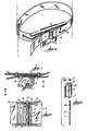
- Figures l, 2 and 4 show the use of the cam lock to secure the belt on a tree climbing aid.
- Reference character l generally indicates a cam lock device comprising a base plate 2 with two upstanding legs 3 at right angles with the base plate 2.
- the base plate is secured to strap 5 by rivets holding an eccentric cam wheel 4 between them.
- a strap 5 encircling a tree is positioned between the two leg portions 3 and between the base plate 2 and the wheel 4.
- the wheel 4 has an off-center eccentric axis 6, which is placed such that the wheel 4 cannot rotate through a 360 degree circle without jamming or engaging against the strap 5 and base 2 thus precluding strap movement in one direction when jammed.
- the axis is provided by a cylindrical pin 7 inserted through one leg opening 8, through the cam wheel opening 9 or aperture and then through the second identical leg 8 opening.
- the end l0 of pin 7 may be flattened to secure the pin in position.
- a coil spring ll is arranged around one end of the pin. The outside diameter of the spring is less than the diameter of aperture 9 and the coil of spring ll is located inside aperture 9. End l3 of the spring is secured in a slot l2 in the wheel. The other end of the spring l4 attaches to an opening l5 in one of the legs 3.
- the bushing l6 has an axial length less than the thickness of the cam wheel.
- the spring ll is held in axial position adjacent to the leg by a bushing l6 on pin 7. The spring torques the cam wheel 4 against the strap 5 and base plate 2. Tension upon the strap 5 in one direction will cause the cam wheel l to jam, thus securing the strap 5, while tension upon the strap 5 in the opposite direction will release the cam lock l
- a raised ridge or protrusion l7 upon the periphery of the cam 4 parallel to the cam axis 6 but opposite to the point of jamming is positioned such that raising the ridge l7 releases the cam wheel 4.
- Further raised ridges l8 on the periphery of the cam 4 are positioned parallel to the cam axis 6 along the surface where the face of the surface meets the strap 5 and base 2, providing added gripping strength and friction.
- Washers l9 are arranged on the pin 7 between the cam 4 and each leg 3.
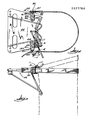
- FIGs. 5 and 6 the cam lock l is shown in association with a tree stand or seat 22.
- the base plate 2 is secured to a pivot 20.
- the pivot 20 consists of a generally u-shaped bracket 2l which slides over the edge of platform 22.
- Each leg 23 of the bracket has two holes 24 through which bolts 25 are inserted, those holes matching holes in the platform 22.
- the cam lock base plate 2 is secured by bolts 27, nuts 28 and washer 29 to the closed end 30 of the u- shaped bracket 2l through a hole 3l in the end 30 and a hole 32 in the cam lock base 2.
- Two washers 33 are positioned between end 30 and cam lock base 2 to allow free pivotal movement of the cam lock about an axis parallel to the platform 22 so that the angle of the strap 5 relative to the platform can be adjusted as shown in broken lines Figure 5. This enables more efficient use of the tree seat.
- the cam lock base 2 is bolted directly in position on the tree stand 22 by means of bolts inserted through holes at each of the bases' corners.
- Figures 8, 9 and l0 show a modified embodiment of the cam lock of the invention in which the cam wheel 50 is pivotally supported by a pin or shaft 52 which has a diameter slightly less than the diameter of through aperture 54 in the cam wheel 50.
- the spring 56 is located within the bushing 58, both of which are arranged around the pin 52.
- Bushing or spacer 58 positions the cam wheel 50 at one side of the u-shaped opening 60 and against one leg 62.
- One end 64 of the spring is engaged in a hole in a leg 62 and the other end of the spring 56 (Fig. l0) is engaged in aperture 68 in the cam wheel 54.
- Fig. ll is a modified embodiment of the arrangement as shown in Figs. 8, 9 and l0 in which the spring coil 90 is located in aperture 92 in the cam wheel 94.
- the spring serves as a bearing for the cam wheel and the ends of the spring are engaged one in the cam wheel and one in the leg of the bracket.
- the spacer or bushing 96 maintains the spring in appropriate axial position and also holds the cam wheel in an appropriate position.
- a T-shaped mounting plate 72 which can be secured to the bow deck 74 of a ship by fasteners extending through apertures 76.
- the plate 72 is integrally formed with a pair of spaced plate portions 78 having apertures to support a pin 80 for a pulley wheel 82.
- a hood 84 which protects the rope 86 from being dislodged from the pulley wheel 82.
- the cam lock can be utilized with the bracket as shown by manually manipulating the rope under the cam wheel to lock the rope in a fixed position holding the anchor off the ground or above the water.
- the rope can be manually manipulated into the broken line position to position the rope in the slot free of the cam wheel so that it can be released to drop the anchor from a secured position.
- the cam lock can be mounted inside the boat about a vertical axis for convenience of the operator.
- Figs. l2, l3, l4 and l5 show a modified version of the cam lock in which engagement and release of the cam wheel is afforded by a crank which can be connected to a rope or cable for remote operation thereof.
- a U-shaped mounting bracket l00 is provided with upstanding legs l02 and l04 and a base plate or web portion l06.
- the cam wheel l08 is supported by a shaft in the form of a bolt ll0.
- Means are provided for adjusting the position of the bolt ll0 relative to the base plate l06 to increase the gap between the wheel l08 and the plate to release or grip a rope ll2 located therebetween.
- the means includes apertures ll4 in the base plates legs l02 and l04 and bushings ll6 which have a hub ll8 which rotatably interfits in aperture ll4 and is rotatably supported in the aperture ll4.
- the bushings ll6 are provided with eccentrically located apertures l20 sized to receive bolt ll0 at a point offset from the center l22 of the bushing which would also be the center of the aperture ll4.
- Crank means l24 are provided to rotate the bushings ll6 to change the position of the bolt axis ll0 and hence the cam wheel l08 relative to the base plate.
- crank means comprises L-shaped arm portions l25 which are connected by a web portion l26 to form a U-shaped crank.
- Crank ends l28 are provided with apertures l30 to receive the bolt ll0.
- the end l28 is received in a slot l32 in the face of the bushing ll6 which positively positions the crank with respect to the bushing so that there is no relative movement between the crank and bushing.
- a rope l36 connected to the web l26 enables movement of the crank from the position shown in Fig. l3 where the cam wheel is engaged with the rope to a released position as shown in Fig. l2 where the gap between the cam wheel has been increased and the cam released from the rope.
- Changing the position of the crank changes the position of the arc of travel of the periphery of the cam wheel between rope engaging and rope disengaging arcs.
- Means are provided for securing the crank in a locked or unlocked position.
- the means comprises a pin or plunger 140 secured to a spring leaf 142 which can pop into an aperture 144 or 146 in a leg 102 to secure the crank in a locked or unlocked position.
- cam wheel 108 is sized so that it cannot make a 360 degree rotation
- a small cam wheel 108 can be employed that can clear the web 106 and rotate 360 degrees. In that situation a larger throw of the offset axis 120 of the bushing would be appropriate.
Landscapes
- Life Sciences & Earth Sciences (AREA)
- Engineering & Computer Science (AREA)
- Insects & Arthropods (AREA)
- Pest Control & Pesticides (AREA)
- Wood Science & Technology (AREA)
- Zoology (AREA)
- Environmental Sciences (AREA)
- Clamps And Clips (AREA)
- Emergency Lowering Means (AREA)
Applications Claiming Priority (2)
| Application Number | Priority Date | Filing Date | Title |
|---|---|---|---|
| US794002 | 1985-11-01 | ||
| US06/794,002 US4648483A (en) | 1985-11-01 | 1985-11-01 | Cam lock |
Publications (2)
| Publication Number | Publication Date |
|---|---|
| EP0221784A2 true EP0221784A2 (de) | 1987-05-13 |
| EP0221784A3 EP0221784A3 (de) | 1988-10-12 |
Family
ID=25161390
Family Applications (1)
| Application Number | Title | Priority Date | Filing Date |
|---|---|---|---|
| EP86308535A Withdrawn EP0221784A3 (de) | 1985-11-01 | 1986-10-31 | Nockensperre |
Country Status (2)
| Country | Link |
|---|---|
| US (1) | US4648483A (de) |
| EP (1) | EP0221784A3 (de) |
Families Citing this family (34)
| Publication number | Priority date | Publication date | Assignee | Title |
|---|---|---|---|---|
| US4791908A (en) * | 1987-09-17 | 1988-12-20 | Pro Line Company | Bowstring release mechanism |
| US4809815A (en) * | 1988-04-19 | 1989-03-07 | Wallace Donald R | Hand climber for hunting uses |
| US4936416A (en) * | 1988-10-11 | 1990-06-26 | Garon Joseph M | Theft resistant portable tree stand with enhanced stability |
| US4998327A (en) * | 1990-04-11 | 1991-03-12 | Hull Harold L | Traction hook and rope lock |
| US5234076A (en) * | 1990-09-14 | 1993-08-10 | Louk Robert L | Tree stand |
| US5454445A (en) * | 1992-05-06 | 1995-10-03 | Berryman; Larry O. | Observation and hunting stand |
| US5257677A (en) * | 1992-11-24 | 1993-11-02 | Stepp James L | Climbing device for columnar members, such as trees, poles and the like |
| USD352558S (en) | 1992-11-24 | 1994-11-15 | Stepp James L | Bracket for a tree climber |
| US20050247525A1 (en) * | 2004-05-05 | 2005-11-10 | Thornton Grayson D | Tree stand rope grip apparatus and method |
| US7802653B2 (en) * | 2005-01-14 | 2010-09-28 | Louk John M | Adjustable tree stand |
| US7263750B2 (en) | 2005-06-09 | 2007-09-04 | Amsafe, Inc. | Buckle assembly having single release for multiple belt connectors |
| WO2009094404A1 (en) * | 2008-01-22 | 2009-07-30 | Amsafe Commercial Products, Inc. | Buckle assemblies and associated connectors for use with child seats and other restraint systems |
| US8303043B2 (en) * | 2008-09-29 | 2012-11-06 | Amsafe, Inc. (Phoenix Group) | Tensioning apparatuses for occupant restraint systems and associated systems and methods |
| US7904997B2 (en) | 2008-11-07 | 2011-03-15 | Amsafe, Inc. | Buckles for inflatable personal restraint systems and associated systems and methods |
| US20100125986A1 (en) * | 2008-11-25 | 2010-05-27 | Armstrong Richard W | Locking Mechanism for A Tie Down |
| US8469401B2 (en) | 2009-02-23 | 2013-06-25 | Amsafe, Inc. | Seat harness pretensioner |
| CA2719846A1 (en) * | 2009-11-02 | 2011-05-02 | Amsafe Commercial Products, Inc. | Devices for adjusting tension in seat belts and other restraint system webs, and associated methods |
| US8683666B2 (en) | 2009-11-04 | 2014-04-01 | Amsafe Commercial Products, Inc. | Restraint system buckle components having tactile surfaces, and associated methods of use and manufacture |
| US8627554B1 (en) | 2010-05-03 | 2014-01-14 | Amsafe, Inc. (Phoenix Group) | Buckle assemblies with swivel and dual release features and associated methods of use and manufacture |
| US8777323B2 (en) | 2010-07-20 | 2014-07-15 | Amsafe, Inc. | Restraint harnesses and associated methods of use and manufacture |
| USD661619S1 (en) | 2010-09-15 | 2012-06-12 | Amsafe Commercial Products, Inc. | Buckle assembly |
| USD655223S1 (en) | 2010-09-15 | 2012-03-06 | Amsafe Commercial Products, Inc. | Buckle assembly |
| US9022483B2 (en) | 2012-06-07 | 2015-05-05 | Shield Restraint Systems, Inc. | Seatbelt buckle tongue assembly |
| US8820487B2 (en) | 2012-11-29 | 2014-09-02 | Kearney-National Inc. | Rope arresting apparatus |
| EP2958453A4 (de) | 2013-02-19 | 2016-07-27 | Amsafe Inc | Schnallenanordnungen mit hebeverschlüssen und zugehörige verfahren und systeme |
| US9277788B2 (en) | 2013-02-19 | 2016-03-08 | Amsafe, Inc. | Dual release buckle assemblies and associated systems and methods |
| US9376050B1 (en) | 2015-05-15 | 2016-06-28 | Fgill Enterprises, L.L.C. | Resilient strap member with side rail assembly |
| US10086745B2 (en) * | 2014-01-29 | 2018-10-02 | Fgill Enterprises, L.L.C. | Resilient strap member |
| US9775410B2 (en) | 2014-12-16 | 2017-10-03 | Shield Restraint Systems, Inc. | Web adjusters for use with restraint systems and associated methods of use and manufacture |
| EP3355740A4 (de) | 2015-10-02 | 2019-10-30 | Shield Restraint Systems, Inc. | Lastindikatoren für personenhaltesysteme sowie zugehörige systeme und verfahren |
| US10604259B2 (en) | 2016-01-20 | 2020-03-31 | Amsafe, Inc. | Occupant restraint systems having extending restraints, and associated systems and methods |
| US9814282B2 (en) | 2016-02-02 | 2017-11-14 | Shield Restraint Systems, Inc. | Harsh environment buckle assemblies and associated systems and methods |
| US10611334B2 (en) | 2017-02-07 | 2020-04-07 | Shield Restraint Systems, Inc. | Web adjuster |
| CN112441153A (zh) * | 2019-08-29 | 2021-03-05 | 临颍县爬杆机器人有限公司 | 一种爬杆机器人 |
Family Cites Families (11)
| Publication number | Priority date | Publication date | Assignee | Title |
|---|---|---|---|---|
| US557800A (en) * | 1896-04-07 | Line-holder | ||
| US1250876A (en) * | 1917-02-16 | 1917-12-18 | Charles T Hicks | Clothes-line tightener. |
| US2442266A (en) * | 1945-04-09 | 1948-05-25 | Frank L Davis | Cargo tie-down |
| US2608174A (en) * | 1949-02-23 | 1952-08-26 | Norman S Sponenburg | Adjustable safety device for boat anchors |
| US3877679A (en) * | 1973-08-16 | 1975-04-15 | Lowe Alpine Systems Inc | Anchor device for mountain climbers |
| US3872550A (en) * | 1973-11-08 | 1975-03-25 | Pacific Scientific Co | Safety belt webbing adjustor |
| US3927733A (en) * | 1974-05-24 | 1975-12-23 | Isadore T Wurn | Outdoorsman{3 s folding chair |
| US3955645A (en) * | 1974-12-04 | 1976-05-11 | Dye James E | Tree climbing stand and loop |
| GB1588317A (en) * | 1977-06-04 | 1981-04-23 | Jardine R D | Climbing aids |
| FR2451752A1 (fr) * | 1979-03-23 | 1980-10-17 | Petzl Paul | Dispositif descendeur autobloquant perfectionne |
| US4542884A (en) * | 1983-06-06 | 1985-09-24 | Dodge Jr Cleveland E | Removable double action rope grip |
-
1985
- 1985-11-01 US US06/794,002 patent/US4648483A/en not_active Expired - Fee Related
-
1986
- 1986-10-31 EP EP86308535A patent/EP0221784A3/de not_active Withdrawn
Also Published As
| Publication number | Publication date |
|---|---|
| US4648483A (en) | 1987-03-10 |
| EP0221784A3 (de) | 1988-10-12 |
Similar Documents
| Publication | Publication Date | Title |
|---|---|---|
| US4648483A (en) | Cam lock | |
| US4716630A (en) | Cam lock with positive release | |
| EP0092317B1 (de) | Übungsgerät | |
| US4453486A (en) | Cam cleat | |
| US5774947A (en) | Anti-slip webbing adjuster | |
| US20040020727A1 (en) | Fall arrest device for a fixed rope | |
| JP3337685B2 (ja) | 自転車用変速機 | |
| US10258829B2 (en) | On-rope work positioning device | |
| US4883146A (en) | Descent control device with deadman brake | |
| EP0272782A1 (de) | Selbstblockierende Sicherheitsseilklemme | |
| US4356816A (en) | Traction device | |
| GB2027789A (en) | Clam cleat | |
| US20110109106A1 (en) | Lifting Assembly | |
| GB2141213A (en) | Rope grip | |
| WO1990010476A1 (fr) | Descendeur autobloquant pour corde a deux positions de blocage | |
| GB2157758A (en) | Improvements in or relating to a clamp assembly | |
| GB2044414A (en) | Self-locking descender | |
| JPH067470A (ja) | 安全装置 | |
| US4969373A (en) | Pedal assembly | |
| US5378216A (en) | Adjustment system for exercise machines | |
| US4399889A (en) | Load lowering apparatus | |
| US5417306A (en) | Tree climbing apparatus | |
| SE520052C2 (sv) | Anordning vid en för takmontage avsedd lastäbrare till fordon | |
| US6295936B1 (en) | Portable rope tow device | |
| KR20010052577A (ko) | 조정가능한 지지장치 및 지지장치를 조정하기 위한 구조물 |
Legal Events
| Date | Code | Title | Description |
|---|---|---|---|
| PUAI | Public reference made under article 153(3) epc to a published international application that has entered the european phase |
Free format text: ORIGINAL CODE: 0009012 |
|
| AK | Designated contracting states |
Kind code of ref document: A2 Designated state(s): DE FR GB IT NL |
|
| PUAL | Search report despatched |
Free format text: ORIGINAL CODE: 0009013 |
|
| AK | Designated contracting states |
Kind code of ref document: A3 Designated state(s): DE FR GB IT NL |
|
| STAA | Information on the status of an ep patent application or granted ep patent |
Free format text: STATUS: THE APPLICATION IS DEEMED TO BE WITHDRAWN |
|
| 18D | Application deemed to be withdrawn |
Effective date: 19890501 |