EP0220999B1 - Ferrure de verrouillage d'un ouvrant coulissant - Google Patents
Ferrure de verrouillage d'un ouvrant coulissant Download PDFInfo
- Publication number
- EP0220999B1 EP0220999B1 EP86440068A EP86440068A EP0220999B1 EP 0220999 B1 EP0220999 B1 EP 0220999B1 EP 86440068 A EP86440068 A EP 86440068A EP 86440068 A EP86440068 A EP 86440068A EP 0220999 B1 EP0220999 B1 EP 0220999B1
- Authority
- EP
- European Patent Office
- Prior art keywords
- latch
- control slot
- handle
- safety block
- fact
- Prior art date
- Legal status (The legal status is an assumption and is not a legal conclusion. Google has not performed a legal analysis and makes no representation as to the accuracy of the status listed.)
- Expired
Links
- 230000005540 biological transmission Effects 0.000 claims abstract description 14
- 230000002441 reversible effect Effects 0.000 claims abstract description 4
- 238000006073 displacement reaction Methods 0.000 claims 2
- 238000004519 manufacturing process Methods 0.000 description 1
Images
Classifications
-
- E—FIXED CONSTRUCTIONS
- E05—LOCKS; KEYS; WINDOW OR DOOR FITTINGS; SAFES
- E05B—LOCKS; ACCESSORIES THEREFOR; HANDCUFFS
- E05B63/00—Locks or fastenings with special structural characteristics
- E05B63/0056—Locks with adjustable or exchangeable lock parts
- E05B63/006—Locks with adjustable or exchangeable lock parts for different door thicknesses
-
- E—FIXED CONSTRUCTIONS
- E05—LOCKS; KEYS; WINDOW OR DOOR FITTINGS; SAFES
- E05B—LOCKS; ACCESSORIES THEREFOR; HANDCUFFS
- E05B65/00—Locks or fastenings for special use
- E05B65/08—Locks or fastenings for special use for sliding wings
- E05B65/087—Locks or fastenings for special use for sliding wings the bolts sliding parallel to the wings
Definitions
- the invention relates to a locking fitting for a sliding leaf composed of a latch and a sliding leaf lining, this lining comprising an inner plate provided with a handle integral with a control slide cooperating with the latch control element via a connecting element and an outer plate provided with a safety block cooperating with the control slide via its transmission part.
- a locking fitting for a sliding leaf composed of a latch and a sliding leaf lining, this lining comprising an inner plate capable of a handle integral with a slide.
- control cooperating with the latch control element via a connecting element and an outer plate provided with a safety block cooperating with the control slide via its transmission part which is characterized in that the control slide, cooperating with the latch control element and the safety block is removable and reversible and that it includes a boss projecting from one of its faces and in which a housing is produced penetrated by the transmission part of the safety block.
- This offset generally varies by half of the variation in the thickness of the sliding leaf, since the latch, generally centered with respect to the thickness of the sliding leaf, is displaced by half of the variation, while the safety block, integral with the outer plate, is displaced by the entire variation in the thickness of the sliding leaf.
- control slide comprises on each of its faces a plane facing the latch and a plane facing the safety block. This allows the reversibility of the control slide. Therefore, one can use the same fitting for sliding doors of different thicknesses. Indeed, the control slide can be used by one of its faces for a sliding leaf of a given thickness whereas by reversing the control slide one can use the other of its faces for a sliding leaf having another thickness.
- the handle is made integral with the control slide by at least one screw, the head of which constitutes the connecting element between the control slide and the latch.
- Another application of the invention is obtained by a design providing that the handle is made integral with the control slide by two screws, one of which comprises a head as a function of one of the faces of the control slide and whose the other has a head as a function of the other face of the control slide.
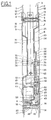
- Figure 1 shows, in elevation and in section, a sliding opening of a window or door having a locking fitting according to the invention.
- a sliding sash 3 of a window or a door a light 4, 5 in which one can accommodate a locking fitting 6.
- the latter is composed of a latch 7 and a sash trim sliding 8.
- the latch 7 is centered relative to the thickness of the sliding opening 3.
- the lining 8 comprises an outer plate 9, applied to the outer face 10 of the outer wall 1, and an inner plate 11 applied to the outer face 12 of the inner wall 2 of the sliding leaf 3. These two plates 9 and 11 are held together by fixing screws 13, 14 whose head 15, 16 is located on the side of the inner plate 11 and whose threaded rods 17, 18 are screwed into tapped sockets 19, 20 secured to the internal face 21 of the outer plate 9, the tapped sockets 19, 20 being located inside the openings 4, 5.
- the external plate 9 has a recess 22 serving as an external handle and making it possible to maneuver from the outside the sliding leaf 3.
- the internal plate 11 has a depression 23 making it possible to maneuver from the inside the sliding leaf 3.
- the latch 7 occupies the space available between the two recesses 22 and 23.
- a handle 26 making it possible to operate the latch 7 for closing and / or opening the sliding leaf 3 and, consequently, for closing and / or opening the window or door.
- the manipulation of the handle 26 is made possible by a gripping element 27 projecting relative to the external face 28 of the handle 26.
- This handle 26 makes it possible to actuate a control slide 29 interposed between the internal face 30 of the handle 26 and the internal face 31 of the latch 7.
- This control slide 29 moves in a light 32 produced in the bottom 25 of the recess 23.
- this slide 29 is removable, which makes it possible to adapt the latter to the thickness of the sliding opening 3.
- the control slide 29 is connected to the handle 26 by at least one removable connecting element 33.
- this connecting element is an elastic fixing element such as elastic rivet, stop screw with elastic washer.
- this connecting element is a screw 33, the threaded rod 34 of which, passing through the control slide 29, is screwed into a tapped bore 35 located at the location of the gripping element 26.
- this threaded bore 35 is blind and does not open onto the external face of the gripping element 27.
- This screw 33 is provided with a shoulder 36 which, during screwing, strongly applies the control slide 29 against the internal face 30 of the handle 26.
- the head 37 of the screw 33 at its free end 38 of the operating means 39 such as a slot for the end of a screwdriver, a hexagon socket or the like.
- this head 37 is used as a connecting element between the control slide 29 and a control element (not shown) of the latch 7. As a result, the opening or closing operation of the handle 26 is transmitted to the latch 7.
- the control slide 29 has a boss 40 projecting from one of the faces 41, 42 of the control slide 29.
- a housing 43 into which the transmission part 44 of a block penetrates.
- safety 45 is housed in a hub 46, integral with the internal face 21 of the outer plate 9 of the opening trim 8, and held in place by a retaining element 47 made integral with the hub 46 by at least a fixing element 48.
- the control stud 49 of the transmission part 44 of the safety block 45 can move in a transverse slot 50 produced in the boss 40 of the control slide 29.
- the latter comprises a plane 51 facing the latch 7, namely the plane comprising the connecting element 33 cooperating with the latch control element 7; and a plane 52 facing the safety block 45, namely the plane comprising the transverse lumen 50 cooperating with the control stud 49 of the transmission part 44 of the safety block 45.
- This offset between the planes 51 and 52 is equal to the difference between the minimum and maximum engagement depth of the connecting element 33 to the latch 7 and / or equal to the difference between the minimum and maximum engagement depth of the transmission part 44 of the safety block 45 in the housing 43 of the boss 40. Because of this offset, the same control slide 29 can be used for two different thicknesses of sliding leaf 3 and this is made possible by the fact that the control slide 29 is removable and reversible.
- each face 41, 42 of the control slide 29 comprises a plane 51 facing the latch 7 and a plane 52 facing the safety block 45
- the position of the control slide 29 is such that its face 41 includes the planes 51, 52 by turning the control slide 29, the planes 51, 52 are located on the side of the face 42, the plane 52 then being constituted by the outer face 53 of the boss 40.
- control slide 29 is made integral with the handle 26 by two connecting elements 33 and 54.
- the control slide 29 is turned over, to interchange the two connecting elements 33 and 54, that is to say putting the connecting element 54 in place of the connecting element 33 which, for its part, will be put in place of the connecting element 54.
Landscapes
- Engineering & Computer Science (AREA)
- Structural Engineering (AREA)
- Lock And Its Accessories (AREA)
- Closing And Opening Devices For Wings, And Checks For Wings (AREA)
- Transmission Devices (AREA)
- Wing Frames And Configurations (AREA)
- Harvester Elements (AREA)
- Slide Fasteners (AREA)
- Tents Or Canopies (AREA)
- Vehicle Step Arrangements And Article Storage (AREA)
- Mechanical Control Devices (AREA)
Priority Applications (1)
| Application Number | Priority Date | Filing Date | Title |
|---|---|---|---|
| AT86440068T ATE38700T1 (de) | 1985-09-26 | 1986-08-25 | Verriegelungseinrichtung eines schiebefluegels. |
Applications Claiming Priority (2)
| Application Number | Priority Date | Filing Date | Title |
|---|---|---|---|
| FR8514411 | 1985-09-26 | ||
| FR8514411A FR2587751B1 (fr) | 1985-09-26 | 1985-09-26 | Ferrure de verrouillage d'un ouvrant coulissant |
Publications (2)
| Publication Number | Publication Date |
|---|---|
| EP0220999A1 EP0220999A1 (fr) | 1987-05-06 |
| EP0220999B1 true EP0220999B1 (fr) | 1988-11-17 |
Family
ID=9323354
Family Applications (1)
| Application Number | Title | Priority Date | Filing Date |
|---|---|---|---|
| EP86440068A Expired EP0220999B1 (fr) | 1985-09-26 | 1986-08-25 | Ferrure de verrouillage d'un ouvrant coulissant |
Country Status (7)
| Country | Link |
|---|---|
| EP (1) | EP0220999B1 (enExample) |
| JP (1) | JPS6272872A (enExample) |
| AT (1) | ATE38700T1 (enExample) |
| CA (1) | CA1290366C (enExample) |
| DE (1) | DE3661211D1 (enExample) |
| FR (1) | FR2587751B1 (enExample) |
| HK (1) | HK5191A (enExample) |
Families Citing this family (7)
| Publication number | Priority date | Publication date | Assignee | Title |
|---|---|---|---|---|
| FR2632343B1 (fr) * | 1988-06-02 | 1990-08-17 | Ferco Int Usine Ferrures | Ferrure de verrouillage pour ouvrant coulissant |
| JPH0712572Y2 (ja) * | 1989-02-17 | 1995-03-29 | 株式会社ゴール | 扉 錠 |
| GR1000730B (el) * | 1991-09-24 | 1992-11-23 | Konstantinos Karagiannis | Χουφτα συρτης συρωμενων κουφωματων αλουμινιου. |
| GR950100280A (el) * | 1995-07-20 | 1997-03-31 | Κλειδαρια ασφαλειας χωνευτη για ολες τις σειρες συρομενων κουφωματων αλουμινιου με η χωρις κλειδι. | |
| FR2761720B1 (fr) * | 1997-04-03 | 1999-06-18 | Ferco Int Usine Ferrures | Ferrure de verrouillage pour ouvrant coulissant |
| GR1003323B (el) * | 1999-02-08 | 2000-02-24 | Κλειδαρια για πορτες και παραθυρα συρομενα αλουμινια | |
| WO2022181593A1 (ja) | 2021-02-26 | 2022-09-01 | 株式会社トクヤマ | 六方晶窒化ホウ素粉末およびその製造方法 |
Family Cites Families (2)
| Publication number | Priority date | Publication date | Assignee | Title |
|---|---|---|---|---|
| US3368374A (en) * | 1965-03-29 | 1968-02-13 | Adams Rite Mfg Company | Lock actuator and door pull |
| US3904229A (en) * | 1974-05-23 | 1975-09-09 | Ideal Security Hardware Co | Sliding door lock |
-
1985
- 1985-09-26 FR FR8514411A patent/FR2587751B1/fr not_active Expired
-
1986
- 1986-08-25 AT AT86440068T patent/ATE38700T1/de not_active IP Right Cessation
- 1986-08-25 DE DE8686440068T patent/DE3661211D1/de not_active Expired
- 1986-08-25 EP EP86440068A patent/EP0220999B1/fr not_active Expired
- 1986-09-08 CA CA000517693A patent/CA1290366C/fr not_active Expired - Lifetime
- 1986-09-25 JP JP61225035A patent/JPS6272872A/ja active Granted
-
1991
- 1991-01-17 HK HK51/91A patent/HK5191A/xx unknown
Also Published As
| Publication number | Publication date |
|---|---|
| EP0220999A1 (fr) | 1987-05-06 |
| FR2587751A1 (fr) | 1987-03-27 |
| DE3661211D1 (en) | 1988-12-22 |
| JPH0458875B2 (enExample) | 1992-09-18 |
| ATE38700T1 (de) | 1988-12-15 |
| CA1290366C (fr) | 1991-10-08 |
| HK5191A (en) | 1991-01-25 |
| JPS6272872A (ja) | 1987-04-03 |
| FR2587751B1 (fr) | 1987-11-20 |
Similar Documents
| Publication | Publication Date | Title |
|---|---|---|
| US4728133A (en) | Door handle attachment apparatus | |
| EP0220999B1 (fr) | Ferrure de verrouillage d'un ouvrant coulissant | |
| FR2584763A1 (fr) | Barillet de surete | |
| FR2631067A1 (fr) | Verrou a rotor debrayable | |
| CA1279675C (fr) | Ferrure de verrouillage avec pene reglable pour un ouvrant coulissant de fenetre, porte ou analogue | |
| US5685584A (en) | Adaptor spindle | |
| FR2877979A1 (fr) | Dispositif de verrouillage pour ouvrant coulissant a tringle(s) de commande et poignee(s) de manoeuvre et procede de montage | |
| EP0709535A2 (fr) | Dispositif d'accouplement débrayable de deux tiges coaxiales associées à des poignées d'actionnement d'une serrure | |
| FR2542362A1 (fr) | Dispositif pour ouvrir automatiquement les portes ou portails | |
| EP1059409B1 (fr) | Dispositif de renvoi de fouillot | |
| EP0390669B1 (fr) | Dispositif de fixation renforcée d'un verrou sur une porte de véhicule | |
| FR2791081A1 (fr) | Dispositif d'alarme associe a une cle de deverrouillage de secours d'une serrure et cle correspondante | |
| FR2490267A1 (fr) | Cremone de fenetre, de porte ou analogues caracterisee par sa gache | |
| FR2521627A1 (fr) | Mecanisme de bordure pour une fenetre, une porte, etc. | |
| EP0002405B1 (fr) | Dispositif de blocage positif d'une vis dans un trou taraudé | |
| FR2954793A1 (fr) | Dispositif de verrouillage/deverrouillage pour ouvrant coulissant et ouvrant equipe d'un tel dispositif. | |
| EP0310533B1 (fr) | Dispositif de condamnation électrique pour ferrure telle que crémone ou crémone-serrure | |
| EP0902138A1 (fr) | Cylindre de serrure et clé pour un tel cylindre | |
| EP0123819B1 (fr) | Ferrure de fênetre, porte ou analogue | |
| FR2981675A1 (fr) | Dispositif de verrouillage d'un ouvrant | |
| FR3066221A1 (fr) | Menuiserie comprenant un ouvrant et dispositif de verrouillage de l'ouvrant, et ensemble comprenant une telle menuiserie | |
| EP0606196A1 (fr) | Dispositif de fermeture | |
| FR2475609A1 (fr) | Dispositif de verrou | |
| EP3306015B1 (fr) | Dispositif de commande d'une ferrure de verrouillage/déverrouillage d'un ouvrant | |
| FR2915122A1 (fr) | Outil de vissage comprenant une fenetre de reglage d'un couple de vissage et une trappe d'obturation de la fenetre susceptible d'etre entrainee par un mecanisme presentant des moyens d'actionnement |
Legal Events
| Date | Code | Title | Description |
|---|---|---|---|
| PUAI | Public reference made under article 153(3) epc to a published international application that has entered the european phase |
Free format text: ORIGINAL CODE: 0009012 |
|
| AK | Designated contracting states |
Kind code of ref document: A1 Designated state(s): AT BE CH DE GB IT LI NL SE |
|
| 17P | Request for examination filed |
Effective date: 19870516 |
|
| 17Q | First examination report despatched |
Effective date: 19880126 |
|
| GRAA | (expected) grant |
Free format text: ORIGINAL CODE: 0009210 |
|
| AK | Designated contracting states |
Kind code of ref document: B1 Designated state(s): AT BE CH DE GB IT LI NL SE |
|
| REF | Corresponds to: |
Ref document number: 38700 Country of ref document: AT Date of ref document: 19881215 Kind code of ref document: T |
|
| REF | Corresponds to: |
Ref document number: 3661211 Country of ref document: DE Date of ref document: 19881222 |
|
| ITF | It: translation for a ep patent filed | ||
| GBT | Gb: translation of ep patent filed (gb section 77(6)(a)/1977) | ||
| PLBE | No opposition filed within time limit |
Free format text: ORIGINAL CODE: 0009261 |
|
| STAA | Information on the status of an ep patent application or granted ep patent |
Free format text: STATUS: NO OPPOSITION FILED WITHIN TIME LIMIT |
|
| 26N | No opposition filed | ||
| PGFP | Annual fee paid to national office [announced via postgrant information from national office to epo] |
Ref country code: GB Payment date: 19910805 Year of fee payment: 6 |
|
| PGFP | Annual fee paid to national office [announced via postgrant information from national office to epo] |
Ref country code: AT Payment date: 19910812 Year of fee payment: 6 |
|
| PGFP | Annual fee paid to national office [announced via postgrant information from national office to epo] |
Ref country code: SE Payment date: 19910814 Year of fee payment: 6 |
|
| PGFP | Annual fee paid to national office [announced via postgrant information from national office to epo] |
Ref country code: CH Payment date: 19910822 Year of fee payment: 6 |
|
| ITTA | It: last paid annual fee | ||
| PGFP | Annual fee paid to national office [announced via postgrant information from national office to epo] |
Ref country code: NL Payment date: 19910831 Year of fee payment: 6 |
|
| PGFP | Annual fee paid to national office [announced via postgrant information from national office to epo] |
Ref country code: BE Payment date: 19911009 Year of fee payment: 6 |
|
| PG25 | Lapsed in a contracting state [announced via postgrant information from national office to epo] |
Ref country code: GB Effective date: 19920825 Ref country code: AT Effective date: 19920825 |
|
| PG25 | Lapsed in a contracting state [announced via postgrant information from national office to epo] |
Ref country code: SE Effective date: 19920826 |
|
| PG25 | Lapsed in a contracting state [announced via postgrant information from national office to epo] |
Ref country code: LI Effective date: 19920831 Ref country code: CH Effective date: 19920831 Ref country code: BE Effective date: 19920831 |
|
| BERE | Be: lapsed |
Owner name: FERCO INTERNATIONAL USINE DE FERRURES DE BATIMENT Effective date: 19920831 |
|
| PG25 | Lapsed in a contracting state [announced via postgrant information from national office to epo] |
Ref country code: NL Effective date: 19930301 |
|
| NLV4 | Nl: lapsed or anulled due to non-payment of the annual fee | ||
| GBPC | Gb: european patent ceased through non-payment of renewal fee |
Effective date: 19920825 |
|
| REG | Reference to a national code |
Ref country code: CH Ref legal event code: PL |
|
| EUG | Se: european patent has lapsed |
Ref document number: 86440068.4 Effective date: 19930307 |
|
| PGFP | Annual fee paid to national office [announced via postgrant information from national office to epo] |
Ref country code: DE Payment date: 20001025 Year of fee payment: 15 |
|
| PG25 | Lapsed in a contracting state [announced via postgrant information from national office to epo] |
Ref country code: DE Free format text: LAPSE BECAUSE OF NON-PAYMENT OF DUE FEES Effective date: 20020501 |
|
| PG25 | Lapsed in a contracting state [announced via postgrant information from national office to epo] |
Ref country code: IT Free format text: LAPSE BECAUSE OF NON-PAYMENT OF DUE FEES;WARNING: LAPSES OF ITALIAN PATENTS WITH EFFECTIVE DATE BEFORE 2007 MAY HAVE OCCURRED AT ANY TIME BEFORE 2007. THE CORRECT EFFECTIVE DATE MAY BE DIFFERENT FROM THE ONE RECORDED. Effective date: 20050825 |