EP0220985A1 - Verfahren und Vorrichtung zur Überwachung einer Fahrzeugaufhängung mittels Messung des Dämpfungsfaktors einer Schwingung der Aufhängung - Google Patents
Verfahren und Vorrichtung zur Überwachung einer Fahrzeugaufhängung mittels Messung des Dämpfungsfaktors einer Schwingung der Aufhängung Download PDFInfo
- Publication number
- EP0220985A1 EP0220985A1 EP86402253A EP86402253A EP0220985A1 EP 0220985 A1 EP0220985 A1 EP 0220985A1 EP 86402253 A EP86402253 A EP 86402253A EP 86402253 A EP86402253 A EP 86402253A EP 0220985 A1 EP0220985 A1 EP 0220985A1
- Authority
- EP
- European Patent Office
- Prior art keywords
- suspension
- vehicle
- parameter
- control device
- sensor
- Prior art date
- Legal status (The legal status is an assumption and is not a legal conclusion. Google has not performed a legal analysis and makes no representation as to the accuracy of the status listed.)
- Granted
Links
Images


Classifications
-
- G—PHYSICS
- G01—MEASURING; TESTING
- G01M—TESTING STATIC OR DYNAMIC BALANCE OF MACHINES OR STRUCTURES; TESTING OF STRUCTURES OR APPARATUS, NOT OTHERWISE PROVIDED FOR
- G01M17/00—Testing of vehicles
- G01M17/007—Wheeled or endless-tracked vehicles
- G01M17/04—Suspension or damping
-
- B—PERFORMING OPERATIONS; TRANSPORTING
- B60—VEHICLES IN GENERAL
- B60G—VEHICLE SUSPENSION ARRANGEMENTS
- B60G17/00—Resilient suspensions having means for adjusting the spring or vibration-damper characteristics, for regulating the distance between a supporting surface and a sprung part of vehicle or for locking suspension during use to meet varying vehicular or surface conditions, e.g. due to speed or load
- B60G17/06—Characteristics of dampers, e.g. mechanical dampers
- B60G17/08—Characteristics of fluid dampers
-
- B—PERFORMING OPERATIONS; TRANSPORTING
- B60—VEHICLES IN GENERAL
- B60Q—ARRANGEMENT OF SIGNALLING OR LIGHTING DEVICES, THE MOUNTING OR SUPPORTING THEREOF OR CIRCUITS THEREFOR, FOR VEHICLES IN GENERAL
- B60Q9/00—Arrangement or adaptation of signal devices not provided for in one of main groups B60Q1/00 - B60Q7/00, e.g. haptic signalling
-
- F—MECHANICAL ENGINEERING; LIGHTING; HEATING; WEAPONS; BLASTING
- F16—ENGINEERING ELEMENTS AND UNITS; GENERAL MEASURES FOR PRODUCING AND MAINTAINING EFFECTIVE FUNCTIONING OF MACHINES OR INSTALLATIONS; THERMAL INSULATION IN GENERAL
- F16F—SPRINGS; SHOCK-ABSORBERS; MEANS FOR DAMPING VIBRATION
- F16F9/00—Springs, vibration-dampers, shock-absorbers, or similarly-constructed movement-dampers using a fluid or the equivalent as damping medium
- F16F9/32—Details
- F16F9/3264—Arrangements for indicating, e.g. fluid level; Arrangements for checking dampers
-
- G—PHYSICS
- G07—CHECKING-DEVICES
- G07C—TIME OR ATTENDANCE REGISTERS; REGISTERING OR INDICATING THE WORKING OF MACHINES; GENERATING RANDOM NUMBERS; VOTING OR LOTTERY APPARATUS; ARRANGEMENTS, SYSTEMS OR APPARATUS FOR CHECKING NOT PROVIDED FOR ELSEWHERE
- G07C5/00—Registering or indicating the working of vehicles
- G07C5/08—Registering or indicating performance data other than driving, working, idle, or waiting time, with or without registering driving, working, idle or waiting time
Definitions
- the present invention relates to the control of the suspension of motor vehicles.
- suspensions of motor vehicles are generally composed, for each of the wheels, of an assembly, formed of a damper connected in parallel to a spring, disposed between the suspended masses and the unsprung masses of the vehicle.
- “Suspended masses” means all of the parts of the vehicle body which rest on the suspension; while non-suspended masses are understood to be all of the masses that are movable relative to the body, and in particular the wheels and suspension triangles. Where appropriate, the unsprung masses also include the brakes and part of the shock absorbers.
- the primary function of the suspension spring is to limit the spread of vertical wheel movements to the vehicle body, in order to increase road comfort.
- the spring does not quickly return to its stable equilibrium position.
- the energy which it has stored tends to induce oscillations of the body as well as shocks and rebounds of the wheel on the ground during which this energy dissipates in heat.
- shock absorber consists of a body rigidly connected to the unsprung masses, which defines a main chamber; filled with hydraulic fluid, a sliding rod, rigidly linked to the vehicle body and a piston pierced with calibrated holes and fitted with valves, which moves in the main chamber, and a secondary chamber, called compensation, partially filled with gas and hydraulic fluid, which communicates with the main chamber through valves.
- shock absorbers for vehicle suspension have been proposed.
- the present invention is not limited to a particular type of shock absorber.
- the function of the shock absorber is therefore to transform the mechanical energy of movement of its rod into heat.
- the shock absorber opposes the movement of its rod a force substantially proportional to the speed of the latter.
- the linear curve area corresponds to the operating conditions where the hydraulic fluid circulates through the valves.
- strain gauges to measure the forces exerted at various points of the suspension.
- Such devices are for example described in patents US-A-4,458,234, DE-A-2,351,862 and DE-A-2,341,423.
- These documents are content to evoke, for the exploitation of electrical signals delivered by the gauges, the arrangement of these gauges in bridge or even the measurement of the amplitude variations, positive or negative, of the forces exerted on the damper and / or the spring.
- These provisions only provide overall information on the operation of the suspension and do not make it possible to deliver precise and reliable information on the state of the suspension useful to the driver.
- the problem posed is therefore to design a measurement technique making it possible to reliably, economically and continuously detect, using onboard means, the state of the suspension.
- One of the main aims of the present invention is to design economical measurement means suitable for being installed in series on motor vehicles without significantly increasing the price. of these.
- a damper in good condition suitably attenuates parasitic oscillations due to the unsprung masses of the vehicle and to the spring effect of the tire.
- a shock absorber exhibiting wear does not correctly attenuate these parasitic oscillations, and consequently does not avoid the rebounds responsible for the detachment of the wheel relative to the ground, and therefore does not ensure road holding. correct.
- step ii) of filtering consists in retaining only the oscillations generated by the unsprung masses of the vehicle and the spring effect of the tire at a frequency of the order of 12 Hz. (and to eliminate in particular the oscillations created by the suspended masses of the vehicle and the suspension spring at a frequency of the order of 1 Hz).
- the filtering step ii) also consists in eliminating the frequencies higher than the frequencies of the oscillations generated by unsprung masses and the spring effect of the tire, for example eliminating frequencies above 15 Hz.
- step ii) of filtering can be carried out by the sensor itself working in a narrow frequency range centered on the frequency of the oscillations generated by the unsprung masses and the spring effect of the tire.
- the parameter determined in step iv) can be obtained using a correspondence table between the extrema ratios S 11 and S 12 on the one hand and the desired value of the parameter on the other hand.
- This correspondence table can be filled either with the aid of the above-mentioned relation (32) or on the basis of an approximation of the curve defined by this relation in the form of a succession of linear segments of different slopes.
- control method in accordance with the present invention further comprises the intermediate step consisting in eliminating the values of the extrema ratio S 11 / S 12 established in step iii) which are not included in a predetermined range, preferably between 1 and 3.
- This arrangement makes it possible in particular to eliminate the responses due to an excitation of the periodic profile type such as paving stones, and to retain only the response due to an excitation of the occasional profile type assimilable to the niche function, such as walking. a sidewalk.
- control method according to the present invention preferably comprises repeating step iii) for a plurality of successive pairs of extrema and establishing an average of all of the reports obtained.
- the test method according to the present invention further comprises the step of eliminating the values of extrema ratios which deviate from the average of all the ratios obtained, at least a predetermined tolerance value, and to establish a second average on the basis of the reports not eliminated.
- the method according to the present invention further comprises the additional step of comparing the value of the parameter established in step iv) with a threshold value and of displaying an alarm when the parameter value falls below the threshold value
- control method in accordance with the present invention comprises the additional step of exploiting, for example by viewing, analog information linked to the value of the parameter determined in step iv).
- equations (9) and (10) are then written: is : and with
- the formulas (13) and (14) therefore give the changes in the movement of the body (X) and the movement of the wheel (X 2 ) with respect to an absolute reference and as a function of the profile of the road (X 1 ).
- the cut-off frequency of 1 Hz is created by the suspended masses of the vehicle and the suspension spring.
- the cut-off frequency of 12 Hz is generated by the unsuspended masses of the vehicle and the spring effect of the tire.
- the parameters W A , W B , Z A and Z B are represented in FIG. 8 as a function of the viscous coefficient of friction.
- this damping factor can be easily determined from a displacement or speed signal of the suspension travel.
- the coefficient c of the shock absorber can therefore easily be determined on the basis of relations (30) and (31).
- this signal processing allows the determination of the coefficient c of the shock absorber while being perfectly free from the amplitude of the road profile.
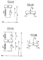
- test device according to the present invention as shown diagrammatically in FIG. 11.
- Each of the suspensions is equipped with a sensor 10, 11, 12, 13 adapted to generate an electrical signal representative of the oscillations of the suspension.
- This sensor may equally be a force sensor, composed for example of a piezoelectric cell, interposed between the suspension spring and the suspended masses or the unsprung masses, a sensitive sensor or relative displacement of suspended masses / unsprung masses,. for example formed of a piezoelectric cell arranged between two turns of the suspension spring, in the case of a coil spring, a force sensor placed on the shock absorber of the suspension, or even an accelerometer placed on the masses not suspended.
- a force sensor composed for example of a piezoelectric cell, interposed between the suspension spring and the suspended masses or the unsprung masses, a sensitive sensor or relative displacement of suspended masses / unsprung masses,.
- a piezoelectric cell arranged between two turns of the suspension spring, in the case of a coil spring, a force sensor placed on the shock absorber of the suspension, or even an accelerometer placed on the masses not suspended.
- the electrical signals delivered by the sensors 10, 11, 12 and 13 are preferably applied to a multiplexing member 20 allowing processing in sequence, wheel by wheel, of the signals from the different sensors.
- each sensor 10, 11, 12, 13 can be associated with a specific processing chain.
- a filter cell 25 which is adapted to retain only the oscillations generated by the unsprung masses of the vehicle and the spring effect of the tire.
- the filtering means 25 may for example have a bandwidth ranging from 9 to 15 Hz.
- the electrical signals filtered by the cell 25 are then applied to processing means 30. At the latter, the electrical signals. are first stored in a memory 35.
- the processing means 30 calculate (step 40) the ratio S 11 / S 12 between two successive extrema of the stored signals.
- the processing means 30 then compare (step 50) the value of the ratios determined previously in step 40 across a predetermined range of values, preferably 1 and 3, to determine whether the ratios established in step 40 are included or not in this range.
- the calculated ratios are eliminated by the processing means 30 since they are considered to be non-significant, and in particular capable of being generated following an excitation of the periodic profile type which cannot be used in the context of the present invention.
- Comparison means 80 then determine the difference existing between each of the reports established by the processing means 30 in step 40 and the average resulting from the means 70.
- step 90 a second average on the basis of the ratio values not eliminated in step 80.
- step 90 The value of this average established by the processing means 30 in step 90 is used to determine in step 95 the value of a parameter representative of the viscous coefficient of friction c of the damper.
- the value of the desired parameter c is determined on the basis of the relationship (32) wherein S 11 / S 12 re p re- feel the mean value established by the processing means 30 in step 90.
- the value of the parameter sought-c can be obtained using a correspondence table between the extrema ratios S 11 / S 12 on the one hand and the value sought of the parameter on the other hand.
- This correspondence table can be defined either using the above-mentioned relation (32) or on the basis of an approximation of the curve defined by this relation in the form of a succession of linear segments of different slopes.
- This alarm detection and display step can consist of comparing the value of the aforementioned parameter c with a threshold value and displaying an alarm when the calculated value of the coefficient of friction c falls below the threshold value, either to be viewed directly analog information representative of the viscous friction coefficient c.
- the parameter representative of the coefficient c can in particular be determined on the basis of extrema which are not successive, by adapting accordingly the relation (32), or the correspondence table used.
- the present invention can in particular be applied for controlling slave suspensions, for example for controlling the hardness of the suspension, in particular for compensation for wear.
- the display means 100 are adapted to deliver specific information for each of the suspensions, either in the form of an alarm indicator in the case of a comparison with a threshold value as previously mentioned, or in the form of an analog display of each of the measured coefficients c.
Landscapes
- Engineering & Computer Science (AREA)
- Mechanical Engineering (AREA)
- Physics & Mathematics (AREA)
- General Physics & Mathematics (AREA)
- General Engineering & Computer Science (AREA)
- Human Computer Interaction (AREA)
- Vehicle Body Suspensions (AREA)
Applications Claiming Priority (2)
| Application Number | Priority Date | Filing Date | Title |
|---|---|---|---|
| FR8515084A FR2588661B1 (fr) | 1985-10-11 | 1985-10-11 | Procede de controle d'une suspension de vehicule par mesure du facteur d'amortissement d'un signal oscillatoire de la suspension et dispositif pour la mise en oeuvre du procede. |
| FR8515084 | 1985-10-11 |
Publications (2)
| Publication Number | Publication Date |
|---|---|
| EP0220985A1 true EP0220985A1 (de) | 1987-05-06 |
| EP0220985B1 EP0220985B1 (de) | 1990-03-28 |
Family
ID=9323740
Family Applications (1)
| Application Number | Title | Priority Date | Filing Date |
|---|---|---|---|
| EP19860402253 Expired - Lifetime EP0220985B1 (de) | 1985-10-11 | 1986-10-10 | Verfahren und Vorrichtung zur Überwachung einer Fahrzeugaufhängung mittels Messung des Dämpfungsfaktors einer Schwingung der Aufhängung |
Country Status (3)
| Country | Link |
|---|---|
| EP (1) | EP0220985B1 (de) |
| DE (1) | DE3669922D1 (de) |
| FR (1) | FR2588661B1 (de) |
Cited By (5)
| Publication number | Priority date | Publication date | Assignee | Title |
|---|---|---|---|---|
| EP0355398A2 (de) * | 1988-08-16 | 1990-02-28 | Nathan Needleman | Elektronisches Stossdämpferprüfgerät |
| EP0650859A1 (de) * | 1993-10-28 | 1995-05-03 | Toyota Jidosha Kabushiki Kaisha | Dämpfungssteuerung mit Schätzung der Temperatur des Stossdämpfers |
| WO2009048347A1 (en) * | 2007-10-10 | 2009-04-16 | Universidade De Trás-Os-Montes E Alto Douro | Continuous monitoring system for application in shock absorbers |
| WO2011121247A1 (fr) | 2010-04-02 | 2011-10-06 | Societe De Technologie Michelin | Procede de caracterisation et d'amelioration du comportement d'un vehicule |
| US20110307125A1 (en) * | 2010-06-14 | 2011-12-15 | Eurocopter | Method of monitoring the effectiveness of a damper, and a device for implementing said method |
Families Citing this family (2)
| Publication number | Priority date | Publication date | Assignee | Title |
|---|---|---|---|---|
| PL3505903T3 (pl) | 2017-12-30 | 2021-04-19 | Emt-Systems Sp. Z O.O. | Sposób wykrywania wad produkcyjnych tłumików hydraulicznych zwłaszcza amortyzatorów hydraulicznych oraz urządzenie do wykrywania wad produkcyjnych tłumików hydraulicznych zwłaszcza amortyzatorów hydraulicznych |
| CN110910531B (zh) * | 2019-10-21 | 2020-10-20 | 同济大学 | 一种基于车载obd信息的路面摩擦系数快速检测方法 |
Citations (3)
| Publication number | Priority date | Publication date | Assignee | Title |
|---|---|---|---|---|
| DE2362661A1 (de) * | 1973-07-09 | 1975-06-26 | Volkswagenwerk Ag | Verfahren zur pruefung der funktionsfaehigkeit von stossdaempfern |
| DE2905931A1 (de) * | 1979-02-16 | 1980-08-28 | Daimler Benz Ag | Vorrichtung zur ueberwachung von stossdaempfern und reifenluftdruck von fahrzeugraedern |
| US4458234A (en) * | 1981-05-14 | 1984-07-03 | Brisard Gerard J | On-board apparatus for monitoring the condition of shock absorbers |
-
1985
- 1985-10-11 FR FR8515084A patent/FR2588661B1/fr not_active Expired
-
1986
- 1986-10-10 EP EP19860402253 patent/EP0220985B1/de not_active Expired - Lifetime
- 1986-10-10 DE DE8686402253T patent/DE3669922D1/de not_active Expired - Lifetime
Patent Citations (3)
| Publication number | Priority date | Publication date | Assignee | Title |
|---|---|---|---|---|
| DE2362661A1 (de) * | 1973-07-09 | 1975-06-26 | Volkswagenwerk Ag | Verfahren zur pruefung der funktionsfaehigkeit von stossdaempfern |
| DE2905931A1 (de) * | 1979-02-16 | 1980-08-28 | Daimler Benz Ag | Vorrichtung zur ueberwachung von stossdaempfern und reifenluftdruck von fahrzeugraedern |
| US4458234A (en) * | 1981-05-14 | 1984-07-03 | Brisard Gerard J | On-board apparatus for monitoring the condition of shock absorbers |
Cited By (13)
| Publication number | Priority date | Publication date | Assignee | Title |
|---|---|---|---|---|
| EP0355398A2 (de) * | 1988-08-16 | 1990-02-28 | Nathan Needleman | Elektronisches Stossdämpferprüfgerät |
| EP0355398A3 (de) * | 1988-08-16 | 1991-07-03 | Nathan Needleman | Elektronisches Stossdämpferprüfgerät |
| EP0650859A1 (de) * | 1993-10-28 | 1995-05-03 | Toyota Jidosha Kabushiki Kaisha | Dämpfungssteuerung mit Schätzung der Temperatur des Stossdämpfers |
| US5555500A (en) * | 1993-10-28 | 1996-09-10 | Toyota Jidosha Kabushiki Kaisha | Oil temperature estimating device for shock absorber, and shock absorber damping force control apparatus using such oil temperature estimating device |
| WO2009048347A1 (en) * | 2007-10-10 | 2009-04-16 | Universidade De Trás-Os-Montes E Alto Douro | Continuous monitoring system for application in shock absorbers |
| FR2958400A1 (fr) * | 2010-04-02 | 2011-10-07 | Michelin Soc Tech | Procede de caracterisation et d'amelioration du comportement d'un vehicule |
| WO2011121247A1 (fr) | 2010-04-02 | 2011-10-06 | Societe De Technologie Michelin | Procede de caracterisation et d'amelioration du comportement d'un vehicule |
| CN102844652A (zh) * | 2010-04-02 | 2012-12-26 | 米其林集团总公司 | 用于表征及改进车辆性能的方法 |
| JP2013524193A (ja) * | 2010-04-02 | 2013-06-17 | コンパニー ゼネラール デ エタブリッスマン ミシュラン | 車両の挙動を特徴付けて向上させる方法 |
| US8938330B2 (en) | 2010-04-02 | 2015-01-20 | Compagnie Generale Des Etablissements Michelin | Method for characterising and improving the behaviour of a vehicle |
| CN102844652B (zh) * | 2010-04-02 | 2016-04-20 | 米其林集团总公司 | 用于表征及改进车辆性能的方法 |
| US20110307125A1 (en) * | 2010-06-14 | 2011-12-15 | Eurocopter | Method of monitoring the effectiveness of a damper, and a device for implementing said method |
| US8532845B2 (en) * | 2010-06-14 | 2013-09-10 | Europcopter | Method of monitoring the effectiveness of a damper, and a device for implementing said method |
Also Published As
| Publication number | Publication date |
|---|---|
| EP0220985B1 (de) | 1990-03-28 |
| DE3669922D1 (de) | 1990-05-03 |
| FR2588661A1 (fr) | 1987-04-17 |
| FR2588661B1 (fr) | 1989-04-14 |
Similar Documents
| Publication | Publication Date | Title |
|---|---|---|
| EP0220115B1 (de) | Verfahren und Vorrichtung zur Überwachung einer Fahrzeugaufhängung mittels Messung des Reibungskoeffizienten des Stossdämpfers | |
| EP1565719B1 (de) | System und verfahren zur stossdämpferdiagnose | |
| EP0220985B1 (de) | Verfahren und Vorrichtung zur Überwachung einer Fahrzeugaufhängung mittels Messung des Dämpfungsfaktors einer Schwingung der Aufhängung | |
| FR2874205A1 (fr) | Procede et dispositif de suspension active d'un aeronef a voilure tournante | |
| FR2719000A1 (fr) | Système de suspension actif, en particulier pour automobiles. | |
| FR2594922A1 (fr) | Procede pour regler la force d'amortissement d'un amortisseur | |
| FR3002204A1 (fr) | Amortisseur instrumente et systeme de suivi de performance comprenant un tel amortisseur. | |
| FR2807512A1 (fr) | Inclinometre a reseau de bragg | |
| GB2307667A (en) | System for inspecting vehicular shock absorber | |
| US5269186A (en) | Apparatus and method for detecting rotational imbalance of vehicle roadwheels | |
| EP0657620B1 (de) | Verfahren und System zur Kontrolle des "Stick-Slip" eines Bohrwerkzeugs | |
| EP0220116B1 (de) | Verfahren und Vorrichtung zum Überwachen einer Fahrzeugaufhängung mittels Messung des Reibungskoeffizienten des Dämpfers | |
| FR2520870A1 (fr) | Dispositif permettant de mesurer la charge repartie sur les moyens de roulement d'un train d'atterrissage d'un aeronef | |
| EP0223653B1 (de) | Verfahren und Vorrichtung zur Überwachung einer Fahrzeugaufhängung mittels Überwachung der Strassenhaftung | |
| EP1571517A1 (de) | Steuerungsverfahren und Vorrichtung für die Dämpfung der Schwingungen eines Hubschraubers | |
| CN112413030A (zh) | 一种减振器阻尼控制和性能评定方法、以此方法优化的减振器和采用此减振器的车辆 | |
| FR3084291B1 (fr) | Dispositif d'amortissement d'un vehicule et procede associe | |
| US2992837A (en) | Vehicle suspension and stabilizing system | |
| FR2957306A3 (fr) | Amortisseur semi-actif de vehicule automobile et procede de commande correspondant | |
| Lozoya-Santos et al. | Fault detection for an automotive MR damper | |
| US4452435A (en) | Apparatus for controlling friction between leaf springs of a laminated leaf spring assembly | |
| Ashmore et al. | Dynamic force measurement vehicle (DFMV) and its application to measuring and monitoring road roughness | |
| EP0483016A1 (de) | Verfahren und Vorrichtung zur Kontrolle des Wirkungsgrades einer Aufhängung in situ | |
| FR2693273A1 (fr) | Procédé et dispositif pour la détermination de l'accélération d'une superstructure de véhicule. | |
| Miletiev et al. | Time and frequency analysis of the vehicle suspension dynamics |
Legal Events
| Date | Code | Title | Description |
|---|---|---|---|
| PUAI | Public reference made under article 153(3) epc to a published international application that has entered the european phase |
Free format text: ORIGINAL CODE: 0009012 |
|
| AK | Designated contracting states |
Kind code of ref document: A1 Designated state(s): DE GB IT |
|
| 17P | Request for examination filed |
Effective date: 19870921 |
|
| 17Q | First examination report despatched |
Effective date: 19881110 |
|
| GRAA | (expected) grant |
Free format text: ORIGINAL CODE: 0009210 |
|
| AK | Designated contracting states |
Kind code of ref document: B1 Designated state(s): DE GB IT |
|
| PG25 | Lapsed in a contracting state [announced via postgrant information from national office to epo] |
Ref country code: IT Free format text: LAPSE BECAUSE OF FAILURE TO SUBMIT A TRANSLATION OF THE DESCRIPTION OR TO PAY THE FEE WITHIN THE PRESCRIBED TIME-LIMIT;WARNING: LAPSES OF ITALIAN PATENTS WITH EFFECTIVE DATE BEFORE 2007 MAY HAVE OCCURRED AT ANY TIME BEFORE 2007. THE CORRECT EFFECTIVE DATE MAY BE DIFFERENT FROM THE ONE RECORDED. Effective date: 19900328 Ref country code: GB Effective date: 19900328 |
|
| REF | Corresponds to: |
Ref document number: 3669922 Country of ref document: DE Date of ref document: 19900503 |
|
| GBV | Gb: ep patent (uk) treated as always having been void in accordance with gb section 77(7)/1977 [no translation filed] | ||
| PLBE | No opposition filed within time limit |
Free format text: ORIGINAL CODE: 0009261 |
|
| STAA | Information on the status of an ep patent application or granted ep patent |
Free format text: STATUS: NO OPPOSITION FILED WITHIN TIME LIMIT |
|
| 26N | No opposition filed | ||
| PGFP | Annual fee paid to national office [announced via postgrant information from national office to epo] |
Ref country code: DE Payment date: 19921121 Year of fee payment: 7 |
|
| PG25 | Lapsed in a contracting state [announced via postgrant information from national office to epo] |
Ref country code: DE Effective date: 19940701 |