EP0220745B1 - Cutting device for wall and floor coverings - Google Patents
Cutting device for wall and floor coverings Download PDFInfo
- Publication number
- EP0220745B1 EP0220745B1 EP86115103A EP86115103A EP0220745B1 EP 0220745 B1 EP0220745 B1 EP 0220745B1 EP 86115103 A EP86115103 A EP 86115103A EP 86115103 A EP86115103 A EP 86115103A EP 0220745 B1 EP0220745 B1 EP 0220745B1
- Authority
- EP
- European Patent Office
- Prior art keywords
- cutting
- grooves
- counterblade
- carrying surface
- cutting device
- Prior art date
- Legal status (The legal status is an assumption and is not a legal conclusion. Google has not performed a legal analysis and makes no representation as to the accuracy of the status listed.)
- Expired - Lifetime
Links
Images


Classifications
-
- B—PERFORMING OPERATIONS; TRANSPORTING
- B26—HAND CUTTING TOOLS; CUTTING; SEVERING
- B26B—HAND-HELD CUTTING TOOLS NOT OTHERWISE PROVIDED FOR
- B26B29/00—Guards or sheaths or guides for hand cutting tools; Arrangements for guiding hand cutting tools
Definitions
- the present invention relates to a cutting device for wall and floor coverings.
- Guide devices for cutting or trimming a paper wallpaper web or a similar material are known.
- a guide device is known from DE-A 2 822 844, for example, which consists of a profile which on the one hand defines a bearing surface for support on a wall and on the other hand a support surface for the web to be cut and has a guide device for a knife.
- a groove provided in the support surface serves as the guide device.
- DE-U 7 804 744 also describes a cutting ruler intended for cutting sheet material, such as wallpaper or carpet webs, to length, consisting of an extruded profile section with an essentially T-shaped cross section, which, in a central arrangement on a predominantly flat profile flange, has one for this purpose has vertical legs which are flat on the broad side and whose leg height corresponds to approximately half the flange width and wherein a cutting groove extending parallel to the longitudinal direction of the profile is provided on the flange outer surface, approximately centrally on at least one flange half.
- the above-mentioned guide devices have the disadvantage that they all tend, due to their T-shaped design, to be pressed into soft wall material in particular. In addition, they are not very stable.
- the web material is generally cut to the required dimensions with sharp knives. Electric knives or scissors are also used to cut to size.
- DE-A 1 553 763 describes an electrically drivable pair of scissors with two legs that carry the scissor blades and are mounted in the scissors housing, of which the first leg coupled with an electric drive can be rotated about a scissor axis and the second is fixedly mounted in the housing.
- DE-A 2 130 043 also discloses an electric pair of scissors with a housing in which an electrically actuable motor, a usually stationary counterblade and a second blade are mounted, the latter of which can be oscillated by the motor, and with one Drive means connecting the motor to the second blade to swing the second blade in and out of cooperative cutting engagement with the usually fixed counter blade.
- the electrical cutting devices mentioned are not particularly suitable for cutting material webs, they result in an uneven cut.
- the object of the present invention is to provide a cutting device for wall and floor coverings according to the preamble of claim 1, which allows a better fit of the device even on soft walls and with which a clean and uniform cut can be achieved without great effort.
- the object of the invention is achieved by the interaction of the electric scissors with the shear blade or counterblade directed towards the handle and the width of the cutting grooves in the cutting rail, which width is dimensioned to the width of the shear blade or the counterblade.
- This enables the scissors to be easily guided in the cutting rail.
- the scissors can be guided in the cutting groove without great pressure and the special design of the scissors ensures a clean and even cut.
- the cutting rail has a cross section in the form of a right-angled triangle.
- the cutting rail has a cross section in the form of a right-angled triangle.
- rooms with non-rectangular corners that have a different cross-sectional shape.
- the plastic extruded profile part from which the cutting rail is made can be equipped with internal reinforcing ribs for better stiffening, which can for example run between the support surface and the longer of the two support surfaces.
- the wall covering when cut in this cutting groove is given a length which, when the cutting rail is placed in the corners of the room, extends exactly into that Cut edge of the corner of the room is sufficient. This ensures that the wall covering at the cut edge of the corner of the room is precisely nudged or closed.
- the remaining cutting grooves which have a greater distance from the cut edge of the support surface and the support surface, are provided for the case that should extend beyond the cut edge of the corner of the room, which is useful, for example, if the same wall covering is to be attached to both sides of the cut edge .
- one of the two wall coverings is expediently allowed to run over the cut edge and then a second, precisely cut wall covering is papered over from the other side.
- the other cutting grooves can also be used if a door frame or skirting board is to be overlapped with paper.
- the cut edge of the two support surfaces is preferably rounded. This makes it possible to paper even slightly uneven edges, damage to the cut edge is avoided and the cutting rail lies flat against the wall, even if the corners of the room are not exactly at right angles.
- the depth t of the cutting grooves is less than the height h of the stationary counterblade up to its stop on the scissor housing.
- the stationary counterblade lies on the bottom of the cutting groove during the cutting process, while the stop of the blades on the housing is exposed and does not touch the support surface. Damage to the wall covering material to be cut is thereby avoided and, with little friction of the blades on the cutting rail, the electrical scissors can be easily guided in the cutting groove. Since most wall covering materials are relatively thin, it is preferred that the depth of the cutting grooves is about 0.5 to 2 mm less than the height of the stationary counterblade.
- One of the two supporting surfaces of the plastic extruded profile can be extended beyond the point of intersection with the supporting surface, which results in a projection in the form of a projecting nose which prevents contact between the wallpaper protruding during cutting and the wall.
- a protruding piece of wallpaper for example coated with paste, sticks to the nose after cutting without touching the wall and can be easily removed after removing the cutting bar.
- the cutting rail since it is not cut with a conventional wallpaper knife, can be made much thinner than the previously known cutting rails, it does not require any metal guide parts. This makes it much lighter in weight, which leads to less effort for holding the cutting rail.
- the plastic extruded profile of the cutting rail can be foamed with a light foam to increase stability.
- the carrying surface of the cutting rail can be raised. It is thereby achieved that the cutting grooves are moved more from the inclined position into the horizontal position, whereby an ergonomically more favorable cutting position of the electric scissors is achieved in a more horizontal position. This also makes it easier to move the hand that holds the scissors past the hand that guides the cutting rail.
- the electric scissors consist of a housing with a drive motor which causes one of the two blades to oscillate, while the other blade is designed as a stationary counterblade against which the movable blade swings.
- Such scissors, the blades and thus the direction of cut away from the housing are known. So far they have been used to a certain extent for cutting paper and the like, but have so far not been able to assert themselves for cutting wallpapers.
- the cutting edge of the stationary counterblade be at an angle of approximately 20 to 50 ° , particularly preferably of approximately 30 to 40 ° , to the longitudinal axis of the electrical scissors, ie to Longitudinal axis of the scissor housing is attached.
- the shear blade is rotatable about an axis which is attached centrally or eccentrically in the parabolic or similarly designed shear blade.
- the cutting blade ie the cutting sharp part of the shear blade, preferably lies within the area between the axis and the drive of the shear blade.
- the electric scissors have a drive motor in a housing known per se, which drives a shear blade, the cutting direction of which, as seen from the shear blade or from the stationary counterblade, lies in the direction of the housing.
- the center of gravity of the driven shear blade is within the housing.
- the pivot point of the driven shear blade lies outside the housing at the outer end of the shear blade.
- Such a cutting device is also suitable for cutting floor coverings, for example for cutting carpets, carpeting, linoleum and the like.
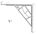
- the cutting rail 10 consists of a plastic extruded profile 12 in the form of a right-angled triangle.
- the support surfaces 14, 16 which bear against the right angle of the triangle and with which the cutting rail 10 is placed against the wall and the ceiling of the room to be papered in such a way that the right angle lies in the angle formed by the wall and the ceiling of the room, support the cutting rail 10 against the wall and ceiling.
- a total of three cutting grooves 20, 22, 24, which are designed as slot-like rectangular recesses in the support surface 18, are let in on the support surface 18 opposite the right angle.
- the distance of the cutting groove 20 from the cutting edge 26 of the support surface 18 and the support surface 14 is equal to the length of the support surface 14, which causes a wall covering cut in the cutting groove 20 to extend exactly into the corner of the room.
- the remaining cutting grooves 22, 24 have a somewhat greater distance from the cutting edge 26, a wall covering cut off in these cutting grooves overlaps the corner of the room, which is advantageous if several walls colliding in one corner of the room are to be equipped with the same wall covering.
- the cutting grooves are therefore closer to the cutting edge 28 of the support surface 18 and the shorter support surface 16 than to the cutting edge 26.
- the plastic extruded profile 12 has a rectangular cross section with an aspect ratio of 3: 4: 5.
- the plastic extruded profile is reinforced by inner reinforcing ribs 30 which run from the support surface 18 to the two support surfaces 14, 16.
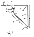
- FIG. 7 A further embodiment of the cutting rail is shown in FIG. 7, in which one of the two support surfaces 14, 15 is extended beyond the point of intersection with the support surface 18 to form a projecting nose 29.
- the support surface 18 also has a raised edge 32 which protrudes from the triangular cross section of the cutting rail 10. A protruding piece of wallpaper coated with paste will stick to the nose after cutting without touching the wall and can be easily removed after removing the cutting bar.
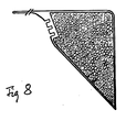
- the plastic extruded profile of the cutting rail can be foamed with a light foam to increase stability, as shown in FIG. 8.
- the electric scissors 40 consist of an elongated housing 50, which is designed as a handle, in which a drive motor 46 is arranged.
- the drive motor 46 is connected via a transmission member, which converts the rotary movement of the motor into a pivoting movement, with the driven shear blade 44, which is pivotable up and down about a pivot point 48.
- the pivoting movement is carried out against the stationary counter blade 42, which results in a cutting effect.
- the entire structure of the housing 50 with drive motor 46 and transmission member corresponds to the already known commercially available electrical scissors (see Fig. 3-6).
- the design of the scissor blades differs from the construction of the known scissors. While in the known scissors, the blades are attached to the housing so that the scissors are moved away from the operator's body in a pushing motion, are in the present electric scissors, the scissor blades are arranged so that the cutting movement takes place toward the operator's body.
- the scissor blades are attached to one side of the housing at an angle of approximately 20 to 50 ° to the longitudinal axis of the housing, preferably at an angle of approximately 30 to 40 °.
- the longitudinal axis of the housing is understood to mean the axis which runs parallel to the longest dimension of the housing. It can be seen from FIG.
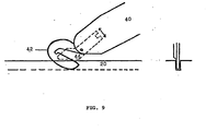
- FIG. 9 shows a further embodiment of an electric scissors for "backward cutting".
- the pivot point 48 of the driven shear blade 44 lies within the housing 50.
- the driven shear blade 44 can be designed in any shape, it is no longer dependent on the position of the pivot point.
- the size and angular position of the driven shear blade 44 and the stationary counterblade 42 can be freely selected from one another. This gives a more free choice of construction options.
- the cutting device according to the invention for wall and floor coverings consists of a cutting rail and of an electric scissors which can be inserted into the cutting rail, the cutting rail consisting of a plastic extruded profile section with a triangular cross section and the electric scissors having cutting blades, the cutting direction of which indicates the body of the operator.
- the combined device enables a clean cut without great effort, even under difficult working conditions.
Description
Die vorliegende Erfindung betrifft eine Schneidvorrichtung für Wand- und Bodenbeläge.The present invention relates to a cutting device for wall and floor coverings.
Führungsvorrichtungen zum Zu- bzw. Beschneiden einer Papiertapetenbahn oder eines ähnlichen Materials sind bekannt. So ist beispielsweise aus der DE-A 2 822 844 eine solche Führungsvorrichtung bekannt, die aus einem Profil besteht, das einerseits eine Anlageoberfläche zum Abstützen an einer Wand und andererseits eine Tragoberfläche für die zuzuschneidende Bahn definiert und eine Führungsvorrichtung für ein Messer aufweist. Als Führungsvorrichtung dient eine in der Tragoberfläche vorgesehene Rille.Guide devices for cutting or trimming a paper wallpaper web or a similar material are known. Such a guide device is known from DE-A 2 822 844, for example, which consists of a profile which on the one hand defines a bearing surface for support on a wall and on the other hand a support surface for the web to be cut and has a guide device for a knife. A groove provided in the support surface serves as the guide device.
Auch das DE-U 7 804 744 beschreibt ein zum Ablängen von bahnförmigem Material, wie Tapeten-oder Teppichbahnen, bestimmtes Schneidlineal, bestehend aus einem Strangprofil-Abschnitt mit im wesentlichen T-förmigem Querschnitt, welches in mittiger Anordnung an einem überwiegend ebenflächigen Profilflansch einen hierzu senkrechten, breitseitig ebenflächigen Schenkel aufweist, dessen Schenkelhöhe etwa der halben Flanschbreite entspricht und wobei an der Flanschaußenfläche, etwa mittig auf mindestens einer Flanschhälfte, eine sich parallel zur Profillängsrichtung erstreckende Schneidrille vorgesehen ist.DE-U 7 804 744 also describes a cutting ruler intended for cutting sheet material, such as wallpaper or carpet webs, to length, consisting of an extruded profile section with an essentially T-shaped cross section, which, in a central arrangement on a predominantly flat profile flange, has one for this purpose has vertical legs which are flat on the broad side and whose leg height corresponds to approximately half the flange width and wherein a cutting groove extending parallel to the longitudinal direction of the profile is provided on the flange outer surface, approximately centrally on at least one flange half.
Die genannten Führungsvorrichtungen haben den Nachteil, daß sie alle infolge ihrer T-förmigen Ausbildung dazu neigen, sich insbesondere in weiches Wandmaterial einzudrücken. Außerdem sind sie wenig standfest.The above-mentioned guide devices have the disadvantage that they all tend, due to their T-shaped design, to be pressed into soft wall material in particular. In addition, they are not very stable.
Das Bahnmaterial wird im allgemeinen mit scharfen Messern in die erforderlichen Maße geschnitte. Es sind auch elektrische Messer oder Scheren in Gebrauch, mit denen das Zuschneiden erfolgen kann.The web material is generally cut to the required dimensions with sharp knives. Electric knives or scissors are also used to cut to size.
So beschreibt beispielsweise die DE-A 1 553 763 eine elektrisch antreibbare Schere mit zwei die Scherenschneiden tragenden, im Scherengehäuse gelagerten Schenkeln, von denen der erste mit einem elektrischen Antrieb gekuppelte Schenkel um eine Scherenachse drehbar und der zweite fest im Gehäuse gelagert ist.For example, DE-A 1 553 763 describes an electrically drivable pair of scissors with two legs that carry the scissor blades and are mounted in the scissors housing, of which the first leg coupled with an electric drive can be rotated about a scissor axis and the second is fixedly mounted in the housing.
Ein ähnliches elektrisches Schergerät mit einem feststehenden und einem oszillierend antreibbaren Schermesser ist in der DE-A 2 015 846 beschrieben.A similar electric shaving device with a fixed and an oscillating drivable shear knife is described in DE-A 2 015 846.
Auch die DE-A 2 130 043 offenbart eine elektrische Schere mit einem Gehäuse, in welchem ein elektrisch betätigbarer Motor, eine gewöhnlich ortsfeste Gegenklinge und eine zweite Klinge angebracht sind, von denen die letztere von dem Motor in Schwingbewegungen versetzt werden kann, und mit einer Antriebseinrichtung, welche den Motor mit der zweiten Klinge verbindet, um die zweite Klinge in und außer zusammenarbeitenden Schneideingriff mit der gewöhnlich ortsfesten Gegenklinge zu schwingen.DE-A 2 130 043 also discloses an electric pair of scissors with a housing in which an electrically actuable motor, a usually stationary counterblade and a second blade are mounted, the latter of which can be oscillated by the motor, and with one Drive means connecting the motor to the second blade to swing the second blade in and out of cooperative cutting engagement with the usually fixed counter blade.
Die genannten elektrischen Schneidgeräte eignen sich nicht besonders zum Zuschneiden von Materialbahnen, sie ergeben einen ungleichmäßigen Schnitt.The electrical cutting devices mentioned are not particularly suitable for cutting material webs, they result in an uneven cut.
Es wurde gefunden, daß der ungleichmäßige Schnitt u.a. dadurch bewirkt wird, daß die Schneidgeräte nach vorn schneiden, wie es bei einer Schere üblich ist, und am Material hängen bleiben. Schneidet man jedoch rückwärts, wie es mit einem Messer üblich ist, so wird der Schnitt wesentlich gleichmäßiger.It has been found that the uneven cut i.a. This causes the cutters to cut forward, as is common with scissors, and stick to the material. However, if you cut backwards, as is usual with a knife, the cut becomes much more even.
Aufgabe der vorliegenden Erfindung ist es, eine Schneidvorrichtung für Wand- und Bodenbeläge entsprechend dem Oberbegriff des Anspruchs 1 zu schaffen, die ein besseres Anliegen der Vorrichtung auch an weichen Wänden ermöglicht und mit der sich ohne großen Kraftaufwand ein sauberer und gleichmäßiger Schnitt erzielen läßt.The object of the present invention is to provide a cutting device for wall and floor coverings according to the preamble of claim 1, which allows a better fit of the device even on soft walls and with which a clean and uniform cut can be achieved without great effort.
Gelöst wird diese Aufgabe dadurch, daß die Schneidvorrichtung aus einer elektrischen Schere (40) besteht, wobei
- a) die Schneidschiene (10) aus einem KunststoffStrangprofilabschnitt (12) mit einem dreieckförmigen Querschnitt mit zwei kürzeren Stützoberflächen (14, 16) und einer längeren Tragoberfläche (18) besteht, und die Tragoberfläche (18) drei oder mehr Schneidrillen (20, 22, 24) aufweist, die parallel zu den Schnittkanten (26, 28) der Stützoberflächen (14, 16) und der Tragoberflächen (18) verlaufen, wobei der Abstand einer der Schneidrillen (20) von der Schnittkante (26) der Tragoberfläche (18) und der Stützoberfläche (14) gleich der Länge der Stützoberfläche (14) ist und die übrigen Schneidrillen (22, 24) einen größeren Abstand aufweisen, und
- b) die elektrische Schere (40) an einem an sich bekannten Gehäuse (50) mit Antriebsmotor (46) eine ortsfeste Gegenklinge (42) und eine vom Antriebsmotor (46) angetriebene Scherklinge (44) aufweist, deren Schneidrichtung, von der beweglichen Scherklinge (44) bzw. der ortsfesten Gegenklinge (42) aus gesehen, in Richtung zum Gehäuse (50) liegt, wobei die elektrische Schere (40) mit ihrer ortsfesten Gegenklinge (42) in einer der Schneidrillen (20, 22, 24) geführt ist, und die Anordnung der Scherklingen (42, 44) derart ist, daß die Schneidbewegung in ziehender Bewegung zum Körper der Bedienungsperson hin erfolgt,
- c) die Breite der Gegenklinge (42) an die Breite der Schneidrillen (20, 22, 24) angepaßt ist.
- a) the cutting rail (10) consists of a plastic extruded section (12) with a triangular cross section with two shorter support surfaces (14, 16) and a longer supporting surface (18), and the supporting surface (18) three or more cutting grooves (20, 22, 24) which run parallel to the cut edges (26, 28) of the support surfaces (14, 16) and the support surfaces (18), the distance between one of the cutting grooves (20) and the cut edge (26) of the support surface (18) and the support surface (14) is equal to the length of the support surface (14) and the other cutting grooves (22, 24) are at a greater distance, and
- b) the electric scissors (40) on a housing (50) with drive motor (46) known per se has a stationary counterblade (42) and a shear blade (44) driven by the drive motor (46), the cutting direction of which is dependent on the movable shear blade ( 44) or the stationary counterblade (42), in the direction of the housing (50), the electric scissors (40) with their stationary counterblade (42) being guided in one of the cutting grooves (20, 22, 24), and the arrangement of the shear blades (42, 44) is such that the cutting movement takes place in a pulling movement towards the body of the operator,
- c) the width of the counter blade (42) is adapted to the width of the cutting grooves (20, 22, 24).
Die Lösung der erfindungsgemäßen Aufgabe gelingt durch das Zusammenwirken der elektrischen Schere mit der zum Griff hin gerichteten Scherklinge bzw. Gegenklinge und der auf die Breite der Scherklinge bzw. der Gegenklinge bemessenen Breite der Schneidrillen in der Schneidschiene. Dadurch wird eine leichte Führung der Schere in der Schneidschiene möglich. Die Schere kann ohne großen Druck in der Schneidrille geführt werden und durch die spezielle Ausgestaltung der Schere wird ein sauberer und gleichmäßiger Schnitt erzielt.The object of the invention is achieved by the interaction of the electric scissors with the shear blade or counterblade directed towards the handle and the width of the cutting grooves in the cutting rail, which width is dimensioned to the width of the shear blade or the counterblade. This enables the scissors to be easily guided in the cutting rail. The scissors can be guided in the cutting groove without great pressure and the special design of the scissors ensures a clean and even cut.
Für die Ausstattung normaler Räume mit Wandbelägen ist es im allgemeinen bevorzugt, daß die Schneidschiene einen Querschnitt in Form eines rechtwinkligen Dreiecks aufweist. Es sind aber auch Ausführungsformen für Räume mit nicht rechtwinklig gestalteten Ecken denkbar, die eine andere Querschnittsform aufweisen.For equipping normal rooms with wall coverings, it is generally preferred that the cutting rail has a cross section in the form of a right-angled triangle. However, there are also conceivable embodiments for rooms with non-rectangular corners that have a different cross-sectional shape.
Das Kunststoff-Strangprofilteil, aus dem die Schneidschiene besteht, kann zur besseren Versteifung mit inneren Verstärkungsrippen ausgestattet sein, die beispielsweise zwischen der Tragoberfläche und der längeren der beiden Stützoberflächen verlaufen können.The plastic extruded profile part from which the cutting rail is made can be equipped with internal reinforcing ribs for better stiffening, which can for example run between the support surface and the longer of the two support surfaces.
Da die eine der Schneidrillen einen Abstand von der Schnittkante der Tragoberfläche und einer der Stützoberflächen hat, der gleich der Länge der längeren Stützoberfläche ist, erhält der Wandbelag beim Abschneiden in dieser Schneidrille genau eine Länge, die beim Anlegen der Schneidschiene in Zimmerecken bis genau in die Schnittkante der Zimmerecke reicht. Damit wird ein genaues Anstossen bzw. Abschließen des Wandbelags an der Schnittkante der Zimmerecke erzielt. Die übrigen Schneidrillen, die einen größeren Abstand von der Schnittkante der Tragoberfläche und der Stützoberfläche aufweisen, sind für den Fall vorgesehen, daß über die Schnittkante der Zimmerecke hinausreichen soll, was beispielsweise zweckmäßig ist, wenn an beiden Seiten der Schnittkante der gleiche Wandbelag angebracht werden soll. In solchen Fällen läßt man zweckmäßigerweise einen der beiden Wandbeläge über die Schnittkante hinweg verlaufen und tapeziert dann einen zweiten genau zugeschnittenen Wandbelag von der anderen Seite her darüber. Aber auch, wenn eine Türzarge oder Fußleiste überlappend tapeziert werden soll, können die übrigen Schneidrillen verwendet werden.Since the one of the cutting grooves is at a distance from the cut edge of the support surface and one of the support surfaces, which is equal to the length of the longer support surface, the wall covering when cut in this cutting groove is given a length which, when the cutting rail is placed in the corners of the room, extends exactly into that Cut edge of the corner of the room is sufficient. This ensures that the wall covering at the cut edge of the corner of the room is precisely nudged or closed. The remaining cutting grooves, which have a greater distance from the cut edge of the support surface and the support surface, are provided for the case that should extend beyond the cut edge of the corner of the room, which is useful, for example, if the same wall covering is to be attached to both sides of the cut edge . In such cases, one of the two wall coverings is expediently allowed to run over the cut edge and then a second, precisely cut wall covering is papered over from the other side. The other cutting grooves can also be used if a door frame or skirting board is to be overlapped with paper.
Die Schnittkante der beiden Stützoberflächen ist vorzugsweise abgerundet. Dadurch wird es möglich, auch etwas ungleichmäßig verlaufende Kanten sauber zu tapezieren, außerdem wird eine Beschädigung der Schnittkante vermieden und erreicht, daß die Schneidschiene plan an der Wand anliegt, auch wenn die Zimmerecken nicht genau rechtwinklig verlaufen.The cut edge of the two support surfaces is preferably rounded. This makes it possible to paper even slightly uneven edges, damage to the cut edge is avoided and the cutting rail lies flat against the wall, even if the corners of the room are not exactly at right angles.
Die Tiefe t der Schneidrillen ist in einer bevorzugten Ausführungsform der vorliegenden Erfindung geringer als die Höhe h der ortsfesten Gegenklinge bis zu ihrem Anschlag am Scherengehäuse. Bei einer solchen Ausführungsform liegt die ortsfeste Gegenklinge während des Schneidvorgangs auf dem Boden der Schneidrille auf, während der Anschlag der Klingen am Gehäuse frei liegt und die Tragoberfläche nicht berührt. Dadurch wird eine Beschädigung des zu schneidenden Wandbelagmaterials vermieden und bei geringer Reibung der Klingen an der Schneidschiene eine leichte Führung der elektrischen Schere in der Schneidrille ermöglicht. Da die meisten Wandbelagsmaterialien relativ dünn sind, ist es bevorzugt, daß die Tiefe der Schneidrillen um etwa 0,5 bis 2 mm geringer ist als die Höhe der ortsfesten Gegenklinge.In a preferred embodiment of the present invention, the depth t of the cutting grooves is less than the height h of the stationary counterblade up to its stop on the scissor housing. In such an embodiment, the stationary counterblade lies on the bottom of the cutting groove during the cutting process, while the stop of the blades on the housing is exposed and does not touch the support surface. Damage to the wall covering material to be cut is thereby avoided and, with little friction of the blades on the cutting rail, the electrical scissors can be easily guided in the cutting groove. Since most wall covering materials are relatively thin, it is preferred that the depth of the cutting grooves is about 0.5 to 2 mm less than the height of the stationary counterblade.
Eine der beiden Stützoberflächen des Kunststoff-Strangprofils kann über den Schnittpunkt mit der Tragoberfläche hinaus verlängert sein, wodurch sich ein Vorsprung in Form einer vorspringenden Nase ergibt, der eine Berührung zwischen der beim Schneiden überstehenden Tapete und der Wand verhindert. Ein überstehendes, beispielsweise mit Kleister bestrichenes Tapetenstück bleibt nach dem Abschneiden an der Nase kleben, ohne die Wand zu berühren und kann nach dem Abnehmen der Schneidschiene leicht entfernt werden.One of the two supporting surfaces of the plastic extruded profile can be extended beyond the point of intersection with the supporting surface, which results in a projection in the form of a projecting nose which prevents contact between the wallpaper protruding during cutting and the wall. A protruding piece of wallpaper, for example coated with paste, sticks to the nose after cutting without touching the wall and can be easily removed after removing the cutting bar.
Die Schneidschiene kann, da sie nicht mit einem üblichen Tapetenmesser geschnitten wird, wesentlich dünner als die bisher bekannten Schneidschienen ausgeführt werden, sie benötigt keine Führungsteile aus Metall. Dadurch wird sie wesentlich leichter an Gewicht, was zu einem geringeren Kraftaufwand für das Halten der Schneidschiene führt.The cutting rail, since it is not cut with a conventional wallpaper knife, can be made much thinner than the previously known cutting rails, it does not require any metal guide parts. This makes it much lighter in weight, which leads to less effort for holding the cutting rail.
Das Kunststoff-Strangprofil der Schneidschiene kann zur Erhöhung der Stabilität mit einem Leichtschaum ausgeschäumt sein.The plastic extruded profile of the cutting rail can be foamed with a light foam to increase stability.
Die Tragoberfläche der Schneidschiene kann in einer weiteren Ausführungsform der Erfindung erhaben gewölbt sein. Dadurch wird erreicht, daß die Schneidrillen aus der schrägen Lage mehr in die waagerechte Lage gerückt werden, wodurch eine ergonomisch günstigere Schneidhaltung der elektrischen Schere in einer mehr waagerechten Lage erzielt wird. Auch wird das Vorbeiführen der Hand, die die Schere hält, an der Hand, die die Schneidschiene führt, dadurch erleichtert.In a further embodiment of the invention, the carrying surface of the cutting rail can be raised. It is thereby achieved that the cutting grooves are moved more from the inclined position into the horizontal position, whereby an ergonomically more favorable cutting position of the electric scissors is achieved in a more horizontal position. This also makes it easier to move the hand that holds the scissors past the hand that guides the cutting rail.
Es ist weiterhin möglich, die Tragoberfläche so abzuwinkeln, daß eine erhöhte Kante auf ihr entsteht, wobei die Schneidrillen in dem Gebiet liegen, das einen flacheren Winkel zur Wand aufweist. Auch dadurch werden die oben diskutierten Vorteile erreicht.It is also possible to bend the support surface so that a raised edge is formed on it, the cutting grooves being in the area which has a flatter angle to the wall. This also achieves the advantages discussed above.
Die elektrische Schere besteht aus einem Gehäuse mit einem Antriebsmotor, der eine der beiden Klingen in eine schwingende Bewegung versetzt, während die andere Klinge als ortsfeste Gegenklinge ausgebildet ist, gegen die die bewegliche Klinge schwingt. Solche Scheren, deren Klingen und damit auch die Schnittrichtung vom Gehäuse weg weisen, sind bekannt. Sie sind bisher zwar schon bis zu einem gewissen Grad zum Schneiden von Papier und dergl. benutzt worden, haben sich aber zum Schneiden von Tapeten bisher nicht durchsetzen können.The electric scissors consist of a housing with a drive motor which causes one of the two blades to oscillate, while the other blade is designed as a stationary counterblade against which the movable blade swings. Such scissors, the blades and thus the direction of cut away from the housing are known. So far they have been used to a certain extent for cutting paper and the like, but have so far not been able to assert themselves for cutting wallpapers.
Gründliche Untersuchungen haben ergeben, daß dies u.a. darauf zurückzuführen ist, daß elektrische Scheren beim Schneiden von Tapeten in schiebender Richtung leicht an Unebenheiten an den Schneidrillen, wie z.B. Tapeten- oder Klebstoffreste, oder an Stauchungen der Tapeten selbst, hängen bleiben und dadurch einen ungleichmäßigen Schnitt ergeben. Die elektrische Schere neigt beim Schieben auch zum Verkanten, wodurch sie ebenfalls leicht an Unebenheiten hängen bleibt.Thorough research has shown that this includes is to be attributed to the fact that when cutting wallpapers in the pushing direction, electric scissors easily have bumps on the cutting grooves, e.g. Remnants of wallpaper or adhesive, or on upholstery of the wallpaper itself, get stuck and result in an uneven cut. The electric scissors also tend to tilt when pushed, which means that they also easily get caught on bumps.
Überraschenderweise läßt sich dieser Nachteil der Kombination aus Schneidschiene und elektrischer Schere dadurch vermeiden, daß die Schneidrichtung der elektrischen Schere so umgekehrt wird, daß nicht mehr in Richtung vom Körper der benutzenden Person weg geschnitten wird, sondern in Richtung zum Körper hin. Dazu muß die elektrische Schere so gestaltet werden, daß die Schneidrichtung der beweglichen Klinge vom Schwenkpunkt der beweglichen Scherklinge aus gesehen in Richtung zum Gehäuse liegt. Außerdem ist es erforderlich, die Breite. der Scherklingen an die Breite der Schneidrillen in der Schneidschiene anzupassen. Mit einer solchen Vorrichtung läßt sich ein einfacher und glatter Schnitt erzielen, der selbst bei nassen Tapeten, die sehr zum Kleben bzw. Reißen neigen, ohne Schwierigkeiten ausführbar ist.Surprisingly, this disadvantage of the combination of cutting rail and electric scissors can be avoided by reversing the cutting direction of the electric scissors so that cutting is no longer carried out in the direction away from the body of the person using it, but towards the body. For this purpose, the electric scissors must be designed so that the cutting direction of the movable blade is from the pivot point of the movable shear blade towards the housing. It also requires the width. adapt the shear blades to the width of the cutting grooves in the cutting rail. With such a device, a simple and smooth cut can be achieved, even with nas Sen wallpapers that are very prone to sticking or tearing, can be carried out without difficulty.
Um beim Schneidvorgang eine möglichst bequeme Haltung der elektrischen Schere zu ermöglichen, ist es bevorzugt, daß die Schneide der ortsfesten Gegenklinge in einem Winkel von etwa 20 bis 50°, besonders bevorzugt von etwa 30 bis 40°, zur Längsachse der elektrischen Schere, d.h. zur Längsachse des Scherengehäuses, angebracht ist. Die Scherklinge ist um eine Achse drehbar, die zentral oder exzentrisch in der parabelförmig oder ähnlich gestalteten Scherklinge angebracht ist. Die Schneidklinge, d.h. der schneidende scharfe Teil der Scherklinge, liegt vorzugsweise innerhalb der Fläche zwischen der Achse und dem Antrieb der Scherklinge.In order to enable the electrical scissors to be held as conveniently as possible during the cutting process, it is preferred that the cutting edge of the stationary counterblade be at an angle of approximately 20 to 50 ° , particularly preferably of approximately 30 to 40 ° , to the longitudinal axis of the electrical scissors, ie to Longitudinal axis of the scissor housing is attached. The shear blade is rotatable about an axis which is attached centrally or eccentrically in the parabolic or similarly designed shear blade. The cutting blade, ie the cutting sharp part of the shear blade, preferably lies within the area between the axis and the drive of the shear blade.
Die elektrische Schere weist einen Antriebsmotor in einem an sich bekannten Gehäuse auf, der eine Scherklinge antreibt, deren Schneidrichtung, von der Scherklinge bzw. von der ortsfesten Gegenklinge aus gesehen, in Richtung zum Gehäuse hin liegt. In einer Ausführungsform liegt der Schwerpunkt der angetriebenen Scherklinge innerhalb des Gehäuses.The electric scissors have a drive motor in a housing known per se, which drives a shear blade, the cutting direction of which, as seen from the shear blade or from the stationary counterblade, lies in the direction of the housing. In one embodiment, the center of gravity of the driven shear blade is within the housing.
In einer weiteren Ausführungsform liegt der Schwenkpunkt der angetriebenen Scherklinge außerhalb des Gehäuses am äußeren Ende der Scherklinge.In a further embodiment, the pivot point of the driven shear blade lies outside the housing at the outer end of the shear blade.
Es wurde gefunden, daß sich eine solche Schneidvorrichtung auch zum Schneiden von Bodenbelägen eignet, wie beispielsweise zum Schneiden von Teppichen, Auslegware, Linoleum und dergl.It has been found that such a cutting device is also suitable for cutting floor coverings, for example for cutting carpets, carpeting, linoleum and the like.
Die Erfindung wird nachfolgend anhand der Figuren beispielhaft näher erläutert, wobei alle in der Figurenbeschreibung enthaltenen Merkmale als erfindungswesentlich angesehen werden.The invention is explained in more detail below by way of example with reference to the figures, all features contained in the description of the figures being regarded as essential to the invention.
- Fig. 1 zeigt eine Schneidschiene mit insgesamt drei Schneidrillen im Schnitt;Fig. 1 shows a cutting rail with a total of three cutting grooves in section;
- Fig. 2 zeigt eine andere Ausführungsform der Schneidschiene mit Verstärkungsrippen im Schnitt;Fig. 2 shows another embodiment of the cutting rail with reinforcing ribs in section;
- Fig. 3 zeigt eine elektrische Schere in einer Gesamtansicht von der Seite;Fig. 3 shows an electric scissors in an overall view from the side;
- Fig. 4 zeigt die bewegliche Scherklinge in einer Seitenansicht;Fig. 4 shows the movable shear blade in a side view;
- Fig. 5 zeigt den Schneidvorgang mit der elektrischen Schere, die in der Schneidrille geführt wird;Fig. 5 shows the cutting process with the electric scissors, which is performed in the cutting groove;
- Fig. 6 zeigt die Ansicht der Fig. 5 in einem seitlichen Schnitt;Fig. 6 shows the view of Fig. 5 in a side section;
- Fig. 7 zeigt eine Schnittansicht einer Schneidschiene mit einer erhöhten Kante auf der Tragoberfläche; undFig. 7 shows a sectional view of a cutting rail with a raised edge on the support surface; and
- Fig. 8 zeigt eine ähnliche Schnittansicht einer Schneidschiene wie die Fig. 7 mit einer im Inneren mit Leichtschaum ausgeschäumten Verstärkung.FIG. 8 shows a similar sectional view of a cutting rail as in FIG. 7 with a reinforcement foamed inside with light foam.
- Fig. 9 zeigt eine Ausführungsform der elektrischen Schere.9 shows an embodiment of the electric scissors.
Die Schneidschiene 10 besteht aus einem Kunststoff-Strangprofil 12 in Form eines rechtwinkligen Dreiecks. Die am rechten Winkel des Dreiecks anliegenden Stützoberflächen 14, 16, mit denen die Schneidschiene 10 so an die Wand und die Decke des zu tapezierenden Raumes angelegt wird, daß der rechte Winkel in dem von der Zimmerwand und der Zimmerdecke gebildeten Winkel liegt, stützen die Schneidschiene 10 gegen die Zimmerwand und -decke ab. Auf der dem rechten Winkel gegenüber liegenden Tragoberfläche 18 sind insgesamt drei Schneidrillen 20, 22, 24 eingelassen, die als schlitzartige rechtwinklige Vertiefungen in der Tragoberfläche 18 ausgebildet sind. Der Abstand der Schneidrille 20 von der Schnittkante 26 der Tragoberfläche 18 und der Stützoberfläche 14 ist gleich der Länge der Tragoberfläche 14, wodurch bewirkt wird, daß ein in der Schneidrille 20 abgeschnittener Wandbelag genau bis in die Zimmerecke reicht. Die übrigen Schneidrillen 22, 24 haben einen etwas größeren Abstand von der Schnittkante 26, ein in diesen Schneidrillen abgeschnittener Wandbelag überlappt die Zimmerecke, was vorteilhaft ist, wenn mehrere in einer Zimmerecke zusammenstoßende Wände mit dem gleichen Wandbelag ausgerüstet werden sollen. Die Schneidrillen liegen demnach näher an der Schnittkante 28 der Tragoberfiäche 18 und der kürzeren Tragoberfläche 16 als an der Schnittkante 26.The cutting
Das Kunststoff-Strangprofil 12 hat einen rechtwinkligen Querschnitt mit dem Seitenverhältnis 3:4:5. In der in Figur 2 gezeigten Ausführungsform der Schneidschiene 10 ist das Kunststoff-Strangprofil durch innere Verstärkungsrippen 30 verstärkt, die von der Tragoberfläche 18 zu den beiden Stützoberflächen 14, 16 verlaufen.The plastic
Eine weitere Ausführungsform der Schneidschiene zeigt die Figur 7, in der eine der beiden Stützoberflächen 14, 15 über den Schnittpunkt mit der Tragoberfläche 18 hinaus unter Bildung einer vorspringenden Nase 29 verlängert ist. Die Tragoberfläche 18 weist weiterhin eine erhöhte Kante 32 auf, die aus dem dreiecksförmigen Querschnitt der Schneidschiene 10 herausragt. Ein überstehendes mit Kleister bestrichenes Tapetenstück bleibt nach dem Abschneiden an der Nase kleben, ohne die Wand zu berühren und kann nach dem Abnehmen der Schneidschiene leicht entfent werden.A further embodiment of the cutting rail is shown in FIG. 7, in which one of the two support surfaces 14, 15 is extended beyond the point of intersection with the
Das Kunststoffstrangprofil der Schneidschiene kann zur Erhöhung der Stabilität mit einem Leichtschaum ausgeschäumt sein, wie die Figur 8 zeigt.The plastic extruded profile of the cutting rail can be foamed with a light foam to increase stability, as shown in FIG. 8.
Die elektrische Schere 40 besteht aus einem länglichen Gehäuse 50, das als Handgriff ausgebildet ist, in dem ein Antriebsmotor 46 angeordnet ist. Der Antriebsmotor 46 ist über ein Übertragungsglied, das die Drehbewegung des Motors in eine Schwenkbewegung umwandelt, mit der angetriebenen Scherklinge 44 verbunden, die um einen Schwenkpunkt 48 herum auf und ab schwenkbar ist. Die Schwenkbewegung wird gegen die ortsfeste Gegenklinge 42 ausgeführt, wodurch sich eine Schneidwirkung ergibt. Der gesamte Aufbau des Gehäuses 50 mit Antriebsmotor 46 und Übertragungsglied entspricht den bereits bekannten handelsüblichen elektrischen Scheren (siehe Fig. 3-6).The
Abweichend von der Konstruktion der bekannten Scheren ist die Ausführung der Scherenklingen. Während bei den bekannten Scheren die Klingen so an das Gehäuse angesetzt werden, daß die Schere in schiebender Bewegung vom Körper der Bedienungsperson wegbewegt wird, sind bei der vorliegenden elektrischen Schere die Scherenklingen so angeordnet, daß die Schneidbewegung zum Körper der Bedienungsperson hin erfolgt. Die Scherenklingen sind an einer Seite des Gehäuses in einem Winkel von etwa 20 bis 50° zur Längsachse des Gehäuses befestigt, vorzugsweise in einem Winkel von etwa 30 bis 40°. Unter der Längsachse des Gehäuses wird die Achse verstanden, die parallel zur längsten Ausdehnung des Gehäuses verläuft. Aus der Figur 5 ist erkennbar, daß bei einer solchen Winkelanordnung der Scherenklingen eine günstige Führung der elektrischen Schere in der Schneidrille in handgerechter Stellung und damit ein leichter und sauberer Schnitt ermöglicht wird. Für den Fachmann ist erkennbar, daß bei einer solchen Winkelanordnung die innere Konstruktion der elektrischen Schere nicht verändert werden muß, sondem daß lediglich die angetriebene Scherklinge und die ortsfeste Gegenklinge verändert werden müssen.The design of the scissor blades differs from the construction of the known scissors. While in the known scissors, the blades are attached to the housing so that the scissors are moved away from the operator's body in a pushing motion, are in the present electric scissors, the scissor blades are arranged so that the cutting movement takes place toward the operator's body. The scissor blades are attached to one side of the housing at an angle of approximately 20 to 50 ° to the longitudinal axis of the housing, preferably at an angle of approximately 30 to 40 °. The longitudinal axis of the housing is understood to mean the axis which runs parallel to the longest dimension of the housing. It can be seen from FIG. 5 that with such an angular arrangement of the scissor blades, a favorable guidance of the electric scissors in the cutting groove in a hand-friendly position and thus a light and clean cut is made possible. It is apparent to the person skilled in the art that the internal construction of the electric scissors does not have to be changed in such an angular arrangement, but that only the driven shear blade and the stationary counterblade have to be changed.
Die Figur 9 zeigt eine weitere Ausführungsform einer elektrischen Schere zum "Rückwärtsschneiden". Der Schwenkpunkt 48 der angetriebenen Scherklinge 44 liegt bei dieser Ausführungsform innerhalb des Gehäuses 50. Dadurch kann das Scherblatt, d.h. die angetriebene Scherklinge 44 in der Form beliebig ausgestaltet werden, es ist nicht mehr von der Lage des Schwenkpunktes abhängig. Dadurch wird die Größe und Winkelstellung der angetriebenen Scherklinge 44 und der ortsfesten Gegenklinge 42 zueinander freier wählbar. Damit wird eine freiere Wahl der Konstruktionsmöglichkeiten gegeben.FIG. 9 shows a further embodiment of an electric scissors for "backward cutting". In this embodiment, the
Die erfindungsgemäße Schneidvorrichtung für Wand- und Bodenbeläge besteht aus einer Schneidschiene und aus einer in die Schneidschiene einführbaren elektrischen Schere, wobei die Schneidschiene aus einem Kunststoff-Strangprofilabschnitt mit dreiecksförmigem Querschnitt besteht und die elektrische Schere Scherklingen aufweist, deren Schnittrichtung zum Körper der Bedienungsperson hinweist.The cutting device according to the invention for wall and floor coverings consists of a cutting rail and of an electric scissors which can be inserted into the cutting rail, the cutting rail consisting of a plastic extruded profile section with a triangular cross section and the electric scissors having cutting blades, the cutting direction of which indicates the body of the operator.
Die kombinierte Vorrichtung ermöglicht einen sauberen Schnitt ohne große Kraftaufwendung auch unter schwierigen Arbeitsbedingungen.The combined device enables a clean cut without great effort, even under difficult working conditions.
Claims (9)
Priority Applications (1)
| Application Number | Priority Date | Filing Date | Title |
|---|---|---|---|
| AT86115103T ATE52437T1 (en) | 1985-10-31 | 1986-10-31 | CUTTING DEVICE FOR WALL AND FLOOR COVERINGS. |
Applications Claiming Priority (4)
| Application Number | Priority Date | Filing Date | Title |
|---|---|---|---|
| DE3538695 | 1985-10-31 | ||
| DE19853538695 DE3538695C1 (en) | 1985-10-31 | 1985-10-31 | Cutting device for wall coverings |
| DE19863608147 DE3608147A1 (en) | 1986-03-12 | 1986-03-12 | CUTTING DEVICE FOR WALL AND FLOOR COVERINGS |
| DE3608147 | 1986-03-12 |
Publications (3)
| Publication Number | Publication Date |
|---|---|
| EP0220745A2 EP0220745A2 (en) | 1987-05-06 |
| EP0220745A3 EP0220745A3 (en) | 1988-07-20 |
| EP0220745B1 true EP0220745B1 (en) | 1990-05-09 |
Family
ID=25837438
Family Applications (1)
| Application Number | Title | Priority Date | Filing Date |
|---|---|---|---|
| EP86115103A Expired - Lifetime EP0220745B1 (en) | 1985-10-31 | 1986-10-31 | Cutting device for wall and floor coverings |
Country Status (2)
| Country | Link |
|---|---|
| EP (1) | EP0220745B1 (en) |
| DE (1) | DE3670970D1 (en) |
Families Citing this family (2)
| Publication number | Priority date | Publication date | Assignee | Title |
|---|---|---|---|---|
| GB2308565A (en) * | 1995-12-28 | 1997-07-02 | Noblecrest Prizeline Ltd | Cutting guide |
| GB2326836B (en) * | 1997-06-30 | 2000-12-06 | Roy James Brown | Adjustable cutting aid for fitted carpets |
Citations (4)
| Publication number | Priority date | Publication date | Assignee | Title |
|---|---|---|---|---|
| DE1553763A1 (en) * | 1966-11-10 | 1970-07-16 | Alfred Mueller | Electrically powered hand shears |
| DE2015846A1 (en) * | 1969-04-25 | 1970-10-29 | ||
| DE2130043A1 (en) * | 1970-07-01 | 1972-01-05 | Singer Co | Electric scissors |
| DE7804744U1 (en) * | 1978-02-17 | 1978-06-01 | Martor-Argentax E.H. Beermann Kg, 5650 Solingen | CUTTING LINE |
Family Cites Families (2)
| Publication number | Priority date | Publication date | Assignee | Title |
|---|---|---|---|---|
| US3009246A (en) * | 1960-06-14 | 1961-11-21 | Harry D Reeve | Wallpaper edge trimmer |
| BE855059A (en) * | 1977-05-26 | 1977-09-16 | Annemans Gustaaf Gaston Joseph | PAPER FOR CUTTING WALLPAPER PAPER OR SIMILAR MATERIAL |
-
1986
- 1986-10-31 EP EP86115103A patent/EP0220745B1/en not_active Expired - Lifetime
- 1986-10-31 DE DE8686115103T patent/DE3670970D1/en not_active Expired - Lifetime
Patent Citations (4)
| Publication number | Priority date | Publication date | Assignee | Title |
|---|---|---|---|---|
| DE1553763A1 (en) * | 1966-11-10 | 1970-07-16 | Alfred Mueller | Electrically powered hand shears |
| DE2015846A1 (en) * | 1969-04-25 | 1970-10-29 | ||
| DE2130043A1 (en) * | 1970-07-01 | 1972-01-05 | Singer Co | Electric scissors |
| DE7804744U1 (en) * | 1978-02-17 | 1978-06-01 | Martor-Argentax E.H. Beermann Kg, 5650 Solingen | CUTTING LINE |
Also Published As
| Publication number | Publication date |
|---|---|
| EP0220745A2 (en) | 1987-05-06 |
| DE3670970D1 (en) | 1990-06-13 |
| EP0220745A3 (en) | 1988-07-20 |
Similar Documents
| Publication | Publication Date | Title |
|---|---|---|
| DE69820359T2 (en) | Paper cutter | |
| EP0487948B1 (en) | Method and device for placing surface channels in panels of soft material and use of the device | |
| DE3610736C2 (en) | ||
| DE3843936C1 (en) | ||
| DE2138406C3 (en) | Device for automatic cutting of flat material | |
| DE2513017C3 (en) | Hair pulling element for electric dry razors | |
| DE202009018281U1 (en) | Cutting tool for cutting plate-like workpieces | |
| DE2309342C2 (en) | Shaving head for dry razors | |
| EP0195120B1 (en) | Wall paper cutting device | |
| DE2752854A1 (en) | TOOL FOR PAPERING | |
| EP0220745B1 (en) | Cutting device for wall and floor coverings | |
| DE3538695C1 (en) | Cutting device for wall coverings | |
| US4856191A (en) | Cutter and guide for wall coverings and floor coverings | |
| CH679162A5 (en) | ||
| EP0861710A1 (en) | Universal cutting apparatus | |
| DE3436841A1 (en) | Apparatus for trimming wall coverings of all kinds which have been pasted immediately previously | |
| EP2556932B1 (en) | Bread cutting machine | |
| DE2811738A1 (en) | Safety electric kitchen knife - has steel band forming blade which can be folded into slot in base when not in use | |
| DE3421913C1 (en) | Apparatus for trimming wall coverings of any kind which have been bonded immediately previously | |
| DE8025515U1 (en) | DEVICE FOR REMOVING MATERIAL REMAINS FROM A SURFACE | |
| DE2351329A1 (en) | HAND TOOLS FOR CUTTING ATTACHED WALLPAPER, FLOORING, ETC | |
| DE19724975A1 (en) | Cutting tool for trimming off insulation laid between wall and paving | |
| DE3323144C1 (en) | Apparatus for trimming wall coverings which have been hung immediately previously | |
| DE3709774A1 (en) | Cutting apparatus for dividing a web of wall covering | |
| DE2937636A1 (en) | Curtain track for easy removal and fixing of curtains - has detachable rail section which fits flush with track for smooth running |
Legal Events
| Date | Code | Title | Description |
|---|---|---|---|
| PUAI | Public reference made under article 153(3) epc to a published international application that has entered the european phase |
Free format text: ORIGINAL CODE: 0009012 |
|
| AK | Designated contracting states |
Kind code of ref document: A2 Designated state(s): AT BE CH DE ES FR GB GR IT LI LU NL SE |
|
| PUAL | Search report despatched |
Free format text: ORIGINAL CODE: 0009013 |
|
| AK | Designated contracting states |
Kind code of ref document: A3 Designated state(s): AT BE CH DE ES FR GB GR IT LI LU NL SE |
|
| 17P | Request for examination filed |
Effective date: 19890119 |
|
| 17Q | First examination report despatched |
Effective date: 19890608 |
|
| GRAA | (expected) grant |
Free format text: ORIGINAL CODE: 0009210 |
|
| AK | Designated contracting states |
Kind code of ref document: B1 Designated state(s): AT BE CH DE ES FR GB GR IT LI LU NL SE |
|
| PG25 | Lapsed in a contracting state [announced via postgrant information from national office to epo] |
Ref country code: IT Free format text: LAPSE BECAUSE OF FAILURE TO SUBMIT A TRANSLATION OF THE DESCRIPTION OR TO PAY THE FEE WITHIN THE PRE;WARNING: LAPSES OF ITALIAN PATENTS WITH EFFECTIVE DATE BEFORE 2007 MAY HAVE OCCURRED AT ANY TIME BEFORE 2007. THE CORRECT EFFECTIVE DATE MAY BE DIFFERENT FROM THE ONE RECORDED.SCRIBED TIME-LIMIT Effective date: 19900509 Ref country code: FR Effective date: 19900509 Ref country code: SE Effective date: 19900509 Ref country code: BE Effective date: 19900509 Ref country code: NL Effective date: 19900509 Ref country code: GR Free format text: LAPSE BECAUSE OF FAILURE TO SUBMIT A TRANSLATION OF THE DESCRIPTION OR TO PAY THE FEE WITHIN THE PRESCRIBED TIME-LIMIT Effective date: 19900509 |
|
| REF | Corresponds to: |
Ref document number: 52437 Country of ref document: AT Date of ref document: 19900515 Kind code of ref document: T |
|
| REF | Corresponds to: |
Ref document number: 3670970 Country of ref document: DE Date of ref document: 19900613 |
|
| PG25 | Lapsed in a contracting state [announced via postgrant information from national office to epo] |
Ref country code: ES Free format text: LAPSE BECAUSE OF FAILURE TO SUBMIT A TRANSLATION OF THE DESCRIPTION OR TO PAY THE FEE WITHIN THE PRESCRIBED TIME-LIMIT Effective date: 19900820 |
|
| GBT | Gb: translation of ep patent filed (gb section 77(6)(a)/1977) | ||
| EN | Fr: translation not filed | ||
| NLV1 | Nl: lapsed or annulled due to failure to fulfill the requirements of art. 29p and 29m of the patents act | ||
| PG25 | Lapsed in a contracting state [announced via postgrant information from national office to epo] |
Ref country code: GB Effective date: 19901031 Ref country code: LU Free format text: LAPSE BECAUSE OF NON-PAYMENT OF DUE FEES Effective date: 19901031 Ref country code: AT Effective date: 19901031 |
|
| PGFP | Annual fee paid to national office [announced via postgrant information from national office to epo] |
Ref country code: CH Payment date: 19901122 Year of fee payment: 5 |
|
| PLBE | No opposition filed within time limit |
Free format text: ORIGINAL CODE: 0009261 |
|
| STAA | Information on the status of an ep patent application or granted ep patent |
Free format text: STATUS: NO OPPOSITION FILED WITHIN TIME LIMIT |
|
| 26N | No opposition filed | ||
| GBPC | Gb: european patent ceased through non-payment of renewal fee | ||
| PG25 | Lapsed in a contracting state [announced via postgrant information from national office to epo] |
Ref country code: DE Effective date: 19910702 |
|
| PG25 | Lapsed in a contracting state [announced via postgrant information from national office to epo] |
Ref country code: LI Effective date: 19911031 Ref country code: CH Effective date: 19911031 |
|
| REG | Reference to a national code |
Ref country code: CH Ref legal event code: PL |