EP0220632A2 - Filmeinstellvorrichtung - Google Patents
Filmeinstellvorrichtung Download PDFInfo
- Publication number
- EP0220632A2 EP0220632A2 EP86114435A EP86114435A EP0220632A2 EP 0220632 A2 EP0220632 A2 EP 0220632A2 EP 86114435 A EP86114435 A EP 86114435A EP 86114435 A EP86114435 A EP 86114435A EP 0220632 A2 EP0220632 A2 EP 0220632A2
- Authority
- EP
- European Patent Office
- Prior art keywords
- film holder
- film
- ray
- time
- signal
- Prior art date
- Legal status (The legal status is an assumption and is not a legal conclusion. Google has not performed a legal analysis and makes no representation as to the accuracy of the status listed.)
- Withdrawn
Links
Images

Classifications
-
- G—PHYSICS
- G03—PHOTOGRAPHY; CINEMATOGRAPHY; ANALOGOUS TECHNIQUES USING WAVES OTHER THAN OPTICAL WAVES; ELECTROGRAPHY; HOLOGRAPHY
- G03B—APPARATUS OR ARRANGEMENTS FOR TAKING PHOTOGRAPHS OR FOR PROJECTING OR VIEWING THEM; APPARATUS OR ARRANGEMENTS EMPLOYING ANALOGOUS TECHNIQUES USING WAVES OTHER THAN OPTICAL WAVES; ACCESSORIES THEREFOR
- G03B42/00—Obtaining records using waves other than optical waves; Visualisation of such records by using optical means
- G03B42/02—Obtaining records using waves other than optical waves; Visualisation of such records by using optical means using X-rays
- G03B42/025—Positioning or masking the X-ray film cartridge in the radiographic apparatus
Definitions
- the present invention relates to x-ray apparatus and, more particularly, to a method and apparatus for rapidly positioning an x-ray film with minimum vibration.
- an x-ray sensitive film is positioned in a line with a target and an x-ray source whereby x-rays from the source are attenuated by the target before impinging on the film to thereby obtain an image of the target.
- One type of x-ray apparatus is a "spot film" system in which multiple images may be obtained on a single large sheet of x-ray film by blocking the x-rays from selected portions of the film sheet and moving the sheet as needed to various positions.
- Such spot film devices commonly involve a table on which a target, e.g., a patient, is positioned and a motor driven mechanism within the table for moving the table to various desired locations.
- a film holding mechanism is positioned above the patient and also includes a motor for moving the film into selected positions.
- the actual target may be only a small area of the patient's anatomy.
- Present day devices include x-ray impervious plates which can be selectively positioned between the patient and film in order to obtain multiple images on a single film. However, if the target area is not changed, the film must be repositioned in order to align an unexposed portion with the target.
- vibrations may be of the film holder or may involve other structural elements of the x-ray table. In either case, the vibrations can result in jitter of the x-ray film and a loss of definition (resolution) or image quality if an exposure is made before the vibrations have ceased.
- the problem of controlling vibrations is exacerbated since a main objective of the film handling device or holder is to deliver the film to a desired position as rapidly as possible in order to minimize the time required between exposures.
- a control system for x-ray positioning which provides continuous control of the motion of a film holder so as to implement a predetermined acceleration/deceleration profile characteristic over the distance moved.
- the motion profile is implemented as an inverted cosine curve when plotted as a function of distance moved versus time.
- Each move, regardless of distance, is set to be completed in the same time duration.
- the variable for each move then becomes only the amplitude, i.e., the distance, of the move. Accordingly, for any move, the motion profile can be implemented using a unit value profile multiplied by the move distance.
- the unit value profile is divided into a predetermined number of equal time increments in which the change in position over each time increment becomes an error signal for driving a servo-amp controlling a motor positioning the film holder.
- a position feedback device connected to the film holder provides a signal indicative of actual position of the holder. The difference between the feedback signal and the error signal provides a drive signal to move the holder. Since the error signal is a function of small position increments, the force applied to move the holder is more gradual and constant and therefore avoids jerking of the holder.
- This motion control approach also allows control of time for moves without sudden load application.
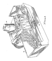
- FIG. 1 there is shown a simplified perspective view of an x-ray spot filming apparatus with which the present invention is particularly useful.
- the apparatus includes an x-ray table 10 and a spot filming apparatus 12.
- the spot filming apparatus 12 is supported above the table 10 on a column 14.
- the apparatus 12 can be moved vertically to raise or lower a film with respect to the upper surface of the table 10.
- the table 10 is supported by a pedestal 16.
- the table 10 may be moved by either rotation or longitudinally with respect to the spot film apparatus 12.
- the top of the table 10 constitutes a planar patient examining surface.
- the spot filming apparatus 12 and the support tower 14 are also capable of movement transversely with respect to the table top 10 by means of a support carriage (not shown).
- a conventional x-ray tube or source (not shown) is located within the table support 16.
- the spot filming apparatus 12 is attached to the tower 14 by a support frame that includes a pair of transversely extending arms 18, only one of which is visible in the illustrative FIG. 1.
- the arms 18 move vertically on the tower 14 for positioning the spot filming apparatus 12 vertically with respect to a patient located on the table 10.
- the spot filming apparatus 12 also slides within the support arms 18 on side support rails 20.
- the spot filming apparatus 12 is manually moved between a rearward position (as viewed in FIG. 1) and a forward position (the position shown in FIG. 1). In the rear position, the film is out of the direct line of the x-ray source within the support means 16 and is located in what is referred to as a non-operating poistion.
- the spot filming apparatus 12 In the forward or operating position, the spot filming apparatus 12 overhangs the patient examining surface on top of table 10.
- the normal operating mode of the system is to load a film cassette into a film holder in the spot filming apparatus 12 while the apparatus 12 is in the forward or operative position.
- the film holder 26 When a command is given to expose an image using the x-ray source in the support apparatus 16, the film holder 26 is driven so as to position a film in the proper location for exposure.
- Additional apparatus within the spot filming apparatus 12 may also be used to block portions of the film when it is desired to make multiple images on a single large sheet of film.
- FIG. 2 there is shown a top view of the spot filming apparatus 12 with all covers removed for illustrating the film holding mechanism and the drive mechanism for actual movement of the film holding mechanism.
- the apparatus 12 comprises an outer frame 22 with the attached side rails 20. Within the frame 22 are additional internal rails 24 on which an x-ray film holder 26 rides. Holder 26 also includes transversely moveable, with respect to the longer dimension of apparatus 12, side elements 28. The side elements are adjustable for holding different widths of film in the film holder and can be moved in synchronism for positioning a film in various positions.
- the film holder 26 is shown in an intermediate position between front stops 32 and rear stop 33. In the forward position, a cross-bar 30 will contact end stops 32.
- the film holder 26 is positioned by means of a motor drive mechanism including a motor 34 having a belt drive (not shown) for effecting rotation of geared pulleys 36.
- the pulleys 36 drive a belt 38 which is connected at each end to the film holder 26.
- the belt 38 passes around pulleys 40 and 44 at each end of the frame 22 of the spot film apparatus 12.
- the pulleys 40 are idler pulleys around which the belt 38 passes since the belt itself is driven by the pulley assembly 36 connected to the motor 34.
- the belt 38 is connected to each side of the film holder 26 so that the film holder 26 can be driven in either a forward or reverse direction by controlling the direction of drive of the motor 34.
- the outer arms 28 which are used to close on a film cassette holder (not shown) are driven by a second motor 44 also connected through a plurality of pulleys to a continuous drive cable 48 which is connected to each of the arms 28.
- the cable 48 also passes over idler pulleys 50, 52, 54, 56 located at each corner of the frame 22.
- idler pulleys 58 and 60 at each side of the film holder 26 which allow the cable to be turned at 90° to be connected to the arms 28.
- Additional pulleys 64 and 66 connected to the arms 28 and fastening means 68 provide a connection from the cable to the arms 28.
- the arms 28 can be made to open or close as needed.
- the film holder 26 including the arms 28 can be driven to different positions without the arms 28 opening or closing since the cable 48 will ride on the various pulleys as long as it is maintained at a constant length.
- a position sensor 70 Located at the forward end of the frame 22 is a position sensor 70.
- the position sensor 70 is geared to the pulley 42 such that an output signal is provided from the sensor 70 indicative of the actual position of the film holder 26.
- the position sensor 70 may comprise a potentiometer.
- the potentiometer may have its ends connected to a fixed voltage source so as to provide a variable voltage output signal as the position of the film holder 26 varies or it may simply provide a variable resistance proportional to the position of the film holder 26.
- Another potentiometer (not shown) is operatively connected to one of the pulleys about which cable 48 passes in order to provide a similar signal representative of the position of arms 28.
- the spot film apparatus thus far described is not considered to be a novel apparatus with respect to the present invention. More particularly, the spot film apparatus described above is part of a type 88 spot film device available from General Electric Company.
- the objective of the spot film device is to deliver a film cassette into an x-ray beam to record an x-ray image on the film within the film cassette. It is desirable, as previously stated, to perform this function as rapidly as possible.
- the control of the film holder 26 has involved applying a voltage to the motor 34 in which the voltage applied to the motor 34 has an amplitude proportional to the distance that the film holder 26 has to move. Velocity proportional fedback or lead network compensation is generally used for stability.
- the position command is an operator command input to a position processor 72 or control system for the motors within the spot film device.
- the position processor 72 includes a microprocessor for receiving the position command and for converting it to appropriate drive signals for a servo control amplifier within the position processor.
- the output signal developed by the position processor 72 in reality, a drive signal developed by the servo control within the position processor 72, is indicated as a position output command (POS OUTPUT) which is supplied to a comparator 74.
- a second input terminal of the comparator 74 is connected to receive a signal from the actual position sensor 70.
- the result of the comparison in comparator 74 is a speed command to motor 34.
- the position command signal is passed through the position processor 72 as a large delta command, i.e., a command related only to the difference in present position versus a desired position
- the error signal will initially represent a very large voltage to be applied to the motor 34. This will result in a rapid acceleration of the motor 34 causing the apparatus 26 to be rapidly accelerated towards a new positon.
- rapid acceleration results in structural vibrations in the cantilevered spot filming apparatus 12 which must settle out before an image can be exposed.
- Applicants have discovered that a solution to this problem is to provide continuous control of the positon, velocity, acceleration or other motion related attribute of the film holder 26 over its normal range of motion.
- the preferred method of controlling the film holder 26 is to cause the motion of the film holder 26 to describe a value as a function of time which tends to minimize the vibration of the supporting structure.
- the nature of the selected motion profile must be such that it generate a smooth motion of the film holder 26 but may take the form of a sine, gaussian, sine squared or similar smooth position versus time attribute.
- the main concern is that the motion control of the film holder 26 must exist throughout the entire transition. By controlling the motion over its entire transition distance, the force required to move the holder 26 is applied more gradually and constantly so that very little jerking of the holder 26 occurs.
- a preferred embodiment employs a sine curve in the form of an inverted cosine curve.
- FIG. 5 there is illustrated a graph of position versus time for a desired move between an original position and a new position.
- the implementation of the preferred method of control of the film holder 26 utilizes a microprocessor, as shown in FIG. 3, which generates a voltage versus time signal as a series of discrete voltages which represent the desired position versus time relationship.
- the amplitude of the position versus time relationship is determined by the length of the desired move and the shape of the move profile that is chosen to generate the smooth motion.
- the motion profile implemented is that shown in FIG. 5.
- the profile could be determined by solving the above equation for each increment of motion or at each clock cycle of the microprocessor, it has been found more feasible to implement the motion profile as a unit value function which can be stored in a look-up table in a manner well known in the art.
- the motion profile is broken down into a predetermined number of clock cycles, e.g., 500. The number of clock cycles chosen will vary with the type of system in which the invention is implemented.
- the unit move is divided into a predetermined number of clock times so that the time required to complete a move will be constant irrespective of the length of the move.
- the value associated with the cosine function i.e., the value of the cosine at any particular instant in time
- the only variable in such an implementation then becomes the amplitude of the move, i.e., the distance through which the film holder 26 is to move.
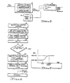
- FIG. 4 a flow chart for implementing the inventive method in a microprocessor or other computer in a position processor.
- the processor When the new position command is received by the position processor 72, the processor first sets the delta position equal to the new commanded position minus the current position of the film holder 26. Delta position then becomes the amplitude of the move, i.e., "A" as shown in the equation of motion described above. The original position of the film holder 26 is then equated to the current position so that each subsequent calculation will result in a different delta position. More particularly, the delta position or move amplitude will vary as the film holder 26 moves from its position at which the position command was first received to the desired position.
- block 82 is indicative of setting the pointer to the beginning of the look-up table, i.e., setting "I” equal to 0 where "I” equals the particular pointer position and actually forms a loop in a manner well known in the art.
- the block 84 is a "do while” block which causes the program to continue to run each sequential operation so long as the pointer position is less than the end point, i.e., "I" less than end point.
- the end point has been set at a value of "I" equal to 500, that is, a time of 500 clock cycles in order to process the entire unit value profile.
- I the program will step into the computational mode in which a value of the amplitude of the inverted cosine function can be computed at each time increment.
- Block 86 is indicative of computing the fraction representing the value of the cosine function as shown in FIG. 5 for each increment of time.
- the position output signal can be computed as the sum of the original position plus the fractional change times delta position, wherein the delta position represents the remaining distance to move between the current position and the new or desired position. This computed value is then outputted as a position output to the comparator 74.
- the final step in the program is to increment the value of "I" so that the program can then step to the next computed fractional value on the cosine function.
- the delta position will continue to be changed as the motor drives the film holder 26 to each new position.
- the position sensor 70 will provide a continuous output representative of the actual position of the film holder 26 which position output will then be compared to each new position output command from the position processor 72.
- the profile motion of the film holder 26 will thus follow the position versus time graph shown in FIG. 5.
- Such masks are motor driven in the same manner as the cassette holder and the present invention may be employed to reduce vibration induced by mask motion. Still further, such commercial apparatus also incorporate a palpitator cone which is power driven and may also induce vibrations which can be minimized by use of the present invention.
Landscapes
- Physics & Mathematics (AREA)
- General Physics & Mathematics (AREA)
- Radiography Using Non-Light Waves (AREA)
- Apparatus For Radiation Diagnosis (AREA)
Applications Claiming Priority (1)
| Application Number | Priority Date | Filing Date | Title |
|---|---|---|---|
| US06/792,276 US4651337A (en) | 1985-10-28 | 1985-10-28 | Film positioner |
Publications (2)
| Publication Number | Publication Date |
|---|---|
| EP0220632A2 true EP0220632A2 (de) | 1987-05-06 |
| EP0220632A3 EP0220632A3 (de) | 1987-12-23 |
Family
ID=25156336
Family Applications (1)
| Application Number | Title | Priority Date | Filing Date |
|---|---|---|---|
| EP86114435A Withdrawn EP0220632A3 (de) | 1985-10-28 | 1986-10-17 | Filmeinstellvorrichtung |
Country Status (2)
| Country | Link |
|---|---|
| US (1) | US4651337A (de) |
| EP (1) | EP0220632A3 (de) |
Families Citing this family (6)
| Publication number | Priority date | Publication date | Assignee | Title |
|---|---|---|---|---|
| US4845733A (en) * | 1987-05-01 | 1989-07-04 | Liebel-Flarsheim Company | Cassette film transport |
| US4872190A (en) * | 1988-02-23 | 1989-10-03 | Picker International, Inc. | Spot filmer cassette transport vibration support |
| US4957691A (en) * | 1989-05-30 | 1990-09-18 | Westinghouse Electric Corp. | Apparatus for inspecting the quality of nuclear fuel rod ends |
| US4994232A (en) * | 1989-05-30 | 1991-02-19 | Westinghouse Electric Corp. | Method of inspecting the quality of nuclear fuel rod ends |
| US5062130A (en) * | 1990-11-26 | 1991-10-29 | Liebel-Flarsheim Company | X-ray film cassette transport |
| US6898269B2 (en) * | 2003-02-10 | 2005-05-24 | Ge Medical Systems Global Technology Company, Llc | Methods and apparatus for x-ray images |
Family Cites Families (4)
| Publication number | Priority date | Publication date | Assignee | Title |
|---|---|---|---|---|
| US3862426A (en) * | 1973-11-21 | 1975-01-21 | Cgr Medical Corp | Electronically controlled spot film device |
| US4105920A (en) * | 1976-11-10 | 1978-08-08 | General Electric Company | X-ray spot film device |
| DE3035448C2 (de) * | 1980-09-19 | 1985-04-18 | Siemens AG, 1000 Berlin und 8000 München | Röntgenaufnahmeeinrichtung mit einem von einer Bereitschaftsstellung in eine Aufnehmestellung verfahrbaren Filmträger |
| DE3138911A1 (de) * | 1981-09-30 | 1983-04-14 | Siemens AG, 1000 Berlin und 8000 München | Roentgenuntersuchungsgeraet |
-
1985
- 1985-10-28 US US06/792,276 patent/US4651337A/en not_active Expired - Lifetime
-
1986
- 1986-10-17 EP EP86114435A patent/EP0220632A3/de not_active Withdrawn
Also Published As
| Publication number | Publication date |
|---|---|
| US4651337A (en) | 1987-03-17 |
| EP0220632A3 (de) | 1987-12-23 |
Similar Documents
| Publication | Publication Date | Title |
|---|---|---|
| EP0439711B1 (de) | Bilderfassungssystem mit kontinuierlicher Mehrfach-Abtastung für periphere Angiographie | |
| US4443742A (en) | Phase locked loop motor control system | |
| EP1159746A1 (de) | Antistreuungsvorrichtung mit einzelhub-strahlung für variabeles röntgenstrahlungsbllichtungsfenster | |
| EP0993239B1 (de) | Röntgeneinrichtung | |
| US4651337A (en) | Film positioner | |
| US4985907A (en) | Dental X-ray apparatus for panoramic tomography | |
| FR2371183A1 (fr) | Procede et appareil de tomographie | |
| US3976887A (en) | X-ray examination apparatus | |
| US5235627A (en) | X-ray diagnostic system | |
| EP1157661B1 (de) | Positionssteuerungssystem und -verfahren für ein Röntgengerät | |
| US4213050A (en) | Servo control for X-ray tomography | |
| JP3041543B2 (ja) | カメラ用シャッタの制御装置および制御方法 | |
| US3999044A (en) | Installation for producing radiological angiographic exposures | |
| US4449225A (en) | Method to be used in panoramic X-ray photography and an apparatus for carrying out the method | |
| DE2931274C2 (de) | Schaltungsanordnung zur Fokussierungsermittlung bei einer Kamera | |
| JP3055839B2 (ja) | 歯科用パノラマ断層撮影装置 | |
| McDavid et al. | Blurring effects in rotational panoramic radiography | |
| US5432833A (en) | Automatic exposure control system for tomographic applications | |
| EP0261407B1 (de) | Verfahren und Vorrichtung zum automatischen Scharfstellen in einem fotografischen Vergrösserungs- oder Kopiergerät mit veränderlichem Vergrösserungsmassstab | |
| EP0744156B1 (de) | Digitales angiographisches Gerät | |
| JPH0327616Y2 (de) | ||
| US4665540A (en) | Apparatus for making sectional radiographs | |
| JPH1033517A (ja) | 診断用x線装置 | |
| JPH0415440B2 (de) | ||
| JP2845595B2 (ja) | 描画装置用移動ステージ |
Legal Events
| Date | Code | Title | Description |
|---|---|---|---|
| PUAI | Public reference made under article 153(3) epc to a published international application that has entered the european phase |
Free format text: ORIGINAL CODE: 0009012 |
|
| AK | Designated contracting states |
Kind code of ref document: A2 Designated state(s): DE FR GB IT NL |
|
| PUAL | Search report despatched |
Free format text: ORIGINAL CODE: 0009013 |
|
| AK | Designated contracting states |
Kind code of ref document: A3 Designated state(s): DE FR GB IT NL |
|
| STAA | Information on the status of an ep patent application or granted ep patent |
Free format text: STATUS: THE APPLICATION IS DEEMED TO BE WITHDRAWN |
|
| 18D | Application deemed to be withdrawn |
Effective date: 19880624 |
|
| RIN1 | Information on inventor provided before grant (corrected) |
Inventor name: FRANK, STEVEN ROBINSON Inventor name: BOOMGAARDEN, JONATHAN CARL Inventor name: BAUTISTA, BRUCE QUIN Inventor name: DAVIS, CHARLES ROBERT |