EP0220615A2 - Adjustable table - Google Patents
Adjustable table Download PDFInfo
- Publication number
- EP0220615A2 EP0220615A2 EP86114304A EP86114304A EP0220615A2 EP 0220615 A2 EP0220615 A2 EP 0220615A2 EP 86114304 A EP86114304 A EP 86114304A EP 86114304 A EP86114304 A EP 86114304A EP 0220615 A2 EP0220615 A2 EP 0220615A2
- Authority
- EP
- European Patent Office
- Prior art keywords
- elements
- table according
- plate elements
- guide channels
- connecting rods
- Prior art date
- Legal status (The legal status is an assumption and is not a legal conclusion. Google has not performed a legal analysis and makes no representation as to the accuracy of the status listed.)
- Granted
Links
Images


Classifications
-
- A—HUMAN NECESSITIES
- A47—FURNITURE; DOMESTIC ARTICLES OR APPLIANCES; COFFEE MILLS; SPICE MILLS; SUCTION CLEANERS IN GENERAL
- A47B—TABLES; DESKS; OFFICE FURNITURE; CABINETS; DRAWERS; GENERAL DETAILS OF FURNITURE
- A47B87/00—Sectional furniture, i.e. combinations of complete furniture units, e.g. assemblies of furniture units of the same kind such as linkable cabinets, tables, racks or shelf units
- A47B87/002—Combination of tables; Linking or assembling means therefor
-
- A—HUMAN NECESSITIES
- A47—FURNITURE; DOMESTIC ARTICLES OR APPLIANCES; COFFEE MILLS; SPICE MILLS; SUCTION CLEANERS IN GENERAL
- A47B—TABLES; DESKS; OFFICE FURNITURE; CABINETS; DRAWERS; GENERAL DETAILS OF FURNITURE
- A47B1/00—Extensible tables
- A47B1/08—Extensible tables with extensible frames or with additional legs
-
- A—HUMAN NECESSITIES
- A47—FURNITURE; DOMESTIC ARTICLES OR APPLIANCES; COFFEE MILLS; SPICE MILLS; SUCTION CLEANERS IN GENERAL
- A47B—TABLES; DESKS; OFFICE FURNITURE; CABINETS; DRAWERS; GENERAL DETAILS OF FURNITURE
- A47B91/00—Feet for furniture in general
- A47B91/02—Adjustable feet
- A47B91/022—Adjustable feet using screw means
Definitions
- the invention relates to a variable table with a table top consisting of composite table elements, with table legs arranged on the undersides of the table elements and with connecting members for the table top plate elements.
- the object is achieved in that rectilinear guide channels are provided on the underside of the plate elements, that the connecting links separately as straight, in the guide channels insertable and longitudinally displaceable connecting rods are formed, and that the plate elements have locking members for locking the connecting rods in the guide channels and stabilizing the table.
- variable table 1 shown in Fig. 1 consists of two semicircular plate elements 2 and 3, which are joined together along a circle diameter with the help of connecting links to be described.
- Table legs 4, 5, 6, 7 are arranged on the plate elements 2, 3.
- the guide channels 9, 11 are formed on most of their longitudinal extent as a completely closed tunnel and have a rectangular inner cross-sectional profile.
- the connecting rods 13, 14 are designed as metal tubes and have a rectangular outer cross-sectional profile, which corresponds to the inner cross-sectional profile of the guide channels, so that the connecting rods are longitudinally displaceable in the guide channels.
- the guide rods 13, 14 are designed as separate parts which can be inserted into the guide channels 9, 11 and can be removed from them.
- the connecting rods 13, 14, which are inherently displaceable in the guide channels 9, 11, can be locked in certain positions by locking members.
- This lock also serves to stabilize the table composed of several plate elements.
- a clamping claw 15 is provided, which is fastened with a screw 16 to the plate element 2 and with its free end 17 presses against a flat side of the connecting rod 13, so that it is prevented from moving. After loosening the screws 16, the connecting rod 13 can be moved, brought into a new position and in turn can be fixed there by the claw 15.
- a toggle 19 is pivotally mounted on a pin 18 provided on the plate element 2, which in a conventional manner has a pressing surface 21 which is arranged eccentrically to the pin 18 and with which it can be pressed against a flank of the connecting rod 14 .
- the connecting rod 14 can thus be fixed in the guide channel 11 by correspondingly pivoting the toggle 19. After loosening the toggle 19, the rod 14 can be moved, brought into a new position and locked there again by pivoting the toggle 19. (See also Fig. 10).
- each plate element 2 On the straight side 12 of each plate element 2, 3 projecting pins 22, 23 are formed, which fit into corresponding recesses 24 and 25 of an adjacent plate element (see also Fig. 4).
- the table legs 4 to 7 are first screwed to the respective plate elements 2, 3. Subsequently, two connecting rods 13, 14 are inserted into the guide channels 9, 11 of one plate element 2 and locked there by means of the locking members 15 or 19 that they protrude a bit beyond the straight side 12, at least to the extent that they are separated from the Locking elements 15 or 19 of an adjacent plate element can be detected. Now the two plate elements 2, 3 by inserting the protruding pieces of the connecting rods 13, 14 in the guide channels in question are joined and firmly connected to one another by actuating the locking members, so that the circular table shown in FIG. 1 results.
- the circular table according to FIG. 1 can be transformed into an approximately oval table according to FIG. 2 by inserting a rectangular plate element 26 between the plate elements 2 and 3.
- 5 shows the underside of the rectangular plate element 26, on which in turn guide channels 27, 28 are provided for receiving the connecting rods 13, 14.
- the guide channels 27, 28 are not closed in the manner of a tunnel all around, but rather are designed as channels which are open downwards over their entire longitudinal extent.
- the rectangular plate element 26 can be easily inserted and removed between two correspondingly widely spread plate elements 2, 3 connected by the connecting rods 13, 14.
- locking elements in the form of the claws 15 can also be provided on the underside of the plate element 26 (FIG. 5), which fix the plate element 26 relative to the rods 13, 14 lock, which in turn are determined by the locking elements 15 or 19 provided on the plate elements 2, 3.
- the connecting rods 13, 14 advantageously have a length such that they from the 1 completely fill the guide channels 9, 11 on both plate elements 2, 3 and - as shown in Fig. 3 - extend approximately to the circular edge of these elements.
- the connecting rods 9, 11 are long enough to be able to pull apart the two plate elements 2, 3 as shown in FIG. 2 for the purpose of inserting the rectangular plate element 26, but both connecting rods 9, 11 by the locking elements 19 on both plate elements 2 , 3 can still be locked.
- the tunnel-like closed guide channels 9, 11 have longitudinal slots 29 on their undersides.
- resilient locking elements 31 are provided, the construction of which can be seen in FIG. 9.
- the internally hollow connecting rods 13 have holes 32 near their ends, in which cylindrical locking pins 33 are inserted.
- the locking pins 33 are firmly connected on their rear side to one leg 34 of a V-shaped spring 35, the other leg 36 of which is supported on the inner wall of the connecting rod 13 opposite the bore 32.
- the locking pin 33 is resiliently held within the bore 32 and can be pressed so far into the interior of the rod 13 that its top is flush with the outside of the connecting rod 13.
- the connecting rod 13 When the locking pin 33 is pressed in, the connecting rod 13 can be inserted into the associated Guide channel 9 are inserted. After a correspondingly long insertion, the locking pin 33 snaps out again in the area of the longitudinal slot 29, so that the connecting rod 13 is now displaceable in the area of the longitudinal slot 29, but is prevented from being pulled out of its guide channel as long as the locking pin 33 is not pressed in again.
- the two locking pins 31 of the guide rods 9, 11 assume the position shown in FIG. 3 at one end of the longitudinal slots 29.
- the two locking pins 31 abut the opposite (lower in FIG. 3) ends of the longitudinal slots 29.
- connection rods 13, 14 are normally not sufficient. These rods must therefore be extended by attaching extension elements, as shown in Fig. 11.
- An extension element 37 in the form of a metal tube with a rectangular cross section has at its one end a likewise tubular projection 38 of rectangular cross section. The size of the cross section of the projection 38 on the extension element 37 is selected so that the projection 38 fits snugly into the connecting rod 13 to be extended.
- a resilient locking pin 33 is provided in the projection 38, which corresponds in structure and mode of operation to the locking pin 33 according to FIG. 9.
- the verb Extension rod 13 has at its front end a bore 39 (FIGS. 9 and 11) into which the locking pin 33 snaps into the connecting rod 13 when telescoping the projection 38. In this way, the connecting rod 13 can be extended by the extension element 37.
- the extension element 37 is designed at its end opposite the locking pin 33 (not shown in FIG. 11) as well as the connecting rod 13 according to FIG. 11, so that it can be extended by a further extension element 37.
- a total of connecting rods of any length can be produced, which in turn enable the design of tables in a wide variety of variations.
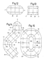
- FIG. 13 schematically shows a table with an essentially rectangular cross section, which is composed of two rectangular plate elements 26 and two narrower, rectangular end pieces 41 using corresponding connecting rods, indicated by dashed lines in FIG. 13.
- 6 shows a bottom view of the connection of an edge piece 41 to a plate element 26.
- pins 22, 23 are again provided, which engage in corresponding recesses 24 and 25, respectively.
- tunnel-like closed guide channels 42, 43 are provided, into which the ends of connecting rods 13, 14 can be inserted. Gags 19 allow the connecting rods 13, 14 to be locked in the guide channels 42, 43.
- screw bushings 8 are provided for fastening table legs 4, 5.
- the arrangement of these screw bushings is such that two bushings are provided on the plate element 26 and on the edge piece 41, respectively.
- the screwed table leg bridges the butt joint between plate element 26 and edge piece 41 and contributes to the firm connection of these parts. Even with two abutting plate elements 26, a screwed table leg would bridge the two elements.
- leveling screws 44 are provided, via which the table leg rests on the floor. These leveling screws allow the effective table leg length to be changed so that the table can be set up with a horizontal table top without wobbling. 7 and 8, the design and operation of a leveling screw 44 is shown.
- the leveling screw 44 comprises a threaded shaft 45 and a screw head 46.
- the shaft 45 is screwed into a nut 47 provided with a corresponding internal thread, which in turn is firmly connected to the lower end of the table leg 6.
- a thread-free collar 48 provided at the free end of the shaft 45 prevents the leveling screw 44 from being unscrewed from the nut 47.
- the screw 44 is thus captively connected to the table leg.
- the nut 47 consists of two half-shells 49, 51 enclosing the shaft, which have locking lugs 52 at their ends facing the table leg 6.
- a chamber is provided at the lower end of the table leg 6, which has an opening 53 adapted to the catch 52 in its bottom.
- a slot 54 provided between the locking lugs at the end of the half-shells 49, 51 gives the locking lugs 52 a resilient character.
- the two half shells 49, 51 are injection molded from plastic.
- the two half-shells 49, 51 can be connected to one another by a so-called plastic film hinge.
- the two half shells 49, 51 of the nut 47 are first placed around the shaft 45 of the screw 44.
- the half-shells with the enclosed threaded shaft are then introduced into the chamber mentioned in such a way that the latching noses penetrate the opening 53 in the bottom of the chamber and then snap behind the bottom. This fixes the whole arrangement on the table leg.
- An inner ring web 55 in the nut 47 interacts with the collar on the shaft 48 of the screw 44 and prevents the screw 44 from being completely unscrewed from the nut 47.
- the semicircular plate elements 2 the rectangular plate elements 26 and the edge pieces 41 are also sector-shaped plate elements 56.
- These sector-shaped elements 56 are each delimited by two straight sides 12 enclosing an angle of 45 ° and by two arcs 57, 58 of different radii.
- the length of the straight sides 12 corresponds to the length of the straight sides 12 of the semicircular plate element 2 and the longer side of the plate elements 26.
- FIG. 14 shows a multi-curved table, with two arms 59, 61 running at right angles to one another and a further, straight arm 62 which encloses an angle of 135 ° with arm 61. Between the arms 59, 61 two, between the arms 61 and 62 a sector-shaped plate element 56 are arranged.
- 15 shows a large oval table, the rounded sides of which are each formed by four sector-shaped plate elements 56. 15 has a central recess 63.
- the undersides of the sector-shaped plate elements 56 like the undersides of the semicircular and rectangular plate elements 2, 26 according to FIGS. 3 and 6, are formed, that is to say they are essentially provided with guide channels for connecting rods, the connecting rods in turn being held in the guide by locking members channels can be locked.
- the course of the guide channels and the connecting rods is indicated by dashed lines in FIGS. 14 and 15.
- the guide channels on the sector-shaped plate elements 56 each run perpendicular to the straight sides 12. They can also cut within a plate element 56 - as indicated in area D in FIG. 14 - in order to accommodate longer connecting rods in this way.
Abstract
Description
Die Erfindung betrifft einen variablen Tisch mit einer aus zusammensetzbaren Plattenelementen bestehenden Tischplatte, mit an den Unterseiten der Plattenelemente angeordneten Tischbeinen und mit Verbindungsgliedern für die Plattenelemente der Tischplatte.The invention relates to a variable table with a table top consisting of composite table elements, with table legs arranged on the undersides of the table elements and with connecting members for the table top plate elements.
Bei den bekannten Tischen dieser Art ist die Anzahl der Verwandlungsmöglichkeiten begrenzt, was in erster Linie auf die Ausbildung und Befestigung der an den Plattenelementen vorgesehenen Verbindungsglieder zurückzuführen ist.In the known tables of this type, the number of possible transformations is limited, which is primarily due to the design and attachment of the connecting elements provided on the plate elements.
Es ist Aufgabe der Erfindung, die Variabilität eines gattungsgemäßen Tisches mit einfachen Mitteln zu verbessern.It is an object of the invention to improve the variability of a generic table with simple means.
Die Aufgabe wird erfindungsgemäß dadurch gelöst, daß an der Unterseite der Plattenelemente geradlinige Führungskanäle vorgesehen sind, daß die Verbindungsglieder separat als gerade, in die Führungskanäle einsetzbare und darin längsweise verschiebliche Verbindungsstangen ausgebildet sind, und daß die Plattenelemente Feststellorgane aufweisen zum Arretieren der Verbindungsstangen in den Führungskanälen und Stabilisieren des Tisches.The object is achieved in that rectilinear guide channels are provided on the underside of the plate elements, that the connecting links separately as straight, in the guide channels insertable and longitudinally displaceable connecting rods are formed, and that the plate elements have locking members for locking the connecting rods in the guide channels and stabilizing the table.
Die nachstehende Beschreibung bevorzugter Ausführungsformen eines variablen Tisches dient im Zusammenhang mit beiliegender Zeichnung der weiteren Erläuterung der Erfindung: Es zeigen:
- Fig. 1 einen variablen Tisch in runder Ausführungsform;
- Fig. 2 eine erste Abwandlung des Tisches aus Fig. 1;
- Fig. 3 eine Untenansicht eines Plattenelementes in Richtung des Pfeiles A in Fig. 1;
- Fig. 4 eine Schnittansicht entlang der Linie 4-4 in Fig. 3;
- Fig. 4b eine Teilschnittansicht entsprechend dem Kreis B in Fig. 4;
- Fig. 4c eine Teilschnittansicht entsprechend dem Kreis C in Fig. 4;
- Fig. 5 eine Untenansicht eines rechteckigen, für den Tisch gemäß Fig. 2 verwendeten Plattenelements;
- Fig. 6 eine Schnittansicht entlang der Linie 6-6 in Fig. 5;
- Fig. 7 eine Teilschnittansicht mit der Darstellung einer Nivellierschraube entlang der Linie 7-7 in Fig. 1;
- Fig. 8 eine Schnittansicht entlang der Linie 8-8 in Fig. 7;
- Fig. 9, 10 und 11 teilweise geschnittene Ansichten rohrförmiger Verbindungsstangen und
- Fig. 12 bis 15 verschiedene Variationsmöglichkeiten des Tisches gemäß Fig. 1 und 2.
- Figure 1 shows a variable table in a round embodiment.
- FIG. 2 shows a first modification of the table from FIG. 1;
- 3 shows a bottom view of a plate element in the direction of arrow A in FIG. 1;
- Fig. 4 is a sectional view taken along line 4-4 in Fig. 3;
- Fig. 4b is a partial sectional view corresponding to the circle B in Fig. 4;
- Fig. 4c is a partial sectional view corresponding to the circle C in Fig. 4;
- Fig. 5 is a bottom view of a rectangular plate member used for the table of Fig. 2;
- Fig. 6 is a sectional view taken along line 6-6 in Fig. 5;
- Fig. 7 is a partial sectional view showing a leveling screw along the line 7-7 in Fig. 1;
- Fig. 8 is a sectional view taken along line 8-8 in Fig. 7;
- 9, 10 and 11 are partially sectional views of tubular connecting rods and
- 12 to 15 different possible variations of the table according to FIGS. 1 and 2.
Der in Fig. 1 dargestellte variable Tisch 1 besteht aus zwei halbkreisförmigen Plattenelementen 2 und 3, die entlang einem Kreisdurchmesser mit Hilfe noch zu beschreibender Verbindungsglieder aneinandergefügt sind. An den Plattenelementen 2, 3 sind Tischbeine 4, 5, 6, 7 angeordnet.The variable table 1 shown in Fig. 1 consists of two
Die Fig. 3 zeigt eine Untenansicht des Plattenelements 2, welches mit dem Plattenelement 3 übereinstimmt. Die Plattenelemente 2, 3, die ebenso wie die Tischbeine 4 bis 7 in der Regel aus Kunststoff gespritzt sind, jedoch auch aus anderen Materialien, beispielsweise aus Holz bestehen können, weisen an ihrer Unterseite Schraubbuchsen 8 zur Befestigung der Tischbeine 4 bis 7 auf. Ferner sind an der Unterseite der Plattenelemente Führungskanäle 9, 11 ausgebildet, z.B. angespritzt, welche senkrecht zu der geradlinigen Seite 12 des Plattenelements verlaufen und der Aufnahme von starren Verbindungsstangen 13 bzw. 14 dienen. Die Führungskanäle 9, 11 sind auf dem größten Teil ihrer Längserstreckung als ringsum geschlossene Tunnels ausgebildet und weisen ein rechteckiges Innenquerschnittsprofil auf. Die Verbindungsstangen 13, 14 sind als Metallrohre ausgebildet und haben ein rechteckiges Außenquerschnittsprofil, welches dem Innenquerschnittsprofil der Führungskanäle entspricht, so daß die Verbindungsstangen in den Führungskanälen längsverschieblich sind. Die Führungsstangen 13, 14 sind als separate Teile ausgebildet, die in die Führungskanäle 9, 11 einsetzbar sind und aus diesen wieder herausgenommen werden können.3 shows a bottom view of the
Wie insbesondere aus Fig. 4, 4b und 4c hervorgeht, können die an sich in den Führungskanälen 9, 11 verschieblichen Verbindungsstangen 13, 14 in bestimmten Lagen durch Feststellorgane arretiert werden. Diese Arretierung dient gleichzeitig dem Stabilisieren des aus mehreren Plattenelementen zusammengesetzten Tisches. Bei der in Fig. 4b dargestellten Ausführungsform eines Feststellorganes ist eine Spannpratze 15 vorgesehen, die mit einer Schraube 16 am Plattenelement 2 befestigt ist und mit ihrem freien Ende 17 gegen eine Flachseite der Verbindungsstange 13 drückt, so daß diese an einer Verschiebung gehindert ist. Nach Lösen der Schrauben 16 kann die Verbindungsstange 13 verschoben, in eine neue Lage gebracht und dort wiederum durch die Pratze 15 festgestellt werden.As can be seen in particular from FIGS. 4, 4b and 4c, the connecting
Bei der in Fig. 4c dargestellten Ausführungsform eines Feststellorganes ist an einem am Plattenelement 2 vorgesehenen Bolzen 18 schwenkbar ein Knebel 19 gelagert, der in herkömmlicher Weise eine zum Bolzen 18 exentrisch angeordnete Anpreßfläche 21 aufweist, mit welcher er an eine Flanke der Verbindungsstange 14 anpreßbar ist. Durch entsprechende Verschwenkung des Knebels 19 kann somit die Verbindungsstange 14 im Führungskanal 11 festgestellt werden. Nach Lösen des Knebels 19 kann die Stange 14 verschoben, in eine neue Lage gebracht und dort wiederum durch Verschwenken des Knebels 19 arretiert werden. (Vgl. auch Fig. 10).In the embodiment of a locking element shown in FIG. 4c, a
An der geraden Seite 12 jedes Plattenelementes 2, 3 sind vorstehende Zapfen 22, 23 ausgebildet, die in entsprechende Ausnehmungen 24 bzw. 25 eines angrenzenden Plattenelementes passen (vergleiche auch Fig. 4).On the
Beim Aufbau des Tisches gemäß Fig. 1 werden zunächst die Tischbeine 4 bis 7 an die jeweiligen Plattenelemente 2, 3 angeschraubt. Anschließend werden zwei Verbindungsstangen 13, 14 so in die Führungskanäle 9, 11 des einen Plattenelements 2 eingesetzt und dort mittels der Feststellorgane 15 oder 19 arretiert, daß sie ein Stück über die gerade Seite 12 überstehen, und zwar mindestens so weit, daß sie von den Feststellorganen 15 oder 19 eines angrenzenden Plattenelements erfaßt werden können. Nunmehr werden die beiden Plattenelemente 2, 3 durch Einführen der vorstehenden Stücke der Verbindungsstangen 13, 14 in die betreffenden Führungskanäle zusammengefügt und durch Betätigung der Feststellorgane fest miteinander verbunden, so daß sich der in Fig. 1 dargestellte, kreisrunde Tisch ergibt.1, the
Der kreisrunde Tisch gemäß Fig. 1 kann durch Einsetzen eines rechteckigen Plattenelements 26 zwischen die Plattenelemente 2 und 3 in einen etwa ovalen Tisch gemäß Fig. 2 verwandelt werden. Fig. 5 zeigt die Unterseite des rechteckigen Plattenelements 26, an der wiederum Führungskanäle 27, 28 zur Aufnahme der Verbindungsstangen 13, 14 vorgesehen sind. Im Gegensatz zu den Führungskanälen 9, 11 an den Plattenelementen 2 (Fig. 3) sind die Führungskanäle 27, 28 nicht ringsum tunnelartig geschlossen, sondern über ihre gesamte Längserstreckung hinweg als nach unten offene Rinnen ausgebildet. Somit kann das rechteckige Plattenelement 26 ohne weiteres zwischen zwei entsprechend weit auseinandergezogene, durch die Verbindungsstangen 13, 14 verbundene Plattenelemente 2, 3 eingefügt und wieder herausgenommen werden. Zur Stabilisierung des aus den Plattenelementen 2, 3, 26 bestehenden Tisches gemäß Fig. 2 können auch an der Unterseite des Plattenelements 26 Feststellorgane in Form der Pratzen 15 vorgesehen werden (Fig. 5), welche das Plattenelement 26 relativ zu den Stangen 13, 14 arretieren, welche ihrerseits durch die an den Plattenelementen 2, 3 vorgesehenen Feststellorgane 15 oder 19 festgestellt sind.The circular table according to FIG. 1 can be transformed into an approximately oval table according to FIG. 2 by inserting a
Die Verbindungsstangen 13, 14 haben vorteilhafter Weise eine solche Länge, daß sie bei dem aus den Plattenelementen 2, 3 gemäß Fig. 1 hergestellten Tisch die Führungskanäle 9, 11 an beiden Plattenelementen 2, 3 vollständig ausfüllen und - wie in Fig. 3 dargestellt - etwa bis zum kreisrunden Rand dieser Elemente reichen. In diesem Falle sind die Verbindungsstangen 9, 11 ausreichend lang, um die beiden Plattenelemente 2, 3 entsprechend Fig. 2, zwecks Einlegen des rechteckigen Plattenelements 26, auseinanderziehen zu können, wobei jedoch beide Verbindungsstangen 9, 11 durch die Feststellorgane 19 an beiden Plattenelementen 2, 3 noch arretierbar sind.The connecting
Wie Fig. 3 zeigt, weisen die tunnelartig geschlossenen Führungskanäle 9, 11 an ihren Unterseiten Längsschlitze 29 auf. An den als Rechteckrohre ausgebildeten Verbindungsstangen 13, 14 sind federnde Rastelemente 31 vorgesehen, deren Konstruktion aus Fig. 9 ersichtlich ist. Die inwendig hohlen Verbindungsstangen 13 weisen in der Nähe ihrer Enden Bohrungen 32 auf, in welche zylindrische Rastzapfen 33 eingesetzt sind. Die Rastzapfen 33 sind an ihrer Rückseite mit dem einen Schenkel 34 einer V-förmig gebogenen Feder 35 fest verbunden, deren anderer Schenkel 36 sich an der der Bohrung 32 gegenüberliegenden Innenwand der Verbindungsstange 13 abstützt. Hierdurch ist der Rastzapfen 33 innerhalb der Bohrung 32 federnd gehalten und kann so weit in das Innere der Stange 13 eingedrückt werden, daß seine Oberseite mit der Außenseite der Verbindungsstange 13 bündig ist. Bei eingedrücktem Rastzapfen 33 kann die Verbindungsstange 13 in den zugehörigen Führungskanal 9 eingeschoben werden. Nach entsprechend weitem Einschieben schnappt der Rastzapfen 33 im Bereich des Längsschlitzes 29 wieder nach außen, so daß nunmehr die Verbindungsstange 13 im Bereich des Längsschlitzes 29 verschieblich, jedoch an einem Herausziehen aus ihrem Führungskanal gehindert ist, solange der Rastzapfen 33 nicht wieder eingedrückt wird.3 shows, the tunnel-like closed
Bei dem Tisch gemäß Fig. 1 nehmen die beiden Rastzapfen 31 der Führungsstangen 9, 11 die in Fig. 3 dargestellte Position am einen Ende der Längsschlitze 29 ein. Bei dem Tisch gemäß Fig. 2 schlagen die beiden Rastzapfen 31 an den gegenüberliegenden (in Fig. 3 unteren) Enden der Längsschlitze 29 an.In the table according to FIG. 1, the two locking
Wenn entsprechend der schematischen Darstellung gemäß Fig. 12 zwischen zwei halbkreisförmige Plattenelemente 2, 3 zwei rechteckige Plattenelemente 26 eingesetzt werden sollen, reicht die Länge der Verbindungsstangen 13, 14 normalerweise nicht aus. Diese Stangen müssen daher durch Ansetzen von Verlängerungselementen verlängert werden, wie dies in Fig. 11 dargestellt ist. Ein Verlängerungselement 37 in Gestalt eines Metallrohres mit Rechteckquerschnitt weist an seinem einen Ende einen ebenfalls rohrförmigen Vorsprung 38 rechteckigen Querschnitts auf. Die Größe des Querschnitts des Vorsprungs 38 am Verlängerungselement 37 ist so gewählt, daß der Vorsprung 38 paßgenau in die zu verlängernde Verbindungsstange 13 paßt. Im Vorsprung 38 ist ein federnder Rastzapfen 33 vorgesehen, der in Aufbau und Wirkungsweise dem Rastzapfen 33 gemäß Fig. 9 entspricht. Die Verbin dungsstange 13 weist an ihrem vorderen Ende eine Bohrung 39 (Fig. 9 und 11) auf, in welche der Rastzapfen 33 beim teleskopierenden Ineinanderschieben des Vorsprungs 38 in die Verbindungsstange 13 einrastet. Auf diese Weise kann die Verbindungsstange 13 durch das Verlängerungselement 37 verlängert werden.If two
Das Verlängerungselement 37 ist an seinem dem Rastzapfen 33 gegenüberliegenden (in Fig. 11 nicht mehr dargestellten) Ende ebenso wie die Verbindungsstange 13 gemäß Fig. 11 gestaltet, so daß es um ein weiteres Verlängerungselement 37 verlängert werden kann. Somit lassen sich insgesamt Verbindungsstangen beliebiger Länge herstellen, die wiederum die Ausbildung von Tischen in den verschiedensten Variationen ermöglichen.The
Die Fig. 13 zeigt schematisch einen Tisch mit im wesentlichen rechteckigem Querschnitt, der aus zwei rechteckigen Plattenelementen 26 und zwei schmäleren, rechteckigen Abschlußstücken 41 unter Verwendung entsprechender, in Fig. 13 gestrichelt angedeuteter Verbindungsstangen zusammengesetzt ist. Die Fig. 6 zeigt in Untenansicht die Verbindung eines Randstückes 41 mit einem Plattenelement 26. An den aneinanderstoßenden, geradlinigen Seiten 12 von Plattenelement 26 und Randstück 41 sind jeweils wiederum Zapfen 22, 23 vorgesehen, die in entsprechende Ausnehmungen 24 bzw. 25 eingreifen. Ferner sind an der Unterseite des Randstücks 41 tunnelartig geschlossene Führungskanäle 42, 43 vorgesehen, in welche die Enden von Verbindungsstangen 13, 14 eingesteckt werden können. Knebel 19 ermöglichen eine Arretierung der Verbindungsstangen 13, 14 in den Führungskanälen 42, 43.FIG. 13 schematically shows a table with an essentially rectangular cross section, which is composed of two
An den Unterseiten des Plattenelements 26 und des Randstücks 41 sind Schraubbuchsen 8 zur Befestigung von Tischbeinen 4, 5 vorgesehen. Die Anordnung dieser Schraubbuchsen ist so getroffen, daß jeweils zwei Buchsen am Plattenelement 26 bzw. am Randstück 41 vorgesehen sind. Hierdurch überbrückt das angeschraubte Tischbein die Stoßfuge zwischen Plattenelement 26 und Randstück 41 und trägt zur festen Verbindung dieser Teile bei. Auch bei zwei aneinanderstoßenden Plattenelementen 26 würde ein angeschraubtes Tischbein die beiden Elemente überbrücken.On the undersides of the
Am unteren Ende eines oder mehrerer Tischbeine (Fig. 1 und 2) sind Nivellierschrauben 44 vorgesehen, über welche das Tischbein am Bcden aufruht. Diese Nivellierschrauben gestatten ein Verändern der wirksamen Tischbeinlänge, so daß der Tisch, ohne zu wackeln mit waagrechter Tischplatte aufstellbar ist. In den Fig. 7 und 8 ist die Ausbildung und Wirkungsweise einer Nivellierschraube 44 dargestellt. Die Nivellierschraube 44 umfaßt einen Gewindeschaft 45 und einen Schraubkopf 46. Der Schaft 45 ist in eine mit entsprechendem Innengewinde versehene Mutter 47 eingedreht, die ihrerseits fest mit dem unteren Ende des Tischbeins 6 verbunden ist. Ein am freien Ende des Schaftes 45 vorgesehener, gewindefreier Bund 48 verhindert, daß die Nivellierschraube 44 aus der Mutter 47 herausgedreht werden kann. Die Schraube 44 ist somit unverlierbar mit dem Tischbein verbunden.At the lower end of one or more table legs (Fig. 1 and 2) leveling screws 44 are provided, via which the table leg rests on the floor. These leveling screws allow the effective table leg length to be changed so that the table can be set up with a horizontal table top without wobbling. 7 and 8, the design and operation of a leveling
Die Mutter 47 besteht aus zwei den Schaft umschliessenden Halbschalen 49, 51, die an ihren dem Tischbein 6 zugekehrten Enden Rastnasen 52 aufweisen. Zur Aufnahme der aus den beiden Halbschalen 49, 51 bestehenden Mutter 47 ist am unteren Ende des Tischbeins 6 eine Kammer vorgesehen, welche in ihrem Boden eine den Rastnasen 52 angepaßte Öffnung 53 aufweist. Ein zwischen den Rastnasen am Ende der Halbschalen 49, 51 jeweils vorgesehener Schlitz 54 verleiht den Rastnasen 52 federnden Charakter.The
Die beiden Halbschalen 49, 51 werden, ebenso wie die Nivellierschraube 44, aus Kunststoff gespritzt. Die beiden Halbschalen 49, 51 können durch ein sogenanntes Filmscharnier aus Kunststoff miteinander verbunden sein.The two
Beim Zusammenbauen werden zunächst die beiden Halbschalen 49, 51 der Mutter 47 um den Schaft 45 der Schraube 44 herumgelegt. Anschließend werden die Halbschalen mit dem umschlossenen Gewindeschaft in die erwähnte Kammer so eingeführt, daß die Rastnasen die Öffnung 53 im Boden der Kammer durchdringen und danach hinter dem Boden einschnappen. Hierdurch ist die ganze Anordnung am Tischbein fixiert. Ein innerer Ringsteg 55 in der Mutter 47 wirkt mit dem Bund am Schaft 48 der Schraube 44 zusammen und verhindert ein vollständiges Herausdrehen der Schraube 44 aus der Mutter 47.When assembling, the two
Die Fig. 14 und 15 zeigen weitere Variationsmöglichkeiten für den beschriebenen Tisch. Als weiterer Bestandteil sind bei diesen Tischabwandlungen neben den halbkreisförmigen Plattenelementen 2, den rechteckigen Plattenelementen 26 und den Randstücken 41 noch sektorförmige Plattenelemente 56 vorgesehen. Diese sektorförmigen Elemente 56 sind jeweils von zwei einen Winkel von 45° miteinander einschließenden, geraden Seiten 12 sowie von zwei Kreisbögen 57, 58 unterschiedlicher Radien begrenzt. Die Länge der geradlinigen Seiten 12 entspricht dabei der Länge der geradlinigen Seiten 12 des halbkreisförmigen Plattenelements 2 sowie der längeren Seite der Plattenelemente 26.14 and 15 show further possible variations for the table described. Another component of these table modifications are: the
In Fig. 14 ist ein mehrfach gekrümmter Tisch dargestellt, mit zwei rechtwinklig zueinander verlaufenden Armen 59, 61 und einem weiteren, geradlinigen Arm 62, der mit dem Arm 61 einen Winkel von 135° einschließt. Zwischen den Armen 59, 61 sind zwei, zwischen den Armen 61 und 62 ein sektorförmiges Plattenelement 56 angeordnet.FIG. 14 shows a multi-curved table, with two
Die Fig. 15 zeigt einen großen ovalen Tisch, dessen abgerundete Seiten jeweils von vier sektorförmigen Plattenelementen 56 gebildet werden. Der Tisch gemäß Fig. 15 weist eine zentrale Ausnehmung 63 auf.15 shows a large oval table, the rounded sides of which are each formed by four sector-shaped
Die Unterseiten der sektorförmigen Plattenelemente 56 sind ebenso wie die Unterseiten der halbkreisförmigen und rechteckigen Plattenelemente 2, 26 gemäß Fig. 3 bzw. 6 ausgebildet, d.h. sie sind im wesentlichen mit Führungskanälen für Verbindungsstangen versehen, wobei die Verbindungsstangen wiederum durch Feststellorgane in den Führungs kanälen arretierbar sind. Der Verlauf der Führungskanäle und der Verbindungsstangen ist in Fig. 14 und 15 gestrichelt angedeutet.The undersides of the sector-shaped
Die Führungskanäle an den Sektorförmigen Plattenelementen 56 verlaufen jeweils senkrecht zu den geradlinigen Seiten 12. Sie können sich auch innerhalb eines Plattenelements 56 - wie im Bereich D in Fig. 14 angedeutet - schneiden, um auf diese Weise längere Verbindungsstangen aufzunehmen.The guide channels on the sector-shaped
Claims (15)
dadurch gekennzeichnet, daß an der Unterseite der Plattenelemente (2, 3; 26; 41, 56) geradlinige Führungskanäle (9, 11; 27, 28; 42, 43) vorgesehen sind, daß die Verbindungsglieder separat als gerade, in die Führungskanäle einsetzbare und darin längsweise verschiebliche Verbindungsstangen (13, 14; 37) ausgebildet sind, und daß die Plattenelemente Feststellorgane (15, 19) aufweisen zum Arretieren der Verbindungsstangen in den Führungskanälen und Stabilisieren des Tisches (1).1. variable table with a table top consisting of assemblable plate elements, with table legs arranged on the undersides of the plate elements and with connecting members for the plate elements of the table top,
characterized in that rectilinear guide channels (9, 11; 27, 28; 42, 43) are provided on the underside of the plate elements (2, 3; 26; 41, 56) in that the connecting links can be inserted separately as straight, into the guide channels and longitudinally displaceable connecting rods (13, 14; 37) are formed therein, and the plate elements have locking elements (15, 19) for locking the connecting rods in the guide channels and stabilizing the table (1).
Priority Applications (1)
| Application Number | Priority Date | Filing Date | Title |
|---|---|---|---|
| AT86114304T ATE56127T1 (en) | 1985-10-25 | 1986-10-16 | VARIABLE TABLE. |
Applications Claiming Priority (2)
| Application Number | Priority Date | Filing Date | Title |
|---|---|---|---|
| DE3538003A DE3538003C2 (en) | 1985-10-25 | 1985-10-25 | Variable table |
| DE3538003 | 1985-10-25 |
Publications (3)
| Publication Number | Publication Date |
|---|---|
| EP0220615A2 true EP0220615A2 (en) | 1987-05-06 |
| EP0220615A3 EP0220615A3 (en) | 1988-02-03 |
| EP0220615B1 EP0220615B1 (en) | 1990-09-05 |
Family
ID=6284454
Family Applications (1)
| Application Number | Title | Priority Date | Filing Date |
|---|---|---|---|
| EP86114304A Expired - Lifetime EP0220615B1 (en) | 1985-10-25 | 1986-10-16 | Adjustable table |
Country Status (3)
| Country | Link |
|---|---|
| EP (1) | EP0220615B1 (en) |
| AT (1) | ATE56127T1 (en) |
| DE (2) | DE3538003C2 (en) |
Cited By (3)
| Publication number | Priority date | Publication date | Assignee | Title |
|---|---|---|---|---|
| EP0804988A1 (en) * | 1996-04-29 | 1997-11-05 | Selco Spa | Cutting machine and table extension |
| US6698363B2 (en) * | 2002-07-30 | 2004-03-02 | Outdoor Designs, Ltd. | Extendable table |
| EP1336354B1 (en) * | 2002-02-18 | 2008-04-02 | Garten- und Landschaftsbau, Manfred Siegwarth | Table comprising a divided table-top |
Families Citing this family (1)
| Publication number | Priority date | Publication date | Assignee | Title |
|---|---|---|---|---|
| CN107048691A (en) * | 2016-11-10 | 2017-08-18 | 浙江捷昌线性驱动科技股份有限公司 | A kind of length-adjustable table frame and desk |
Citations (6)
| Publication number | Priority date | Publication date | Assignee | Title |
|---|---|---|---|---|
| US2825613A (en) * | 1957-02-04 | 1958-03-04 | Henry J Gariepy | Table slides |
| US2955888A (en) * | 1958-10-16 | 1960-10-11 | Alfreda E Graves | Detachable extension table top |
| US3515077A (en) * | 1967-06-12 | 1970-06-02 | Matthew P Glowacki | Slide assembly for extendable tables |
| FR2070314A5 (en) * | 1969-12-01 | 1971-09-10 | Jouk Leon | |
| US3974782A (en) * | 1975-06-09 | 1976-08-17 | Winzeler Stamping Co. | Slide assembly for extendable table |
| EP0136657A2 (en) * | 1983-09-30 | 1985-04-10 | Ilan Samson | Extendable table |
Family Cites Families (1)
| Publication number | Priority date | Publication date | Assignee | Title |
|---|---|---|---|---|
| US1800172A (en) * | 1928-05-25 | 1931-04-07 | Walter & Co B | Table lock |
-
1985
- 1985-10-25 DE DE3538003A patent/DE3538003C2/en not_active Expired - Fee Related
-
1986
- 1986-10-16 AT AT86114304T patent/ATE56127T1/en not_active IP Right Cessation
- 1986-10-16 EP EP86114304A patent/EP0220615B1/en not_active Expired - Lifetime
- 1986-10-16 DE DE8686114304T patent/DE3673946D1/en not_active Expired - Lifetime
Patent Citations (6)
| Publication number | Priority date | Publication date | Assignee | Title |
|---|---|---|---|---|
| US2825613A (en) * | 1957-02-04 | 1958-03-04 | Henry J Gariepy | Table slides |
| US2955888A (en) * | 1958-10-16 | 1960-10-11 | Alfreda E Graves | Detachable extension table top |
| US3515077A (en) * | 1967-06-12 | 1970-06-02 | Matthew P Glowacki | Slide assembly for extendable tables |
| FR2070314A5 (en) * | 1969-12-01 | 1971-09-10 | Jouk Leon | |
| US3974782A (en) * | 1975-06-09 | 1976-08-17 | Winzeler Stamping Co. | Slide assembly for extendable table |
| EP0136657A2 (en) * | 1983-09-30 | 1985-04-10 | Ilan Samson | Extendable table |
Cited By (3)
| Publication number | Priority date | Publication date | Assignee | Title |
|---|---|---|---|---|
| EP0804988A1 (en) * | 1996-04-29 | 1997-11-05 | Selco Spa | Cutting machine and table extension |
| EP1336354B1 (en) * | 2002-02-18 | 2008-04-02 | Garten- und Landschaftsbau, Manfred Siegwarth | Table comprising a divided table-top |
| US6698363B2 (en) * | 2002-07-30 | 2004-03-02 | Outdoor Designs, Ltd. | Extendable table |
Also Published As
| Publication number | Publication date |
|---|---|
| DE3673946D1 (en) | 1990-10-11 |
| DE3538003A1 (en) | 1987-04-30 |
| ATE56127T1 (en) | 1990-09-15 |
| DE3538003C2 (en) | 1995-05-24 |
| EP0220615B1 (en) | 1990-09-05 |
| EP0220615A3 (en) | 1988-02-03 |
Similar Documents
| Publication | Publication Date | Title |
|---|---|---|
| DE2625182C3 (en) | Fitting for the detachable connection of two components, in particular panel-shaped components for furniture | |
| DE2633972C3 (en) | Arrangement for connecting two components | |
| DE2548527C3 (en) | Fitting for the detachable connection of two vertically abutting components | |
| DE2828424B2 (en) | Camera tripod | |
| DE3800052A1 (en) | POSITIONING SCREW | |
| EP0297033A2 (en) | Fixing element for a rod | |
| DE2610200C3 (en) | Fitting for the detachable connection of two components, in particular panel-shaped components for furniture | |
| DE3905356C2 (en) | ||
| DE3236719C2 (en) | Clamp connector for profile strips | |
| DE2546749A1 (en) | Detachable connector for furniture panels - has recessed holder with holding bolt or peg for panels at right angles | |
| DE2427551A1 (en) | SHUTTER BOX | |
| DE3538003C2 (en) | Variable table | |
| DE3147306C2 (en) | ladder | |
| DE2949436C2 (en) | Jig | |
| DE3443834A1 (en) | Fitting for the releasable connection of two components | |
| DE19942755A1 (en) | Hook element | |
| CH693422A5 (en) | Connecting element for frame profiles. | |
| DE8322219U1 (en) | CORNER ANGLE FOR JOINING HOLLOW-PROFILE CUTS | |
| DE3037426C2 (en) | Ferrule for construction | |
| DE3517184C2 (en) | Collet for a rod-shaped welding electrode | |
| DE2660245C2 (en) | Hinge for the articulated connection of two components | |
| DE2343933A1 (en) | Window actuator housing and bearing rosette - spacing sleeve with adjusting slots | |
| DE3119817A1 (en) | Clamping element | |
| DE1659442B1 (en) | Device for corner connection of two profile bars of a frame for windows, doors or the like. | |
| DE19618655C2 (en) | Fitting arrangement for connecting two components, in particular furniture parts |
Legal Events
| Date | Code | Title | Description |
|---|---|---|---|
| PUAI | Public reference made under article 153(3) epc to a published international application that has entered the european phase |
Free format text: ORIGINAL CODE: 0009012 |
|
| AK | Designated contracting states |
Kind code of ref document: A2 Designated state(s): AT CH DE FR LI NL |
|
| PUAL | Search report despatched |
Free format text: ORIGINAL CODE: 0009013 |
|
| AK | Designated contracting states |
Kind code of ref document: A3 Designated state(s): AT CH DE FR LI NL |
|
| 17P | Request for examination filed |
Effective date: 19880305 |
|
| 17Q | First examination report despatched |
Effective date: 19890807 |
|
| GRAA | (expected) grant |
Free format text: ORIGINAL CODE: 0009210 |
|
| AK | Designated contracting states |
Kind code of ref document: B1 Designated state(s): AT CH DE FR LI NL |
|
| PG25 | Lapsed in a contracting state [announced via postgrant information from national office to epo] |
Ref country code: NL Effective date: 19900905 Ref country code: FR Effective date: 19900905 |
|
| REF | Corresponds to: |
Ref document number: 56127 Country of ref document: AT Date of ref document: 19900915 Kind code of ref document: T |
|
| REF | Corresponds to: |
Ref document number: 3673946 Country of ref document: DE Date of ref document: 19901011 |
|
| PG25 | Lapsed in a contracting state [announced via postgrant information from national office to epo] |
Ref country code: AT Effective date: 19901016 |
|
| EN | Fr: translation not filed | ||
| NLV1 | Nl: lapsed or annulled due to failure to fulfill the requirements of art. 29p and 29m of the patents act | ||
| PLBE | No opposition filed within time limit |
Free format text: ORIGINAL CODE: 0009261 |
|
| STAA | Information on the status of an ep patent application or granted ep patent |
Free format text: STATUS: NO OPPOSITION FILED WITHIN TIME LIMIT |
|
| 26N | No opposition filed | ||
| PGFP | Annual fee paid to national office [announced via postgrant information from national office to epo] |
Ref country code: DE Payment date: 19920602 Year of fee payment: 6 |
|
| PG25 | Lapsed in a contracting state [announced via postgrant information from national office to epo] |
Ref country code: DE Effective date: 19930701 |
|
| PGFP | Annual fee paid to national office [announced via postgrant information from national office to epo] |
Ref country code: CH Payment date: 19930901 Year of fee payment: 8 |
|
| PG25 | Lapsed in a contracting state [announced via postgrant information from national office to epo] |
Ref country code: LI Effective date: 19941031 Ref country code: CH Effective date: 19941031 |
|
| REG | Reference to a national code |
Ref country code: CH Ref legal event code: PL |