EP0220197B1 - Fuel injection nozzle for internal combustion engines - Google Patents
Fuel injection nozzle for internal combustion engines Download PDFInfo
- Publication number
- EP0220197B1 EP0220197B1 EP86900745A EP86900745A EP0220197B1 EP 0220197 B1 EP0220197 B1 EP 0220197B1 EP 86900745 A EP86900745 A EP 86900745A EP 86900745 A EP86900745 A EP 86900745A EP 0220197 B1 EP0220197 B1 EP 0220197B1
- Authority
- EP
- European Patent Office
- Prior art keywords
- coil
- cable
- section
- injection nozzle
- duct
- Prior art date
- Legal status (The legal status is an assumption and is not a legal conclusion. Google has not performed a legal analysis and makes no representation as to the accuracy of the status listed.)
- Expired
Links
Images


Classifications
-
- F—MECHANICAL ENGINEERING; LIGHTING; HEATING; WEAPONS; BLASTING
- F02—COMBUSTION ENGINES; HOT-GAS OR COMBUSTION-PRODUCT ENGINE PLANTS
- F02M—SUPPLYING COMBUSTION ENGINES IN GENERAL WITH COMBUSTIBLE MIXTURES OR CONSTITUENTS THEREOF
- F02M65/00—Testing fuel-injection apparatus, e.g. testing injection timing ; Cleaning of fuel-injection apparatus
- F02M65/005—Measuring or detecting injection-valve lift, e.g. to determine injection timing
Definitions
- the lead wires 40, 42 are passed through the bores 60, 62 and connected to the connection ends of the winding 32 in the free spaces 64, 66 formed between the ring flange 48 and the third section 58.
- the coil former 34 is provided with edge extensions 67 which, as will be described below, serve for guiding and frictionally clamping the lead wires 40, 42.
- the lead wires 40, 42 are passed through a cable duct 90 in the nozzle holder 10, which consists of a central duct section 92 arranged coaxially with the induction coil 30 and two outer duct sections 94, 96, which are designed as narrow bores. These are diametrically opposite and each form an obtuse angle a with the central channel section 92.
- the channel sections 94, 96 open out in the region of recesses 98, 100 in the jacket of the nozzle holder 10.
- Each channel section 94, 96 is sealed to the outside by an O-ring 102 and a plastic plug 104.
- the line wires 40, 42 are connected in a suitable manner to further lines.
- a cylindrical section 120 is attached to section 110 of cable guide body 44, the diameter of which corresponds approximately to the parallel spacing of bores 116, 118. These continue in section 120 as grooves 122, 124 with an approximately semicircular cross-section, which also serve for cable routing.
- the length of the section 120 is dimensioned such that the cable guide body 44 fills most of the central channel section 92.
- two diametrically opposed wall grooves 126, 128 for guiding the lead wires 40, 42 are formed on the inside.
Landscapes
- Engineering & Computer Science (AREA)
- Chemical & Material Sciences (AREA)
- Combustion & Propulsion (AREA)
- Mechanical Engineering (AREA)
- General Engineering & Computer Science (AREA)
- Fuel-Injection Apparatus (AREA)
Abstract
Description
Die Erfindung geht aus von einer Kraftstoff-Einspritzdüse nach der Gattung des Hauptanspruchs. Bei einer bekannten Einspritzdüse dieser Gattung (DE-A-1-3 227 989) ist der die Zuleitungsdrähte der Induktionsspule aufnehmende Kabelkanal im rechten Winkel zur Düsenachse an die Anschlußenden der Induktionsspule herangeführt. Bei dieser Ausführung werden die Zuleitungsdrähte zweckmäßig erst nach dem Einsetzen der Induktionsspule in den Düsenhalter mit den Anschlußenden der Induktionsspule verbunden. Soll die Verbindung jedoch schon vor dem Einsetzen der Induktionsspule erfolgen, muß beim Einsetzen der Induktionsspule mit besonderer Sorgfalt vorgegangen werden. In beiden Fällen muß der Querschnitt des Kabelkanals verhältnismäßig groß bemessen sein und ein erhöhter Fertigungsaufwand in Kauf genommen werden.The invention relates to a fuel injection nozzle according to the preamble of the main claim. In a known injection nozzle of this type (DE-A-1-3 227 989), the cable duct receiving the lead wires of the induction coil is guided at right angles to the nozzle axis to the connection ends of the induction coil. In this embodiment, the lead wires are expediently connected to the connection ends of the induction coil only after the induction coil has been inserted into the nozzle holder. However, if the connection is to be made before the induction coil is inserted, special care must be taken when inserting the induction coil. In both cases, the cross section of the cable duct must be relatively large and an increased manufacturing effort must be accepted.
Bei Kraftstoff-Einspritzdüsen mit einer in Strömungsrichtung des Kraftstoffs öffnenden Ventilnadel und einem Nadelbewegungsfühler mit Induktionsspule ist es bekannt, gleichachsig zur Induktionsspule einen Kabelkanal vorzusehen, der einen Kabelführungskörper aufnimmt, welcher im eingebauten Zustand auch die Funktion einer Zugentlastung für die Verbindungen der Zuleitungen mit den Anschlüssen der Induktionsspule ausübt (GB-A-754 917). Bei dieser Ausführung ist der Einbau des Nadelbewegungsfühlers in das Gehäuse der Einspritzdüse verhältnismäßig umständlich, weil der Kabelführungskörper und die Induktionsspule in getrennt voneinander ausgeführten, miteinander verschraubten Gehäuseteilen sitzen und die Induktionsspule mit den bereits angeschlossenen Zuleitungen offenbar erst in das eine Gehäuseteil eingesetzt werden muß, bevor das den Kabelführungskörper enthaltende andere Gehäuseteil aufgeschraubt werden kann.In the case of fuel injection nozzles with a valve needle opening in the direction of flow of the fuel and a needle movement sensor with an induction coil, it is known to provide a cable duct coaxially with the induction coil which receives a cable guide body which, when installed, also functions as a strain relief for the connections of the supply lines to the connections of the induction coil (GB-A-754 917). In this version, the installation of the needle movement sensor in the housing of the injection nozzle is relatively cumbersome, because the cable guide body and the induction coil are located in separately executed, screwed together housing parts and the induction coil with the already connected leads must first be inserted into one housing part before the other housing part containing the cable guide body can be screwed on.
Bei Kraftstoff-Einspritzdüsen mit einer entgegen der Strömungsrichtung des Kraftstoffs öffnenden Ventilnadel, welche zusammen mit dem Ventilsitz einen elektrischen Schalter als Signalgeber für eine Auswerteschaltung bildet (GB-A-2 097 859), ist es bekannt, die Zuleitung zu einem im Düsenhalter zentral befestigten Kontaktbolzen durch eine im stumpfen Winkel zur Düsenachse angeordnete Gehäusebohrung hindurchzuführen.In the case of fuel injection nozzles with a valve needle opening counter to the direction of flow of the fuel, which together with the valve seat forms an electrical switch as a signal transmitter for an evaluation circuit (GB-A-2 097 859), it is known to fix the supply line to one centrally in the nozzle holder Lead the contact bolt through a housing bore arranged at an obtuse angle to the nozzle axis.
Die erfindungsgemäße Anordnung mit den kennzeichnenden Merkmalen des Patentanspruches 1 hat den Vorteil, daß die Induktionsspule samt den Zuleitungsdrähten und der Kabelführungskörper als eine vorgefertigte Baugruppe von der offenen Stirnseite des Düsenhalters her in diesen eingesetzt werden können. Dabei fädeln sich die Zuleitungsdrähte ohne nennenswerten Widerstand selbsttätig in die schräg angeordneten äußeren Kanalabschnitte ein, wonach die freien Enden der Zuleitungsdrähte zweckmäßig im Bereich von örtlichen Vertiefungen in der Mantelfläche des Düsenhalters aus diesem heraustreten und dort in geeigneter Weise mit weiterführenden Leitungen verbunden werden können. Dabei sorgt die durch das Zusammenwirken des Kabelführungskörpers mit dem Spulenkörper bewirkte Zugentlastung dafür, daß die bereits hergestellten Verbindungen der Zuleitungsdrähte mit den Anschlußenden der Induktionsspule nicht beschädigt oder wieder gelöst werden. Die äußeren Kanalabschnitte können im Gegensatz zur bekannten Anordnung als verhältnismäßig enge Bohrungen ausgeführt werden, die mit einfachen und erprobten Mitteln leicht abgedichtet werden können.The arrangement according to the invention with the characterizing features of claim 1 has the advantage that the induction coil together with the lead wires and the cable guide body can be used as a prefabricated assembly from the open end face of the nozzle holder in this. The supply wires automatically thread themselves into the obliquely arranged outer channel sections without any significant resistance, after which the free ends of the supply wires expediently emerge from the nozzle holder in the area of local depressions in the lateral surface thereof and can be connected there in a suitable manner to further lines. The strain relief brought about by the interaction of the cable guide body with the coil body ensures that the connections of the supply wires to the connection ends of the induction coil which have already been made are not damaged or released again. In contrast to the known arrangement, the outer channel sections can be designed as relatively narrow bores which can be easily sealed with simple and tried and tested means.
Durch die in den Unteransprüchen aufgeführten Maßnahmen sind vorteihafte Weiterbildungen der Anordnung gemäß Patentanspruch 1 möglich.The measures listed in the subclaims allow advantageous further developments of the arrangement according to claim 1.
Bei Einspritzdüsen, die mit einer Leckölabführung versehen sind, kann vorteilhaft der zentrale Kanalabschnitt des Kabelkanals auch einen Abschnitt eines Leckölabführkanales bilden.In the case of injection nozzles which are provided with a leakage oil discharge, the central duct section of the cable duct can advantageously also form a section of a leakage oil discharge duct.
Eine sicher wirkende Zugentlastung für die Verbindungen der Anschlußenden der Induktionsspule mit den Zuleitungsdrähten kann auf einfache Weise dadurch erreicht werden, daß der Spulenkörper zwei axiale Bohrungen enthält, durch die je ein Zuleitungsdraht hindurchgeführt ist und daß ferner auch der Kabelführungskörper zwei axiale Durchgänge für die Leitungsdrähte bildet, welche gegenüber den Bohrungen im Spulenkörper versetzt angeordnet und entsprechend nahe an den Spulenkörper herangeführt sind.A safe-acting strain relief for the connections of the connection ends of the induction coil to the lead wires can be achieved in a simple manner in that the coil former contains two axial bores, through which a lead wire is passed and that the cable guide body also forms two axial passages for the lead wires , which are arranged offset with respect to the bores in the coil former and are accordingly brought close to the coil former.
Ein einfacher Aufbau, bei welchem der Spulenkörper und der Kabelführungskörper von der Stützkraft der Schließfeder zumindest weitgehend entlastet sind, ergibt sich, wenn der im Spulenkörper sitzende Spulenkern mit mindestens zwei über den Außenumfang des Spulenkörpers hervorstehenden Randflanschen versehen ist. Der Spulenkörper kann zweckmäßig durch Aufspritzen auf den Spulenkern gebildet sein, so daß beide Teile eine Einheit bilden.A simple structure, in which the coil body and the cable guide body are at least largely relieved of the supporting force of the closing spring, is obtained if the coil core seated in the coil body is provided with at least two edge flanges protruding beyond the outer circumference of the coil body. The coil former can expediently be formed by spraying onto the coil core, so that both parts form a unit.
Der Stützkörper für die Schließfeder kann einen Ringbund haben, der unmittelbar an einer die Stützkraft auffangenden Schulter des Düsenhalters aufliegt. Eine bezüglich des spielfreien Festhaltens des Nadelbewegungsfühlers toleranzunempfindlichere Ausführung ergibt sich, wenn die Randflanschen des Spulenkerns vom Stützkörper gegen eine Schulter des Düsenhalters gespannt sind, welche die Stützkraft der Schließfeder aufnimmt.The support body for the closing spring can have an annular collar which rests directly on a shoulder of the nozzle holder which absorbs the supporting force. A tolerance-insensitive embodiment with regard to the play-free holding of the needle movement sensor results if the edge flanges of the coil core are tensioned by the support body against a shoulder of the nozzle holder, which absorbs the support force of the closing spring.
Eine einfache und platzsparende Ausführung ergibt sich, wenn der Spulenkern mit einer gegen den Kabelführungskörper gerichteten Schulter an einer Gegenschulter des Spulenkörpers anliegt und der Kabelführungskörper zwischen dem Spulenkörper und einer Schulter des Düsenhalters festgehalten ist.A simple and space-saving design results if the coil core lies with a shoulder directed against the cable guide body against a counter shoulder of the coil body and the cable guide body between the Coil body and a shoulder of the nozzle holder is held.
Bei dieser Ausführung können die zulässigen Toleranzabweichungen auch so gewählt sein, daß in dem einen Grenzfall die die Bohrungen für die Zuleitungsdrähte aufnehmenden Abschnitte des Spulenkörpers und des Kabelführungskörpers geringfügig axial verspannt und dadurch schüttelsicher festgehalten sind.In this embodiment, the permissible tolerance deviations can also be chosen such that, in one limit case, the sections of the coil body and the cable guide body that accommodate the bores for the lead wires are slightly axially braced and are thus held firmly against shaking.
Bei allen Einspritzdüsen mit einem Nadelbewegungsfühler, bei denen der Ankerbolzen in eine Bohrung des Spulenkerns eintaucht und mit der Wand der Bohrung einen Luftspalt begrenzt, ist es besonders vorteilhaft, wenn die Bohrung im Spulenkern mindestens über einen Teil ihrer Länge konisch ausgebildet und das in den konischen Abschnitt der Bohrung eintauchende Stirnende des Ankerbolzens entsprechend kegelig verjüngt ist. Dadurch ist erreicht, daß der Außendurchmesser des Spulenkerns und infolge davon auch der Außendurchmesser aller übrigen Teile des Nadelbewegungsfühlers und des Düsenhalters kleiner als bei einer Ausführung mit zylindrischer Bohrung im Spulenkern bemessen werden können. Außerdem ist die konische Ausbildung des Luftspaltes in bezug auf ein auswertbares Spannungssignal der Induktionsspule toleranzunempfindlicher als eine zylindrische Ausbildung, so daß in manchen Anwendungsfällen Mittel zum Einstellen des Luftspaltes durch axiales Verschieben des Spulenkerns gänzlich überflüssig werden.For all injection nozzles with a needle movement sensor, in which the anchor bolt is inserted into a bore in the coil core and limits an air gap with the wall of the bore, it is particularly advantageous if the bore in the coil core is conical at least over part of its length, and that in the conical Section of the bore-immersed front end of the anchor bolt is correspondingly tapered. It is thereby achieved that the outside diameter of the coil core and, as a result, also the outside diameter of all other parts of the needle movement sensor and the nozzle holder can be dimensioned smaller than in the case of an embodiment with a cylindrical bore in the coil core. In addition, the conical design of the air gap with respect to an evaluable voltage signal of the induction coil is less sensitive to tolerances than a cylindrical design, so that means for adjusting the air gap by axially displacing the coil core are completely superfluous in some applications.
Ein Ausführungsbeispiel der Erfindung ist in der Zeichnung dargestellt und in der nachfolgenden Beschreibung näher erläutert. Es zeigen
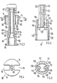
- Figur 1 eine Einspritzdüse teilweise in Seitenansicht und teilweise im Längsschnitt,
- Figur 2 einen gegenüber Figur 1 vergrößerten Längsschnitt durch den Nadelbewegungsfühler der Einspritzdüse nach Figur 1 (Line 11-11),
- Figur 3 einen Längsschnitt durch den Spulenkörper samt Spulenkern der Einspritzdüse nach Figur 1,
- Figur 4 einen Schnitt durch den Spulenkern allein nach der Linie IV - IV in Figur 3,
- Figur 5 einen Längsschnitt durch den Kabelführungskörper der Einspritzdüse nach Figur 1 und
- Figur 6 eine Ansicht des Kabelführungskörpers in Richtung des Pfeiles A in Figur 5.
- FIG. 1 shows an injection nozzle partly in side view and partly in longitudinal section,
- FIG. 2 shows a longitudinal section, enlarged compared to FIG. 1, through the needle movement sensor of the injection nozzle according to FIG. 1 (line 11-11),
- FIG. 3 shows a longitudinal section through the coil body together with the coil core of the injection nozzle according to FIG. 1,
- FIG. 4 shows a section through the coil core solely along the line IV-IV in FIG. 3,
- 5 shows a longitudinal section through the cable guide body of the injection nozzle according to FIG. 1 and
- 6 shows a view of the cable guide body in the direction of arrow A in FIG. 5.
Die Einspritzdüse hat einen Düsenhalter 10, gegen den eine Zwischenplatte 12 und ein Düsenkörper 14 durch eine Überwurfmutter 16 gespannt sind. Im Düsenkörper 14 ist eine Ventilnadel 18 verschiebbar gelagert, auf welche über ein Druckstück 20 eine Schließfeder 22 einwirkt, die in einer Federkammer 24 (Figur 2) des Düsenhalters 10 untergebracht ist. Die Schließfeder 22 stützt sich am Düsenhalter 10 über einen Stützkörper 25 ab, dessen Aufbau und Doppelfunktion nachstehend noch näher beschrieben ist.The injection nozzle has a
Die Ventilnadel 18 arbeitet mit einem nach Innen gekehrten Ventilsitz im Düsenkörper 14 zusammen und führt ihren Öffnungshub entgegen der Strömungsrichtung des Kraftstoffs aus. Die Führungsbohrung der Ventilnadel 18 ist wie üblich an einer Stelle zu einem Druckraum erweitert, in dessen Bereich die Ventilnadel 18 eine dem Ventilsitz zugekehrte Druckschulter hat und der über nicht dargestellte Kanäle im Düsenkörper 14, in der Zwischenscheibe 12 und dem Düsenhalter 10 mit einem Kraftstoff-Anschlußstutzen 26 des Düsenhalters 10 verbunden ist. Der an der Druckschulter der Ventilnadel 18 angreifende Kraftstoffdruck schiebt die Ventilnadel 18 entgegen der Kraft der Schließfeder 22 nach oben, bis eine nicht sichtbare Schulter an der Ventilnadel 18 gegen die untere Stirnseite der Zwischenscheibe 12 stößt und den weiteren Aufwärtshub der Ventilnadel 14 begrenzt.The
Im Düsenhalter 10 ist ein Nadelbewegungsfühler (Figur 2) eingebaut, der an eine Auswerteschaltung eines Steuergerätes für die Kraftstoffzufuhr oder eines Testgerätes anschließbar ist. Der Nadelbewegungsfühler besteht aus einer Induktionsspule 30 mit Wicklung 32 und Spulenkörper 34, einem Spulenkern 36, einem Ankerbolzen 38, einem durch den Stützkörper 25 gebildeten magnetischen Rückschluß und zwei Leitungsdrähten 40, 42, die durch einen Kabelführungskörpers 44 hindurchgeführt sind. Im folgenden sind die aufgeführten Teile des Nadelbewegungsfühlers näher beschrieben.A needle movement sensor (FIG. 2) is installed in the
Der Spulenkörper 34 (Figur 3) ist als KunststoffSpritzteil ausgeführt, in welches der Spulenkern 36 eingeformt ist. Der Spulenkörper 34 hat zwei Ringflansche 46, 48, die einen ersten zylindrischen Abschnitt 50 begrenzen, der die Wicklung 32 trägt. Im Ringflansch 48 sind zwei sich diametral gegenüberliegende Schlitze 52, 54 vorgesehen, durch welche die Anschlußenden der Wicklung 32 hindurchgeführt sind. Der erste zylindrische Abschnitt 50 des Spulenkörpers 34 ist über einen halsförmigen zweiten axialen Abschnitt 56 mit einem dritten, wiederum zylindrischen Abschnitt 58 verbunden, dessen Durchmesser etwa dem Durchmesser der Ringflansche 46, 48 entspricht und der mit zwei Bohrungen 60, 62 versehen ist, die mit den Schlitzen 52, 54 im Ringflansch 48 korrespondieren. Die Leitungsdrähte 40, 42 sind durch die Bohrungen 60, 62 hindurchgeführt und in den zwischen dem Ringflansch 48 und dem dritten Abschnitt 58 gebildeten Freiräumen 64, 66 mit den Anschlußenden der Wicklung 32 verbunden. An der oberen Stirnseite ist der Spulenkörper 34 mit Randansätzen 67 versehen, die, wie nachstehend noch beschrieben, zum Führen und reibungsschlüssigen Klemmen der Leitungsdrähte 40, 42 dienen.The coil former 34 (FIG. 3) is designed as a molded plastic part, into which the
Der Spulenkern 36 besteht aus Weicheisen und ist mit einer durchgehenden Bohrung 68 versehen, welche an dem einen Ende in einen konischen Abschnitt 70 übergeht. Am Außenumfang hat der Spulenkern 36 eine Ringschulter 72, die an einer Gegenschulter des Spulenkörpers 34 anliegt. Der Spulenkern 36 ist ferner mit zwei segmentförmigen Randflanschen 74 versehen, die durch Radialschlitze 76 voneinander getrennt sind und im Bereich des zylindrischen Abschnitts 58 des Spulenkörpers 34 liegen. Beim Spritzen des Spulenkörpers 34 werden die Radialschlitze 76 mit dem Material des Spulenkörpers 34 aufgefüllt und die Randflansche 74 beidseitig teilweise überdeckt, wodurch diese Teile zu einer unlösbaren Baueinheit verbunden werden.The
Die Randflansche 74 des Spulenkerns 36 ragen über den Spulenkörper 34 radial hinweg und werden durch den Stützkörper 25 gegen eine Ringschulter 78 des Düsenhalters 10 gedrückt. Der Stützkörper 25 besteht ebenfalls aus Weicheisen und ist mit einem Boden 80 versehen, der eine zentrale Bohrung hat, in welcher der Ankerbolzen 38 mit Bewegungsspiel geführt ist. Am Boden 80 des Stützkörpers 25 liegt eine aus verschleißfestem Material bestehende Ringscheibe 85 an, über welche die Stützkraft der Schließfeder 22 auf den Stützkörper 25 und weiter auf die Ringschulter 78 des Düsenhalters 10 übertragen wird.The
Der Ankerbolzen 38 besteht aus magnetisch leitendem Material und ist über ein Stangenteil 84 (Figur 1) mit dem Druckstück 20 verbunden, welches aus verschleißfestem Material besteht, oder zumindest an den Auflageflächen von Schließfeder 22 und Ventilnadel 18 mit verschleißfesten Belägen versehen ist. Das obere Ende 84 des Ankerbolzens 38 taucht in den konischen Abschnitt 70 der Bohrung 68 im Spulenkern 36 ein und ist entsprechend kegelig ausgeführt. Zwischen dem Ende 84 des Ankerbolzens 38 und der Wand des konischen Abschnitts 70 der Bohrung 68 ist ein Luftspalt im magnetischen Kreis der Induktionsspule 30 gebildet, dessen Größe sich mit dem Hub der Ventilnadel 18 ändert. Im Ankerbolzen 38 ist im Bereich der Federkammer 24 eine Querbohrung 86 vorgesehen, von welcher eine Längsbohrung 88 zum Stirnende des Ankerbolzens 38 führt.The
Die Leitungsdrähte 40, 42 sind durch einen Kabelkanal 90 im Düsenhalter 10 hindurchgeführt, der aus einem gleichachsig zur Induktionsspule 30 angeordneten zentralen Kanalabschnitt 92 und zwei äußeren Kanalabschnitten 94, 96 besteht, die als enge Bohrungen ausgeführt sind. Diese liegen sich diametral gegenüber und schließen mit dem zentralen Kanalabschnitt 92 je einen stumpfen Winkel a ein. Am äußeren Ende münden die Kanalabschnitte 94, 96 im Bereich von Ausnehmungen 98,100 im Mantel des Düsenhalters 10 aus. Jeder Kanalabschnitt 94, 96 ist durch einen O-Ring 102 und einen Kunststoffpfropfen 104 nach außen dicht verschlossen. Im Bereich der Ausnehmungen 98, 100 sind die Leitungsdrähte 40,42 in geeigneter Weise mit weiterführenden Leitungen verbunden.The
In den zentralen Kanalabschnitt 92 ist der Kabelführungskörper 44 (Figuren 5 und 6) eingesetzt, der einen zylindrischen Abschnitt 106 hat, an den sich ein im Querschnitt kreuzförmiger Abschnitt 110 anschließt. Dieser hat entsprechend seiner Querschnittsform am Mantelumfang 4 um je 90° zueinander versetzte Leisten 112, die je an einer Schulter 114 in den zylindrischen Abschnitt 106 übergehen. In zwei gegenüberliegenden Leisten 112 sind axiale Bohrungen 116, 118 für den Durchtritt der Leitungsdrähte 40, 42 vorgesehen, deren Parallelabstand kleiner als jener der Bohrungen 60, 65 im Spulenkörper 34 ist.In the
An den Abschnitt 110 des Kabelführungskörpers 44 ist ein zylindrischer Abschnitt 120 angesetzt, dessen Durchmesser etwa dem Parallelabstand der Bohrungen 116, 118 entspricht. Diese setzen sich im Abschnitt 120 als Nuten 122, 124 mit etwa halbkreisförmigen Querschnitt fort, welche ebenfalls der Kabelführung dienen. Die Länge des Abschnitts 120 ist so bemessen, daß der Kabelführungskörper 44 den größten Teil des zentralen Kanalabschnittes 92 ausfüllt. Im Abschnitt 106 des Kabelführungskörpers 44 sind innen zwei sich diametral gegenüberliegende Wandnuten 126, 128 zur Führung der Leitungsdrähte 40, 42 gebildet.A
Der zentrale Kanalabschnitt 92 des Kabelkanals 90 bildet zusammen mit den Bohrungen 86, 88 im Ankerbolzen 38, die Bohrung 68 im Spulenkern 36 und Durchbrüchen 129 im Kabelführungskörper 44 einen Leckölkanal, welcher von der Federkammer 24 in die Bohruhg 130 eines am Düsenhalter 10 befestigten Leckölanschlußstutzen 132 führt.The
Der Einbau des Nadelbewegungsfühlers in den Düsenhalter 10 geht so vor sich, daß zunächst die blanken Leitungsdrähte 40, 42 durch die Bohrungen 60, 62 im Spulenkörper 34 hindurchgeführt und mit den Anschlußenden der Wicklung 32 verbunden werden. Sodann wird der Kabelführungskörper 44 auf die Leitungsdrähte 40, 42 aufgesteckt und so weit vorgeschoben, bis er am Spulenkörper 34 anliegt. Dabei werden die Leitungsdrähte 40, 42 im Übergangsbereich zwischen den Teilen stark abgekröpft, wodurch sich selbsttätig eine Zugentlastung für die Verbindungen mit den Anschlußenden der Wicklung 32 ergibt. Diese Wirkung wird durch die am Spulenkörper 34 angeformten Ansätze 67 unterstützt. Gegebenenfalls kann auch der Kabelführungskörper 67 in Bereich seines zylindrischen Abschnitts 106 mit entsprechenden Ansätzen versehen sein, die derart auf den Spulenkörper abgestimmt sind, daß die Leitungsdrähte in diesem Bereich nach dem Zusammenbau der Einspritzdüse eine leichte Quetschung erfahren.The installation of the needle movement sensor in the
Nach dem Aufstecken des Kabelführungskörpers 44 wird über dessen zylindrischen Abschnitt 120 und die in den Nuten 122, 124 liegenden Abschnitte der Leitungsdrähte 40, 42 ein Schrumpfschlauch 134 aufgezogen, an dessen Stelle auch ein entsprechend geformter Kunststoffkörper verwendet werden könnte. Dann werden auf die aus dem Kabelführungskörper bzw. den Schrumpfschlauch 134 herausragenden Endabschnitte der Leitungsdrähte 40, 42 Isolierhüllen 136, 138 aufgeschoben, die so lang bemessen sind, daß sie nach dem Einbau der Teile bis nahe an die O-Ringe 102 reichen.After attaching the cable guide body 44 is over the
Die so vorgefertigte Baugruppe kann danach als Ganzes in den Düsenhalter 10 eingesteckt werden, bis die Randflansche 74 des Spulenkerns 36 an der Schulter 78 und die Schultern 114 am Kabelführungskörper 44 an einer Ringschulter 140 des Düsenhalters 10 zur Anlage kommen. Beim Einstecken der Baugruppe in den Düsenhalter 10 fädeln sich die beiden Endabschnitte der Leitungsdrähte 40, 42 ohne nennenswerte Hemmung in die beiden äußeren Kanalabschnitte 94, 96 des Kabelkanals 90 ein, wodurch der Zusammenbau weiter erleichtert wird. Beim Anbau der Zwischenplatte 12 und des Düsenkörpers 14 tritt der Ankerbolzen 38 durch die Bohrung im Stützkörper 25 hindurch und kommt an den Spulenkern 36 bis auf den gewünschten Luftspalt heran. Die Schließfeder 22 stützt sich über den Stützkörper 25 und die Randflansche 74 des Spulenkerns 36 auf der Schulter 78 des Düsenhalters 10 ab und hält so die Teile des Nadelbewegungsfühlers gleichzeitig spiellos fest.The assembly thus prefabricated can then be inserted as a whole into the
Die konische Ausbildung des Stirnendes 84 des Ankerbolzens 38 und des Bohrungsabschnittes 70 im Spulenkern 36 gestattet es, den Durchmesser des Nadelbewegungsfühlers klein zu halten und ergibt bezüglich der Luftspaltbemessung eine relativ toleranzunempfindliche Ausführung, so daß sich in vielen Fällen besondere Mittel zum Einjustieren des Luftspaltes erübrigen.The conical design of the
Claims (8)
Priority Applications (1)
| Application Number | Priority Date | Filing Date | Title |
|---|---|---|---|
| AT86900745T ATE36378T1 (en) | 1985-04-27 | 1986-01-30 | FUEL INJECTION NOZZLE FOR COMBUSTION ENGINES. |
Applications Claiming Priority (2)
| Application Number | Priority Date | Filing Date | Title |
|---|---|---|---|
| DE3515264 | 1985-04-27 | ||
| DE19853515264 DE3515264A1 (en) | 1985-04-27 | 1985-04-27 | FUEL INJECTION NOZZLE FOR INTERNAL COMBUSTION ENGINES |
Publications (2)
| Publication Number | Publication Date |
|---|---|
| EP0220197A1 EP0220197A1 (en) | 1987-05-06 |
| EP0220197B1 true EP0220197B1 (en) | 1988-08-10 |
Family
ID=6269282
Family Applications (1)
| Application Number | Title | Priority Date | Filing Date |
|---|---|---|---|
| EP86900745A Expired EP0220197B1 (en) | 1985-04-27 | 1986-01-30 | Fuel injection nozzle for internal combustion engines |
Country Status (7)
| Country | Link |
|---|---|
| US (1) | US4770346A (en) |
| EP (1) | EP0220197B1 (en) |
| JP (1) | JPS62502627A (en) |
| KR (1) | KR930011563B1 (en) |
| AT (1) | ATE36378T1 (en) |
| DE (2) | DE3515264A1 (en) |
| WO (1) | WO1986006442A1 (en) |
Families Citing this family (14)
| Publication number | Priority date | Publication date | Assignee | Title |
|---|---|---|---|---|
| GB8516127D0 (en) * | 1985-06-26 | 1985-07-31 | Lucas Ind Plc | Fuel injection nozzle |
| DE3840339A1 (en) * | 1988-11-30 | 1990-05-31 | Bosch Gmbh Robert | FUEL INJECTION NOZZLE FOR INTERNAL COMBUSTION ENGINES |
| US5738071A (en) * | 1991-05-22 | 1998-04-14 | Wolff Controls Corporation | Apparatus and method for sensing movement of fuel injector valve |
| US5640987A (en) * | 1994-04-05 | 1997-06-24 | Sturman; Oded E. | Digital two, three, and four way solenoid control valves |
| US5598871A (en) * | 1994-04-05 | 1997-02-04 | Sturman Industries | Static and dynamic pressure balance double flow three-way control valve |
| US6257499B1 (en) | 1994-06-06 | 2001-07-10 | Oded E. Sturman | High speed fuel injector |
| US6161770A (en) | 1994-06-06 | 2000-12-19 | Sturman; Oded E. | Hydraulically driven springless fuel injector |
| US5485957A (en) * | 1994-08-05 | 1996-01-23 | Sturman; Oded E. | Fuel injector with an internal pump |
| US5634598A (en) * | 1994-09-20 | 1997-06-03 | Minerals Technologies, Inc. | Abrasion resistant lined sweep nozzle |
| US5720261A (en) * | 1994-12-01 | 1998-02-24 | Oded E. Sturman | Valve controller systems and methods and fuel injection systems utilizing the same |
| US6148778A (en) | 1995-05-17 | 2000-11-21 | Sturman Industries, Inc. | Air-fuel module adapted for an internal combustion engine |
| US5641148A (en) * | 1996-01-11 | 1997-06-24 | Sturman Industries | Solenoid operated pressure balanced valve |
| US6085991A (en) | 1998-05-14 | 2000-07-11 | Sturman; Oded E. | Intensified fuel injector having a lateral drain passage |
| JP4735735B2 (en) | 2009-04-21 | 2011-07-27 | 株式会社デンソー | Injector |
Citations (1)
| Publication number | Priority date | Publication date | Assignee | Title |
|---|---|---|---|---|
| DE3227989A1 (en) * | 1982-07-27 | 1984-02-02 | Robert Bosch Gmbh, 7000 Stuttgart | FUEL INJECTION NOZZLE FOR INTERNAL COMBUSTION ENGINES |
Family Cites Families (9)
| Publication number | Priority date | Publication date | Assignee | Title |
|---|---|---|---|---|
| GB754917A (en) * | 1953-11-04 | 1956-08-15 | Daimler Benz Ag | Apparatus for measuring the movement of valve needles, particularly for fuel injection nozzles of internal combustion engines |
| US3596507A (en) * | 1968-08-20 | 1971-08-03 | Toyoda Chuo Kenkyusho Kk | Apparatus for detecting the injection timing of an internal combustion engine |
| SU964457A2 (en) * | 1978-09-06 | 1982-10-07 | Предприятие П/Я Р-6194 | Device for measuring fuel consumption of ic engine |
| DE3040811A1 (en) * | 1980-10-30 | 1982-06-16 | Robert Bosch Gmbh, 7000 Stuttgart | FUEL INJECTION NOZZLE FOR INTERNAL COMBUSTION ENGINES, ESPECIALLY FOR DIESEL ENGINES |
| DE3117779A1 (en) * | 1981-05-06 | 1982-11-25 | Robert Bosch Gmbh, 7000 Stuttgart | "FUEL INJECTION NOZZLE FOR INTERNAL COMBUSTION ENGINES" |
| DE3125884A1 (en) * | 1981-07-01 | 1983-01-20 | Robert Bosch Gmbh, 7000 Stuttgart | FUEL INJECTION NOZZLE FOR INTERNAL COMBUSTION ENGINES |
| JPS6036772A (en) * | 1983-08-10 | 1985-02-25 | Diesel Kiki Co Ltd | Fuel injection valve |
| DE3343269C1 (en) * | 1983-11-30 | 1985-04-04 | Daimler-Benz Ag, 7000 Stuttgart | Device for indirect contactless electrical measurement of small distances |
| US4573349A (en) * | 1984-06-28 | 1986-03-04 | International Harvester Company | Needle position indicator for a fuel injection nozzle holder |
-
1985
- 1985-04-27 DE DE19853515264 patent/DE3515264A1/en not_active Withdrawn
-
1986
- 1986-01-30 AT AT86900745T patent/ATE36378T1/en active
- 1986-01-30 DE DE8686900745T patent/DE3660507D1/en not_active Expired
- 1986-01-30 KR KR1019860700839A patent/KR930011563B1/en not_active Expired - Lifetime
- 1986-01-30 EP EP86900745A patent/EP0220197B1/en not_active Expired
- 1986-01-30 US US07/004,474 patent/US4770346A/en not_active Expired - Fee Related
- 1986-01-30 WO PCT/DE1986/000030 patent/WO1986006442A1/en not_active Ceased
- 1986-01-30 JP JP61500882A patent/JPS62502627A/en active Pending
Patent Citations (1)
| Publication number | Priority date | Publication date | Assignee | Title |
|---|---|---|---|---|
| DE3227989A1 (en) * | 1982-07-27 | 1984-02-02 | Robert Bosch Gmbh, 7000 Stuttgart | FUEL INJECTION NOZZLE FOR INTERNAL COMBUSTION ENGINES |
Also Published As
| Publication number | Publication date |
|---|---|
| US4770346A (en) | 1988-09-13 |
| KR930011563B1 (en) | 1993-12-11 |
| DE3660507D1 (en) | 1988-09-15 |
| ATE36378T1 (en) | 1988-08-15 |
| EP0220197A1 (en) | 1987-05-06 |
| KR880700164A (en) | 1988-02-20 |
| JPS62502627A (en) | 1987-10-08 |
| WO1986006442A1 (en) | 1986-11-06 |
| DE3515264A1 (en) | 1986-11-27 |
Similar Documents
| Publication | Publication Date | Title |
|---|---|---|
| EP0220197B1 (en) | Fuel injection nozzle for internal combustion engines | |
| EP0316581B1 (en) | Fuel injection pump for internal-combustion engines | |
| DE3544575C2 (en) | ||
| DE19857528A1 (en) | Connector for coaxial cable with ring-corrugated outer conductor | |
| DE3536352A1 (en) | MAGNETIC COIL | |
| DE3880631T2 (en) | ELECTROMAGNETIC VALVE. | |
| DE4428869A1 (en) | Solenoid valve | |
| DE10312824B4 (en) | Magnetic-inductive flowmeter | |
| EP0906632B1 (en) | Magnetic coil | |
| DE102020210228A1 (en) | Electromagnetic drive device, associated manufacturing method and solenoid valve device | |
| EP0446201B1 (en) | Fuel injection nozzle for internal combustion engines | |
| DE2550245A1 (en) | CONNECTING CLAMP FOR A DEVICE OR ELEMENT FOR ELECTRICAL CONNECTION | |
| DE3110660A1 (en) | SET FOR THE END OF A MEDIUM-VOLTAGE OR HIGH-VOLTAGE CABLE | |
| DE19707587B4 (en) | Electromagnetic actuator | |
| DE102008017764B4 (en) | Valve | |
| DE4341087C2 (en) | Sealed switching device | |
| EP0346587A2 (en) | Cable feedthrough | |
| EP0068339B1 (en) | Fuel injection nozzle for internal-combustion engines | |
| EP0876552B1 (en) | Distributor device for fuel injection systems | |
| DE19709044C2 (en) | linear motor | |
| EP1382047B1 (en) | Magnet coil arrangement | |
| DE10305111A1 (en) | Ignition coil for an internal combustion engine | |
| DE4108416C2 (en) | Fuel injection nozzle for internal combustion engines | |
| DE3705587C2 (en) | Electromagnetically operated valve, in particular fuel injection valve | |
| DE3502112A1 (en) | DEVICE FOR INJECTING FUEL INTO THE COMBUSTION CHAMBER OF AN INTERNAL COMBUSTION ENGINE |
Legal Events
| Date | Code | Title | Description |
|---|---|---|---|
| PUAI | Public reference made under article 153(3) epc to a published international application that has entered the european phase |
Free format text: ORIGINAL CODE: 0009012 |
|
| 17P | Request for examination filed |
Effective date: 19861114 |
|
| AK | Designated contracting states |
Kind code of ref document: A1 Designated state(s): AT DE FR GB IT |
|
| 17Q | First examination report despatched |
Effective date: 19870729 |
|
| GRAA | (expected) grant |
Free format text: ORIGINAL CODE: 0009210 |
|
| AK | Designated contracting states |
Kind code of ref document: B1 Designated state(s): AT DE FR GB IT |
|
| REF | Corresponds to: |
Ref document number: 36378 Country of ref document: AT Date of ref document: 19880815 Kind code of ref document: T |
|
| GBT | Gb: translation of ep patent filed (gb section 77(6)(a)/1977) | ||
| REF | Corresponds to: |
Ref document number: 3660507 Country of ref document: DE Date of ref document: 19880915 |
|
| ET | Fr: translation filed | ||
| ITF | It: translation for a ep patent filed | ||
| PLBE | No opposition filed within time limit |
Free format text: ORIGINAL CODE: 0009261 |
|
| STAA | Information on the status of an ep patent application or granted ep patent |
Free format text: STATUS: NO OPPOSITION FILED WITHIN TIME LIMIT |
|
| 26N | No opposition filed | ||
| ITTA | It: last paid annual fee | ||
| PGFP | Annual fee paid to national office [announced via postgrant information from national office to epo] |
Ref country code: DE Payment date: 19910327 Year of fee payment: 6 |
|
| PGFP | Annual fee paid to national office [announced via postgrant information from national office to epo] |
Ref country code: GB Payment date: 19920117 Year of fee payment: 7 |
|
| PGFP | Annual fee paid to national office [announced via postgrant information from national office to epo] |
Ref country code: AT Payment date: 19920123 Year of fee payment: 7 |
|
| PGFP | Annual fee paid to national office [announced via postgrant information from national office to epo] |
Ref country code: FR Payment date: 19920130 Year of fee payment: 7 |
|
| PG25 | Lapsed in a contracting state [announced via postgrant information from national office to epo] |
Ref country code: DE Effective date: 19921001 |
|
| PG25 | Lapsed in a contracting state [announced via postgrant information from national office to epo] |
Ref country code: GB Effective date: 19930130 Ref country code: AT Effective date: 19930130 |
|
| GBPC | Gb: european patent ceased through non-payment of renewal fee |
Effective date: 19930130 |
|
| PG25 | Lapsed in a contracting state [announced via postgrant information from national office to epo] |
Ref country code: FR Effective date: 19930930 |
|
| REG | Reference to a national code |
Ref country code: FR Ref legal event code: ST |
|
| PG25 | Lapsed in a contracting state [announced via postgrant information from national office to epo] |
Ref country code: IT Free format text: LAPSE BECAUSE OF NON-PAYMENT OF DUE FEES;WARNING: LAPSES OF ITALIAN PATENTS WITH EFFECTIVE DATE BEFORE 2007 MAY HAVE OCCURRED AT ANY TIME BEFORE 2007. THE CORRECT EFFECTIVE DATE MAY BE DIFFERENT FROM THE ONE RECORDED. Effective date: 20050130 |