EP0220163A2 - Panel for the exterior wall of a building - Google Patents
Panel for the exterior wall of a building Download PDFInfo
- Publication number
- EP0220163A2 EP0220163A2 EP86890249A EP86890249A EP0220163A2 EP 0220163 A2 EP0220163 A2 EP 0220163A2 EP 86890249 A EP86890249 A EP 86890249A EP 86890249 A EP86890249 A EP 86890249A EP 0220163 A2 EP0220163 A2 EP 0220163A2
- Authority
- EP
- European Patent Office
- Prior art keywords
- edge
- web
- building
- panel
- board
- Prior art date
- Legal status (The legal status is an assumption and is not a legal conclusion. Google has not performed a legal analysis and makes no representation as to the accuracy of the status listed.)
- Granted
Links
Images
Classifications
-
- E—FIXED CONSTRUCTIONS
- E04—BUILDING
- E04B—GENERAL BUILDING CONSTRUCTIONS; WALLS, e.g. PARTITIONS; ROOFS; FLOORS; CEILINGS; INSULATION OR OTHER PROTECTION OF BUILDINGS
- E04B2/00—Walls, e.g. partitions, for buildings; Wall construction with regard to insulation; Connections specially adapted to walls
- E04B2/88—Curtain walls
- E04B2/90—Curtain walls comprising panels directly attached to the structure
- E04B2/92—Sandwich-type panels
-
- E—FIXED CONSTRUCTIONS
- E04—BUILDING
- E04F—FINISHING WORK ON BUILDINGS, e.g. STAIRS, FLOORS
- E04F13/00—Coverings or linings, e.g. for walls or ceilings
- E04F13/07—Coverings or linings, e.g. for walls or ceilings composed of covering or lining elements; Sub-structures therefor; Fastening means therefor
- E04F13/08—Coverings or linings, e.g. for walls or ceilings composed of covering or lining elements; Sub-structures therefor; Fastening means therefor composed of a plurality of similar covering or lining elements
- E04F13/0801—Separate fastening elements
- E04F13/0803—Separate fastening elements with load-supporting elongated furring elements between wall and covering elements
- E04F13/081—Separate fastening elements with load-supporting elongated furring elements between wall and covering elements with additional fastening elements between furring elements and covering elements
- E04F13/0814—Separate fastening elements with load-supporting elongated furring elements between wall and covering elements with additional fastening elements between furring elements and covering elements fixed by means of clamping action
Landscapes
- Engineering & Computer Science (AREA)
- Architecture (AREA)
- Civil Engineering (AREA)
- Structural Engineering (AREA)
- Physics & Mathematics (AREA)
- Electromagnetism (AREA)
- Building Environments (AREA)
Abstract
Description
Die Erfindung bezieht sich auf eine Bauplatte für die Außenwand eines Gebäudes mit auf der Platteninnenseite zumindest im Bereich der vertikalen Plattenränder vorgesehenen Randprofilen, die einen mit Abstand vom Plattenrand und parallel zu diesem verlaufenden, abstehenden Steg mit einem abgewinkelten Befestigungflansch auf der dem Plattenrand abgewandten Seite aufweisen.The invention relates to a building board for the outer wall of a building with edge profiles provided on the inside of the board at least in the area of the vertical board edges, which have a projecting web at a distance from and parallel to the board edge with an angled fastening flange on the side facing away from the board edge .
Bei bekannten Bauplatten dieser Art (DE-OS 2 445 785) dienen die abgewinkelten Befestigungsflansche der mit der Bewehrung der Bauplatten verbundenen Stege zur Verbindung der zu einer Wand nebeneinandergereihten Bauplatten mit Hilfe von Streben, die an den Befestigungsflanschen benachbarter Bauplatten festgeschraubt werden. Diese Bauplatten sind daher nicht für eine Befestigung an vertikalen Stehern geeignet, wie sie bei Stahlskelettbauten vorgesehen sind. Bei der Befestigung von Bauplatten an vertikalen Stehern von Stahlskelettbauten muß nämlich für einen Ausgleich von Wärmedehnungen gesorgt werden, so daß ein Anschrauben der Bauplatten an den Stehern nicht in Frage kommt. Abgesehen davon bedingen Schraubverbindungen zwischen den Bauplatten und den Stehern entsprechende Gewindebohrungen in den Stehern, was nicht nur die Montage erschwert, sondern auch den tragenden Querschnitt der Steher schwächt.In known building boards of this type (DE-OS 2 445 785), the angled fastening flanges of the webs connected to the reinforcement of the building boards serve to connect the building boards lined up next to one another with the aid of struts which are screwed tightly to the fastening flanges of adjacent building boards. These building boards are therefore not suitable for attachment to vertical uprights, such as those provided for steel skeleton buildings. When attaching building boards to vertical uprights of steel skeleton structures, thermal expansion must be compensated for, so that screwing the building boards onto the uprights is out of the question. Apart from this, screw connections between the building boards and the uprights require corresponding threaded holes in the uprights, which not only complicates assembly, but also weakens the load-bearing cross-section of the uprights.
Um Wandfüllungen an vertikalen Stehern befestigen zu können, ist eine Vorrichtung bekannt (DE-AS 1 784 346), bei der eine Halterung für die zwischen den Stehern eingesetzten Wandfüllungen an den Stehern festgeklemmt wird. Diese Hal terung besteht im wesentlichen aus einem U-förmigen Bügel, der den Steher umgreift, wobei die freien Schenkel dieses Bügels durch ein Verschlußstück miteinander verbunden werden können, das gegen den Steher gedrückt wird, so daß sich zwischen dem Steher und der Halterung eine Klemmverbindung ergibt, die Bohrungen im Steher unnötig macht. Nachteilig bei dieser bekannten Konstruktion ist allerdings, daß die Wandfüllungen nur zwischen den Stehern eingesetzt werden können und keine die Steher abdeckende Wandfläche bilden. Außerdem werden beim Lösen der Halterung die beiden an den Steher anschließenden Wandfüllungen freigegeben, so daß das Austauschen einzelner Wandelemente erschwert ist.In order to be able to attach wall panels to vertical uprights, a device is known (DE-AS 1 784 346) in which a holder for the wall panels used between the uprights is clamped to the uprights. This hal Tension consists essentially of a U-shaped bracket that engages around the post, the free legs of this bracket can be connected to each other by a locking piece that is pressed against the post, so that there is a clamping connection between the post and the holder, the holes in the post unnecessary. A disadvantage of this known construction, however, is that the wall panels can only be used between the uprights and do not form a wall surface covering the uprights. In addition, when the holder is released, the two wall fillings adjoining the upright are released, so that the exchange of individual wall elements is difficult.
Der Erfindung liegt somit die Aufgabe zugrunde, diese Mängel zu vermeiden und Bauplatten der eingangs geschilderten Art so zu verbessern, daß sie einfach und sicher an vertikalen Stehern befestigt werden können, und zwar unter Abdeckung der Steher, daß Zwangskräfte zufolge von Wärmedehnungen ausgeschlossen werden und daß ein Wärmeübergang zwischen den Bauplatten und den Stehern weitgehend unterbunden wird.The invention is therefore based on the object to avoid these deficiencies and to improve building boards of the type described above so that they can be easily and securely attached to vertical uprights, and under cover of the uprights that constraining forces are excluded from thermal expansion and that heat transfer between the building boards and the uprights is largely prevented.
Die Erfindung löst die gestellte Aufgabe dadurch, daß der Steg mit dem abgewinkelten Befestigungsflansch Teil eines Z-Profiles ist, dessen gegen den Plattenrand gerichteter Schenkel einen abgewinkelten Randsteg bildet, und daß der abgewinkelte Befestigungsflansch gegen den Plattenrand vorragende Klemmstücke zum Ergreifen eines an der Stirnseite des Randsteges anliegenden Stehers trägt.The invention solves this problem in that the web with the angled mounting flange is part of a Z-profile, the leg directed against the plate edge forms an angled edge web, and in that the angled mounting flange protrudes against the plate edge clamping pieces for gripping one on the front side of the Edge pier adjoining post.
Die gegen den Plattenrand vorragenden Klemmstücke an dem abgewinkelten Befestigungsflansch erlauben im Zusammenhang mit der besonderen Form des Randprofiles eine einfache Plattenbefestigung, weil über die den Steher umgreifende Klemmstücke der Steher mit einer ausreichend großen Kraft an die Stirnseite des Randsteges des Z-Profiles angedrückt werden kann, ohne die Bauplatte selbst in einer unzulässigen Weise durch die Klemmkräfte belasten zu müssen. Die auftretenden Klemmkräfte werden ja über das Z-Profil kurzge schlossen, so daß die Bauplatte belastungsfrei bleibt. Die Klemmverbindung über die den Steher umgreifenden Klemmstücke ermöglicht eine ausreichende Relativbewegung zwischen der Bauplatte und dem Steher, um Wärmedehnungen ausgleichen und damit Zwangskräfte vermeiden zu können. Dabei bleiben die Berührungsflächen zwischen dem Steher einerseits und dem Z-Profil bzw. den Klemmstücken anderseits vergleichsweise gering, weil der Steher lediglich an der Stirnseite des Randsteges des Z-Profiles anliegt und die Auflagefläche der Klemmstücke klein gewählt werden kann. Ein unerwünschter Wärmeübergang von den Bauplatten zu den Stehern kannd daher in einem ausreichenden Maß unterbunden werden. Der auf der Platteninnenseite abstehende Randsteg des Z-Profiles erlaubt darüber hinaus eine einfache Abdeckung der Steher durch die Bauplatten selbst. Schließlich ist anzuführen, daß durch das Z-förmige Randprofil eine zusätzliche Versteifung der Bauplatte gerade im gefährdeten Randbereich erhalten wird, wodurch der Einsatz größerer bzw. leichterer Bauplatten möglich wird.The clamping pieces protruding against the edge of the plate on the angled fastening flange allow simple plate fastening in connection with the special shape of the edge profile, because the clamping pieces encompassing the upright can be used to press the upright against the front side of the edge web of the Z profile with a sufficiently large force, without having to load the building board itself in an impermissible manner by the clamping forces. The clamping forces that occur are in short over the Z profile closed so that the building board remains stress-free. The clamping connection via the clamping pieces encompassing the upright enables sufficient relative movement between the building board and the upright to compensate for thermal expansion and thus to be able to avoid constraining forces. The contact areas between the upright on the one hand and the Z-profile or the clamping pieces on the other hand remain comparatively small because the standing contact rests only on the end face of the edge web of the Z-profile and the contact surface of the clamping pieces can be chosen to be small. An undesirable heat transfer from the building boards to the uprights can therefore be prevented to a sufficient extent. The edge web of the Z-profile protruding on the inside of the panel also allows the uprights to be easily covered by the building boards themselves. Finally, it should be mentioned that the Z-shaped edge profile provides additional stiffening of the building board, especially in the endangered edge area, which increases the use or lighter building boards is possible.
Da zwischen den Bauplatten und den Stehern ein bestimmter Abstand eingehalten werden soll, ergeben sich besonders günstige Konstruktionsverhältnisse, wenn der Steg des Z-Profiles in weiterer Ausbildung der Erfindung an einer Plattenschulter anliegt, so daß durch den damit bedingten Plattenabsatz Raum für den Steher geschaffen wird, ohne die Bauplatten gegenüber den Stehern nach außen vorsetzen zu müssen.Since a certain distance is to be maintained between the building boards and the uprights, there are particularly favorable design conditions if the web of the Z-profile rests on a panel shoulder in a further embodiment of the invention, so that space for the upright is created by the resulting panel sales without having to place the building boards in front of the uprights.
Um jede Wärmebrücke zwischen der Bauplatte und dem Steher zu unterbinden, kann zwischen dem abgewinkelten Randsteg des Z-Profiles und dem Steher bzw. zwischen dem Steher und den Klemmstücken eine Wärmeisolierung, beispielsweise aus Kunststoff, vorgesehen sein. Diese Wärmeisolierung verhindert einen Wärmeübergang auch an den wenigen Berührungsflächen zwischen dem Steher und dem Z-Profil.In order to prevent any thermal bridge between the building board and the upright, thermal insulation, for example made of plastic, can be provided between the angled edge web of the Z profile and the upright or between the upright and the clamping pieces. This thermal insulation prevents heat transfer even on the few contact surfaces between the upright and the Z-profile.
Die Klemmstücke zum Festklemmen der Bauplatte an einem Steher können an sich unterschiedlich ausgebildet werden, wenn über diese Klemmstücke ausreichende Klemmkräfte auf den Steher übertragen werden können. Besonders vorteilhafte Bedingungen werden allerdings sichergestellt, wenn die Klemmstücke als zweiarmige Klemmhebel ausgebildet sind, die den Steg des Z-Profiles in einer Durchtrittsöffnung durchsetzen und eine am Befestigungsflansch abgestützte Klemmschraube aufweisen. Beim Anziehen dieser Klemmschraube legt sich nämlich der Klemmhebel an den Außenrand der Durchtrittsöffnung im Steg des Z-Profiles an, wobei dieser Öffnungsrand das Drehlager für den Klemmhebel bildet, der demzufolge gegen den Steher geschwenkt wird. Das Vorsehen der den Steg des Z-Profiles durchsetzenden Klemmhebel gewährleistet aber nicht nur einfache Montagebedingungen, sondern stellt auch vorteilhafte Verhältnisse hinsichtlich des Ausgleichs von Wärmedehnungen aufgrund seiner Verschwenkbarkeit sicher.The clamping pieces for clamping the building board to a post can be designed differently per se, if sufficient clamping forces can be transferred to the upright via these clamping pieces. Particularly advantageous conditions are ensured, however, if the clamping pieces are designed as two-armed clamping levers which pass through the web of the Z-profile in a passage opening and have a clamping screw supported on the fastening flange. When tightening this clamping screw, the clamping lever lies against the outer edge of the passage opening in the web of the Z-profile, this opening edge forming the pivot bearing for the clamping lever, which is consequently pivoted against the upright. The provision of the clamping levers passing through the web of the Z-profile not only ensures simple assembly conditions, but also ensures advantageous conditions with regard to the compensation of thermal expansion due to its pivotability.
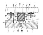
In der Zeichnung ist der Erfindungsgegenstand in einem Ausführungsbeispiel dargestellt, und zwar wird der Anschluß zweier erfindungsgemäßer Bauplatten an einem Steher eines Gebäudes in einem vereinfachten Horizontalschnitt durch den Steher gezeigt.In the drawing, the subject matter of the invention is shown in one embodiment, namely the connection of two building boards according to the invention to an upright of a building is shown in a simplified horizontal section through the upright.
Die vorzugsweise aus Schaum- oder Leichtbeton gefertigten Bauplatten 1 weisen im Bereich der vertikalen Plattenränder Randprofile 2 auf, die im Bereich der horizontalen Plattenränder zu einem Profilrahmen verbunden sind. Diese Randprofile 2 werden im wesentlichen durch ein Z-Profil gebildet, dessen randparalleler Steg 3 auf der Platteninnenseite absteht und auf der dem Plattenrand abgekehrten Seite einen abgewinkelten Befestigungsflansch 4 aufweist, der zumindest angenähert plattenparallel ausgerichtet ist. Der gegen den Plattenrand vorragende Schenkel 5 des Z-Profiles ist mit einem abgewinkelten Randsteg 6 versehen, der bündig mit dem vertikalen Plattenrand abschließt.The
Zur Befestigung der Bauplatten 1 am einem Steher 7 sind Klemmstücke 8 vorgesehen, die gemäß dem Ausführungsbeispiel als zweiarmige Klemmhebel 9 ausgebildet sind und den Steg 3 der Randprofile 2 in Durchtrittsöffnungen 10 durch setzen. Mit Hilfe von am Befestigungsflansch 4 abgestützten Klemmschrauben 11, die in eine Gewindebohrung der Klemmhebel 9 eingreifen, können diese Klemmhebel 9 betätigt werden, wobei sich beim Anziehen der Klemmschrauben 11 die Klemmhebel 9 an den äußeren Rand der Durchtrittsöffnungen 10 anlegen und um diesen Rand verschwenkt werden. Dabei wird der Steher 7 zwischen den Stirnseiten der abgewinkelten Randstege 6 und dem Klemmhebel 9 festgeklemmt und die gewünschte Klemmverbindung zwischen dem Steher 7 und den Bauplatten 1 hergestellt. Die Klemmkräfte werden über die Randprofile 2 kurzgeschlossen, so daß die Bauplatten 1 selbst belastungsfrei bleiben. Nach der Montage der Bauplatten 1 können die verbleibenden Fugen zwischen den einzelnen Bauplatten 1 durch einen Schaumstoffstreifen 12 und eine Kitschicht 13 ausgefüllt werden, was eine völlige Abdeckung der Steher 7 ergibt, ohne den Ausgleich von Wärmedehnungen zu beeinträchtigen.To attach the
Der mögliche Wärmeübergang zwischen den Bauplatten 1 und dem Steher 7 ist aufgrund der vergleichsweise geringen Berührungsflächen klein. Um jede Wärmebrücke zu unterbinden, kann zusätzlich zwischen dem Steher 7 einerseits und den abgewinkelten Randstegen 6 bzw. den Klemmstücken 8 anderseits eine Wärmeisolierung 14, beispielsweise ein Kunststoffband, vorgesehen werden, wie dies im Ausführungsbeispiel zwischen den Randstegen 6 und dem Steher 7 angedeutet ist.The possible heat transfer between the
Die abgewinkelten Randstege 6 des Z-Profiles stellen einen entsprechenden Abstand zwischen den Bauplatten 1 und dem Steher 7 in dessen Bereich sicher. Damit aufgrund dieses Abstandes nicht die gesamte Bauplatte um die Höhe des Randsteges 6 dem Steher 7 vorgesetzt werden muß, bildet die Bauplatte eine entsprechende Schulter 15, an die sich der Steg 3 des Randprofiles 2 anlegt.The
Die Befestigung der Bauplatten 1 an Stehern 7 mit Hilfe der Klemmstücke 8 stellt einen ausreichenden Abstand der Bauplatten 1 beispielsweise von einer möglichen Innenverkleidung 16 für eine Außenwandhinterlüftung sicher. Es muß in einem solchen Fall jedoch dafür gesorgt werden, daß die horizontalen Schenkel des Profilrahmens der Bauplatten 1 einen ausreichenden Luftdurchsatz ermöglichen. Zu diesem Zweck können die horizontalen Profilrahmenschenkel mit entsprechenden Luftdurchtrittsöffnungen versehen werden. Um einen freien Strömungsweg durch diese Luftdurchtrittsöffnungen zu sichern, ist es vorteilhaft, die Schulter 15 gegenüber dem abstehenden Steg der horizontalen Randprofile zurückzuversetzen, so daß zwischen der Schulter 15 und dem Steg der Randprofile ein entsprechender Strömungskanal für den Luftdurchtritt freibleibt. Bei einer solchen Ausbildung können die Bauplatten 1 durchaus über die horizontalen Rahmenschenkel abgestützt werden, ohne die Hinterlüftung der Außenwand zu beeinträchtigen.The fastening of the
Soll eine der Bauplatten 1 ausgetauscht werden, so ist dies ohne weiteres möglich, weil jede der Bauplatten 1 für sich unabhängig von den anschließenden Bauplatten mit dem Steher verbunden ist. Es kann foglich auch jede Bauplatte für sich von den Stehern gelöst werden, indem die ihr zugehörigen Klemmstücke 9 gelockert werden.If one of the
Die Randprofile 2 sind, wie dies üblich ist, mit der Plattenbewehrung verbunden, was allerdings aus Übersichtlichkeitsgründen nicht näher dargestellt ist.The
Claims (4)
Applications Claiming Priority (2)
| Application Number | Priority Date | Filing Date | Title |
|---|---|---|---|
| AT302685A AT383172B (en) | 1985-10-18 | 1985-10-18 | BUILDING PANEL FOR THE EXTERNAL WALL OF A BUILDING |
| AT3026/85 | 1985-10-18 |
Publications (3)
| Publication Number | Publication Date |
|---|---|
| EP0220163A2 true EP0220163A2 (en) | 1987-04-29 |
| EP0220163A3 EP0220163A3 (en) | 1988-08-17 |
| EP0220163B1 EP0220163B1 (en) | 1990-08-29 |
Family
ID=3544149
Family Applications (1)
| Application Number | Title | Priority Date | Filing Date |
|---|---|---|---|
| EP19860890249 Expired - Lifetime EP0220163B1 (en) | 1985-10-18 | 1986-09-08 | Panel for the exterior wall of a building |
Country Status (3)
| Country | Link |
|---|---|
| EP (1) | EP0220163B1 (en) |
| AT (1) | AT383172B (en) |
| DE (1) | DE3673748D1 (en) |
Cited By (1)
| Publication number | Priority date | Publication date | Assignee | Title |
|---|---|---|---|---|
| CN111827528A (en) * | 2020-06-29 | 2020-10-27 | 北新集团建材股份有限公司 | Vibration reduction keel, sound insulation wall unit and sound insulation wall |
Citations (6)
| Publication number | Priority date | Publication date | Assignee | Title |
|---|---|---|---|---|
| FR778686A (en) * | 1933-12-07 | 1935-03-22 | New processes for building construction | |
| FR810491A (en) * | 1936-09-07 | 1937-03-22 | Fibre Diamond | Method for fixing cover plates obtained by molding sheet materials |
| US2145469A (en) * | 1937-08-18 | 1939-01-31 | Merle C Scanland | Ornamental wall panel and means for securing the same |
| US2163381A (en) * | 1938-02-23 | 1939-06-20 | Marsan Edward Paul | Self-locking building block |
| US3065831A (en) * | 1959-04-24 | 1962-11-27 | Armco Steel Corp | Panel for curtain walls |
| FR1494247A (en) * | 1966-07-26 | 1967-09-08 | Chantiers De Nantes Atel | Sealing device for facade panel |
-
1985
- 1985-10-18 AT AT302685A patent/AT383172B/en not_active IP Right Cessation
-
1986
- 1986-09-08 DE DE8686890249T patent/DE3673748D1/en not_active Expired - Fee Related
- 1986-09-08 EP EP19860890249 patent/EP0220163B1/en not_active Expired - Lifetime
Patent Citations (6)
| Publication number | Priority date | Publication date | Assignee | Title |
|---|---|---|---|---|
| FR778686A (en) * | 1933-12-07 | 1935-03-22 | New processes for building construction | |
| FR810491A (en) * | 1936-09-07 | 1937-03-22 | Fibre Diamond | Method for fixing cover plates obtained by molding sheet materials |
| US2145469A (en) * | 1937-08-18 | 1939-01-31 | Merle C Scanland | Ornamental wall panel and means for securing the same |
| US2163381A (en) * | 1938-02-23 | 1939-06-20 | Marsan Edward Paul | Self-locking building block |
| US3065831A (en) * | 1959-04-24 | 1962-11-27 | Armco Steel Corp | Panel for curtain walls |
| FR1494247A (en) * | 1966-07-26 | 1967-09-08 | Chantiers De Nantes Atel | Sealing device for facade panel |
Cited By (1)
| Publication number | Priority date | Publication date | Assignee | Title |
|---|---|---|---|---|
| CN111827528A (en) * | 2020-06-29 | 2020-10-27 | 北新集团建材股份有限公司 | Vibration reduction keel, sound insulation wall unit and sound insulation wall |
Also Published As
| Publication number | Publication date |
|---|---|
| EP0220163B1 (en) | 1990-08-29 |
| DE3673748D1 (en) | 1990-10-04 |
| AT383172B (en) | 1987-05-25 |
| EP0220163A3 (en) | 1988-08-17 |
| ATA302685A (en) | 1986-10-15 |
Similar Documents
| Publication | Publication Date | Title |
|---|---|---|
| DE4006605C1 (en) | Prefabricated sectional room - has floor with transverse support frame having composite sidewalls carrying appliances | |
| DE2636531A1 (en) | Prefabricated hollow wall building panel - has disc extensions glued to panel inside and spacer bar ends | |
| DE3815140A1 (en) | Joint shuttering for glass structural elements which comprise a plurality of glass elements, in particular glass blocks | |
| DE1409988A1 (en) | Method for fastening ceiling joists to so-called suspended ceilings | |
| EP0281957A1 (en) | Segment-shaped basin | |
| EP0220163B1 (en) | Panel for the exterior wall of a building | |
| AT401788B (en) | FACADE | |
| DE2644559A1 (en) | EXTENDABLE AND CONVERTIBLE PARTITION WALL | |
| DE1459901C3 (en) | Building that has a front with loggias | |
| DE3415848A1 (en) | Rail vehicle | |
| DE1931427C3 (en) | Wall construction for buildings | |
| DE3822940C2 (en) | ||
| DE3310284A1 (en) | Standard dwelling container | |
| EP0752508A2 (en) | Façade covering | |
| DE1805979C (en) | Cladding panel made of asbestos cement for walls or the like | |
| DE3809020C2 (en) | ||
| EP0474951B1 (en) | Rectangular sheet-iron façade element | |
| DE19828480A1 (en) | Building panel with support frame | |
| EP1574632A2 (en) | Dry wall | |
| EP1319790A2 (en) | Anchor for door and window | |
| DE3729378A1 (en) | WORKTOP UNIT | |
| DE19501088A1 (en) | Corner posts for wall cladding made of cladding elements provided with a plastic frame | |
| DE19625315A1 (en) | Wall cladding system for bathrooms and kitchens - involves angled profiles and spacer bent in-situ to suit wall interval in sequence of installation stages | |
| DE29825071U1 (en) | Building panel with support frame | |
| DE2120485A1 (en) | Device for aligning and holding prefabricated walls |
Legal Events
| Date | Code | Title | Description |
|---|---|---|---|
| PUAI | Public reference made under article 153(3) epc to a published international application that has entered the european phase |
Free format text: ORIGINAL CODE: 0009012 |
|
| AK | Designated contracting states |
Kind code of ref document: A2 Designated state(s): BE CH DE FR GB IT LI NL SE |
|
| PUAL | Search report despatched |
Free format text: ORIGINAL CODE: 0009013 |
|
| AK | Designated contracting states |
Kind code of ref document: A3 Designated state(s): BE CH DE FR GB IT LI NL SE |
|
| 17P | Request for examination filed |
Effective date: 19880915 |
|
| 17Q | First examination report despatched |
Effective date: 19900207 |
|
| GRAA | (expected) grant |
Free format text: ORIGINAL CODE: 0009210 |
|
| AK | Designated contracting states |
Kind code of ref document: B1 Designated state(s): BE CH DE FR GB IT LI NL SE |
|
| PG25 | Lapsed in a contracting state [announced via postgrant information from national office to epo] |
Ref country code: IT Free format text: LAPSE BECAUSE OF FAILURE TO SUBMIT A TRANSLATION OF THE DESCRIPTION OR TO PAY THE FEE WITHIN THE PRE;WARNING: LAPSES OF ITALIAN PATENTS WITH EFFECTIVE DATE BEFORE 2007 MAY HAVE OCCURRED AT ANY TIME BEFORE 2007. THE CORRECT EFFECTIVE DATE MAY BE DIFFERENT FROM THE ONE RECORDED.SCRIBED TIME-LIMIT Effective date: 19900829 Ref country code: BE Effective date: 19900829 Ref country code: SE Free format text: THE PATENT HAS BEEN ANNULLED BY A DECISION OF A NATIONAL AUTHORITY Effective date: 19900829 Ref country code: NL Effective date: 19900829 Ref country code: FR Effective date: 19900829 Ref country code: GB Effective date: 19900829 |
|
| PG25 | Lapsed in a contracting state [announced via postgrant information from national office to epo] |
Ref country code: LI Effective date: 19900930 Ref country code: CH Effective date: 19900930 |
|
| REF | Corresponds to: |
Ref document number: 3673748 Country of ref document: DE Date of ref document: 19901004 |
|
| EN | Fr: translation not filed | ||
| NLV1 | Nl: lapsed or annulled due to failure to fulfill the requirements of art. 29p and 29m of the patents act | ||
| GBV | Gb: ep patent (uk) treated as always having been void in accordance with gb section 77(7)/1977 [no translation filed] | ||
| REG | Reference to a national code |
Ref country code: CH Ref legal event code: PL |
|
| PG25 | Lapsed in a contracting state [announced via postgrant information from national office to epo] |
Ref country code: DE Effective date: 19910601 |
|
| PLBE | No opposition filed within time limit |
Free format text: ORIGINAL CODE: 0009261 |
|
| STAA | Information on the status of an ep patent application or granted ep patent |
Free format text: STATUS: NO OPPOSITION FILED WITHIN TIME LIMIT |
|
| 26N | No opposition filed |