EP0219986A1 - Apparatus for preventing the formation of deposits on vertical heat exchanger walls - Google Patents
Apparatus for preventing the formation of deposits on vertical heat exchanger walls Download PDFInfo
- Publication number
- EP0219986A1 EP0219986A1 EP86307355A EP86307355A EP0219986A1 EP 0219986 A1 EP0219986 A1 EP 0219986A1 EP 86307355 A EP86307355 A EP 86307355A EP 86307355 A EP86307355 A EP 86307355A EP 0219986 A1 EP0219986 A1 EP 0219986A1
- Authority
- EP
- European Patent Office
- Prior art keywords
- duct
- wall
- chain
- cleaner member
- elongate
- Prior art date
- Legal status (The legal status is an assumption and is not a legal conclusion. Google has not performed a legal analysis and makes no representation as to the accuracy of the status listed.)
- Withdrawn
Links
- 230000015572 biosynthetic process Effects 0.000 title 1
- 239000013618 particulate matter Substances 0.000 claims description 5
- 238000009825 accumulation Methods 0.000 claims description 2
- 229910052729 chemical element Inorganic materials 0.000 claims description 2
- 230000033001 locomotion Effects 0.000 abstract description 17
- 239000007789 gas Substances 0.000 abstract description 11
- 239000000567 combustion gas Substances 0.000 abstract description 9
- 210000005244 lower chamber Anatomy 0.000 abstract 3
- 238000000151 deposition Methods 0.000 abstract 1
- 239000011236 particulate material Substances 0.000 abstract 1
- 239000000779 smoke Substances 0.000 description 13
- 210000003414 extremity Anatomy 0.000 description 7
- 239000002956 ash Substances 0.000 description 3
- 230000000694 effects Effects 0.000 description 3
- 238000004140 cleaning Methods 0.000 description 2
- 239000003245 coal Substances 0.000 description 2
- 239000000446 fuel Substances 0.000 description 2
- 230000007246 mechanism Effects 0.000 description 2
- 239000004071 soot Substances 0.000 description 2
- 210000001364 upper extremity Anatomy 0.000 description 2
- 241001589086 Bellapiscis medius Species 0.000 description 1
- YUBJPYNSGLJZPQ-UHFFFAOYSA-N Dithiopyr Chemical compound CSC(=O)C1=C(C(F)F)N=C(C(F)(F)F)C(C(=O)SC)=C1CC(C)C YUBJPYNSGLJZPQ-UHFFFAOYSA-N 0.000 description 1
- 235000002918 Fraxinus excelsior Nutrition 0.000 description 1
- 238000005452 bending Methods 0.000 description 1
- 238000010304 firing Methods 0.000 description 1
- 239000000727 fraction Substances 0.000 description 1
- 238000012423 maintenance Methods 0.000 description 1
- 239000002184 metal Substances 0.000 description 1
- 230000010355 oscillation Effects 0.000 description 1
- 238000005192 partition Methods 0.000 description 1
- 230000002093 peripheral effect Effects 0.000 description 1
- 230000002035 prolonged effect Effects 0.000 description 1
- 239000007787 solid Substances 0.000 description 1
- 238000003466 welding Methods 0.000 description 1
Images
Classifications
-
- F—MECHANICAL ENGINEERING; LIGHTING; HEATING; WEAPONS; BLASTING
- F28—HEAT EXCHANGE IN GENERAL
- F28G—CLEANING OF INTERNAL OR EXTERNAL SURFACES OF HEAT-EXCHANGE OR HEAT-TRANSFER CONDUITS, e.g. WATER TUBES OR BOILERS
- F28G3/00—Rotary appliances
- F28G3/06—Rotary appliances having articulated tools, e.g. assembled in chain manner
-
- F—MECHANICAL ENGINEERING; LIGHTING; HEATING; WEAPONS; BLASTING
- F28—HEAT EXCHANGE IN GENERAL
- F28F—DETAILS OF HEAT-EXCHANGE AND HEAT-TRANSFER APPARATUS, OF GENERAL APPLICATION
- F28F19/00—Preventing the formation of deposits or corrosion, e.g. by using filters or scrapers
-
- F—MECHANICAL ENGINEERING; LIGHTING; HEATING; WEAPONS; BLASTING
- F28—HEAT EXCHANGE IN GENERAL
- F28G—CLEANING OF INTERNAL OR EXTERNAL SURFACES OF HEAT-EXCHANGE OR HEAT-TRANSFER CONDUITS, e.g. WATER TUBES OR BOILERS
- F28G1/00—Non-rotary, e.g. reciprocated, appliances
- F28G1/04—Non-rotary, e.g. reciprocated, appliances having articulated tools, e.g. assembled in chain manner
Definitions
- the present invention relates to an apparatus or appliance for preventing particulate matter entrained in a gas flowing through vertical ducts of a boiler or other heat exchanger, from accumulating in the form of unwanted deposits on the5duct walls.
- Danish patent specification No. l29,875 discloses an apparatus for cleaning vertical fire or smoke tubes of a boiler or other heat exchanger, which apparatus comprises a sheet metal screw extending through the height of each tube with a small clearance between the inner tube wall and the peripheral edge of the screw flight.
- Each screw is suspended from a carrier located above the associated tube and coupled to a drive mechanism adapted to impart a vertically reciprocating movement to the screw at suitable intervals. Due to the clearance within the tube the vertical movement of the screw will be accompanied by small lateral movements whereby the edge of the screw collides with the tube wall and exerts a combined impact and scraper effect on deposits present on the wall.
- an apparatus for preventing the accumulation, on the wall of a vertical duct in a multi-duct heat exchanger, of particulate matter entrained in a gas flowing through the duct comprising an elongate cleaner member freely suspended with its axis in parallel with the wall and with a lower end protruding below the wall, said elongate cleaner member being composed of an articulated series of operative elements interconnected with a high degree of flexural and torsional freedom, each of said elements being formed with an operative surface extending transversely from the axis of the elongate cleaner member without physical contact with the wall, and a deflector element formed with two opposed major surfaces, the height and width of which are large in comparison with the thickness of the element, said deflector element being secured to the lower end of the elongate member adjacent its upper end at a location laterally offset from its centre of mass.
- the apparatus according to the present invention is continuously operative and it functions by influencing the gas flow along the wall in such a way that particulate matter entrained therein is kept in constant movement and thus prevented from settling down on the wall.
- the operative elements of the elongate memter are shaped as chain links.
- this embodiment is very cheap because it can be made from standard components available on the market in a large number of different sizes and at low prices, and its efficiency has been demonstrated by the above mentioned tests.
- the dimensions of the chain links may vary along the length of the chain. It is conceivable that the varying size of the chain links results in different amplitudes of the chain's wave motion in different levels and that the gas flow pattern may be favourably influenced thereby.
- the portion of the chain, which protrudes below the duct wall is advantageous to form the portion of the chain, which protrudes below the duct wall, from chain links which are more slender than a major part or fraction of the links located between the ends of the duct.
- the amplitudes of the transverse movement of the protruding chain portion, including the deflector will be correspondingly larger than the amplitudes occurring within the duct. They may even become so large that neighbouring deflector elements collide from time to time, which may assist in keeping all chains in constant motion as long as there is a gas flow through the ducts.
- the maximum transverse dimension of a chain link should preferably be between 25% and 40% of the diameter of the duct, e.g. about one third of the duct diameter.
- the deflector element may be shaped as an inverted U comprising an upper, horizontal limb secured to the elongate member and two parallel vertical limbs.
- An element of this design can be manufactured from bar stock, of round or other cross-section, by simple bending operations and it is both efficient and inexpensive.
- the lengths of the vertical limbs may be unequal, which enhances the twisting effect exerted on the element by a lateral velocity component of the gas flow in the plenum chamber below the ducts.
- An asymmetric mass distribution in the deflector may be obtained, in a simple manner, by interconnecting the vertical limts of the U-shaped deflector element by a crossbar secured to one of the major surfaces of the element.
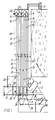
- the heat exchanger illustrated in the drawings includes a central furnace chamber l defined by a shell, which comprises an upper, cylindric part 2, a conical bottom part 3 and a top cover 4.
- a fuel burner (not shown) is mounted in a central tubular member 5 of reduced diameter, extending upwardly from top cover 4.
- a plurality of outlet tubes 6 for combustion gases produced in furnace chamber l extend outwardly from the conical bottom part 3, and each tube 6 opens into a plenum or turning chamber 7 from which a plurality of smoke tubes 8 extend vertically upward.
- the smoke tubes are distributed along a pitch circle concentric with the shell of furnace chamber l, and at their upper ends they open into one or more plenum chambers 9, from which another plurality of smoke tubes l0 extend downwardly along a circle concentric with the pitch circle of smoke tubes 8.
- Each smoke tube l0 opens into a lower plenum chamber ll concentric with plenum chamber 7 and separated therefrom by a vertical partition wall. As illustrated in Fig.
- the heat exchanger comprises two further, circular rows of smoke tubes l2 and l3, respectively, which conduct the combustion gases from each plenum chamber ll via an upper plenum chamber l4 concentric with chamber 9 to a lower plenum chamber l5 from which the combustion gases are discharged through an outlet (not shown).
- a plurality of series-connected air flow passages l6, l7, l8, and l9, each of which surrounds a respective group of smoke tubes, is defined between a succession of vertical walls 20, 2l, 22, 23, and 24, all coaxial with the shell 2 of furnace chamber l.
- the air passages are interconnected through alternate upper and lower plenum or turning chambers 25, 26, and 27. Air to be heated flows through an inlet (not shown) to a distributor chamber 28 into which the lower ends of air passages l6 open, and the heated air is discharged from the heat exchanger through a collector chamber 29 into which the lower ends of air passages l9 open.
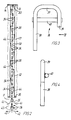
- Fig. 2 is a vertical section through one of the smoke tubes l2 which at its ends is sealingly secured in the top wall 30 of plenum chamber ll and the bottom wall 3l of plenum chamber l4, respectively.
- heat from the upwardly flowing combustion gases is to be transferred to the air flowing downwardly through the surrounding air passage l7.
- a chain generally designated by 32, is suspended centrally within each of the total number of smoke tubes in the heat exchanger.
- Each chain 32 extends throughout the height of the associated tube from a supporting pin 33 welded to the tube adjacent its upper end down to a level below the top wall 30 of the lower plenum chamber ll.
- chain 32 is composed of successive groups of relatively larger and smaller chain links designated by 34 and 35, respectively.
- transverse dimension or width of chain links 34 may be approximately one third of the inner tube diameter, and the width of links 35 may be correspondingly smaller, as shown. It is preferred that the portion of chain 32, which protrudes below wall 30 into chamber ll, is composed of the smaller links 35.
- a deflector or twister element 36 which is shown on a considerably larger scale in Figs. 3 and 4.
- Deflector element 36 is U-shaped with a horizontal upper limb 37 and two parallel vertical limbs 38 and 39 of which limb 38 is substantially longer than limb 39.
- a crossbar 40 is welded to the vertical limbs 38 and 39 on one side of the deflector element so as to create an "unbalanced" mass distribution of the element in the sense that its centre of mass will be offset, both in the general plane of the element and at right angles thereto, relative to the longitudinal axis of chain 32 when deflector element 36 is welded thereto at the center of its upper limb 37, as shown in Fig. 2.
Landscapes
- Engineering & Computer Science (AREA)
- Mechanical Engineering (AREA)
- General Engineering & Computer Science (AREA)
- Chemical & Material Sciences (AREA)
- Combustion & Propulsion (AREA)
- Physics & Mathematics (AREA)
- Thermal Sciences (AREA)
- Heat-Exchange Devices With Radiators And Conduit Assemblies (AREA)
Applications Claiming Priority (2)
| Application Number | Priority Date | Filing Date | Title |
|---|---|---|---|
| DK4563/85 | 1985-10-07 | ||
| DK456385A DK456385A (da) | 1985-10-07 | 1985-10-07 | Udstyr til at forebygge aflejringer paa vertikale varmevekslervaegge |
Publications (1)
| Publication Number | Publication Date |
|---|---|
| EP0219986A1 true EP0219986A1 (en) | 1987-04-29 |
Family
ID=8134691
Family Applications (1)
| Application Number | Title | Priority Date | Filing Date |
|---|---|---|---|
| EP86307355A Withdrawn EP0219986A1 (en) | 1985-10-07 | 1986-09-25 | Apparatus for preventing the formation of deposits on vertical heat exchanger walls |
Country Status (2)
| Country | Link |
|---|---|
| EP (1) | EP0219986A1 (da) |
| DK (1) | DK456385A (da) |
Cited By (1)
| Publication number | Priority date | Publication date | Assignee | Title |
|---|---|---|---|---|
| CN113819483A (zh) * | 2021-09-18 | 2021-12-21 | 华能曲阜热电有限公司 | 一种减缓积灰耐腐蚀的空预器 |
Citations (6)
| Publication number | Priority date | Publication date | Assignee | Title |
|---|---|---|---|---|
| DE457572C (de) * | 1928-03-20 | Paul Cimbolek | Selbsttaetiger Rohrreiniger fuer Kondensatorrohre | |
| FR1027888A (fr) * | 1949-11-24 | 1953-05-18 | Rekuperator K G | Dispositif permettant d'augmenter la transmission de chaleur dans les échangeurs de température, ainsi que les échangeurs munis de ce dispositif |
| DE1003905B (de) * | 1953-08-25 | 1957-03-07 | Rudolf Hingst Dipl Ing | Vorrichtung zur rauchgasseitigen Reinigung der Rohre von Waermeaustauschern mittels Ketten |
| CH505360A (de) * | 1969-03-27 | 1971-03-31 | Ygnis Sa | Turbulenzerhöhender Einsatz für Wärmeaustauscher und dessen Verwendung in Rauchgaskanälen |
| GB2124322A (en) * | 1982-07-20 | 1984-02-15 | Holden William J | Heat exchanger cleaner |
| DE3327321A1 (de) * | 1983-07-29 | 1985-02-07 | Motoren-Werke Mannheim AG vorm. Benz Abt. stationärer Motorenbau, 6800 Mannheim | Vorrichtung zum reinigen des mindestens einen rohres von waermeuebertragern |
-
1985
- 1985-10-07 DK DK456385A patent/DK456385A/da not_active Application Discontinuation
-
1986
- 1986-09-25 EP EP86307355A patent/EP0219986A1/en not_active Withdrawn
Patent Citations (6)
| Publication number | Priority date | Publication date | Assignee | Title |
|---|---|---|---|---|
| DE457572C (de) * | 1928-03-20 | Paul Cimbolek | Selbsttaetiger Rohrreiniger fuer Kondensatorrohre | |
| FR1027888A (fr) * | 1949-11-24 | 1953-05-18 | Rekuperator K G | Dispositif permettant d'augmenter la transmission de chaleur dans les échangeurs de température, ainsi que les échangeurs munis de ce dispositif |
| DE1003905B (de) * | 1953-08-25 | 1957-03-07 | Rudolf Hingst Dipl Ing | Vorrichtung zur rauchgasseitigen Reinigung der Rohre von Waermeaustauschern mittels Ketten |
| CH505360A (de) * | 1969-03-27 | 1971-03-31 | Ygnis Sa | Turbulenzerhöhender Einsatz für Wärmeaustauscher und dessen Verwendung in Rauchgaskanälen |
| GB2124322A (en) * | 1982-07-20 | 1984-02-15 | Holden William J | Heat exchanger cleaner |
| DE3327321A1 (de) * | 1983-07-29 | 1985-02-07 | Motoren-Werke Mannheim AG vorm. Benz Abt. stationärer Motorenbau, 6800 Mannheim | Vorrichtung zum reinigen des mindestens einen rohres von waermeuebertragern |
Cited By (1)
| Publication number | Priority date | Publication date | Assignee | Title |
|---|---|---|---|---|
| CN113819483A (zh) * | 2021-09-18 | 2021-12-21 | 华能曲阜热电有限公司 | 一种减缓积灰耐腐蚀的空预器 |
Also Published As
| Publication number | Publication date |
|---|---|
| DK456385D0 (da) | 1985-10-07 |
| DK456385A (da) | 1987-04-08 |
Similar Documents
| Publication | Publication Date | Title |
|---|---|---|
| KR840004563A (ko) | 원 드럼 보일러 시스템 | |
| US20050061261A1 (en) | Coal-fired power station | |
| US5799622A (en) | Furnace heat exchanger tube cleaning system | |
| EP1461567B1 (en) | Steam super heater comprising shield pipes | |
| NL8102569A (nl) | Waterverwarmingsinrichting. | |
| US5558046A (en) | Fire-tube boiler | |
| EP0219986A1 (en) | Apparatus for preventing the formation of deposits on vertical heat exchanger walls | |
| US2246349A (en) | Fly ash trap | |
| RU92004418A (ru) | Водотрубный котел | |
| US4471725A (en) | Heat exchanger cleaner | |
| EP0251247B1 (en) | Power plant with combustion of a fuel in a fluidized bed | |
| US2591398A (en) | Fire tube furnace with flue gas turbulator | |
| GB2124322A (en) | Heat exchanger cleaner | |
| US190743A (en) | Improvement in circulating devices for steam-boilers | |
| CN213207912U (zh) | 一种燃煤锅炉省煤器后烟道旋流除灰混流装置 | |
| JP2017150790A (ja) | 排気ダクト及びボイラ並びに固体粒子の除去方法 | |
| US4627387A (en) | Fluidized-bed apparatus with a heat exchanger and an additional-air blowing network | |
| NL8401607A (nl) | Inrichting voor het reinigen van een warmtewisselaar. | |
| RU2743913C2 (ru) | Жалюзийный щелевой золоуловитель | |
| SU1316585A1 (ru) | Зерноуборочна машина "Суховей-пульсар | |
| CA2209148C (en) | Furnace heat exchanger tube cleaning system | |
| SU1674910A1 (ru) | Пылеуловитель лабиринтного типа | |
| SU997824A1 (ru) | Батарейный циклон-теплообменник | |
| JPH0245624Y2 (da) | ||
| CN212456910U (zh) | 一种自除尘省煤器 |
Legal Events
| Date | Code | Title | Description |
|---|---|---|---|
| PUAI | Public reference made under article 153(3) epc to a published international application that has entered the european phase |
Free format text: ORIGINAL CODE: 0009012 |
|
| AK | Designated contracting states |
Kind code of ref document: A1 Designated state(s): BE DE FR GB SE |
|
| STAA | Information on the status of an ep patent application or granted ep patent |
Free format text: STATUS: THE APPLICATION IS DEEMED TO BE WITHDRAWN |
|
| 18D | Application deemed to be withdrawn |
Effective date: 19871030 |
|
| ITF | It: translation for a ep patent filed | ||
| RIN1 | Information on inventor provided before grant (corrected) |
Inventor name: KOLLERUP, VAGN Inventor name: JADOUIN, MICHEL ALBERT |