EP0219954A1 - Infrarot-Detektorsystem - Google Patents
Infrarot-Detektorsystem Download PDFInfo
- Publication number
- EP0219954A1 EP0219954A1 EP86306815A EP86306815A EP0219954A1 EP 0219954 A1 EP0219954 A1 EP 0219954A1 EP 86306815 A EP86306815 A EP 86306815A EP 86306815 A EP86306815 A EP 86306815A EP 0219954 A1 EP0219954 A1 EP 0219954A1
- Authority
- EP
- European Patent Office
- Prior art keywords
- infra
- lens
- sensor
- view
- red
- Prior art date
- Legal status (The legal status is an assumption and is not a legal conclusion. Google has not performed a legal analysis and makes no representation as to the accuracy of the status listed.)
- Withdrawn
Links
- 230000003287 optical effect Effects 0.000 claims abstract description 13
- 238000001514 detection method Methods 0.000 claims abstract description 7
- 238000010586 diagram Methods 0.000 description 4
- 230000033001 locomotion Effects 0.000 description 3
- 239000000463 material Substances 0.000 description 3
- 238000000034 method Methods 0.000 description 3
- 239000004698 Polyethylene Substances 0.000 description 2
- 230000005540 biological transmission Effects 0.000 description 2
- -1 polyethylene Polymers 0.000 description 2
- 229920000573 polyethylene Polymers 0.000 description 2
- 230000003321 amplification Effects 0.000 description 1
- 238000005452 bending Methods 0.000 description 1
- 238000010276 construction Methods 0.000 description 1
- 230000000694 effects Effects 0.000 description 1
- 229910052732 germanium Inorganic materials 0.000 description 1
- GNPVGFCGXDBREM-UHFFFAOYSA-N germanium atom Chemical compound [Ge] GNPVGFCGXDBREM-UHFFFAOYSA-N 0.000 description 1
- 238000003199 nucleic acid amplification method Methods 0.000 description 1
- 239000004033 plastic Substances 0.000 description 1
- 229920003023 plastic Polymers 0.000 description 1
- 239000002985 plastic film Substances 0.000 description 1
- 230000004304 visual acuity Effects 0.000 description 1
Images


Classifications
-
- G—PHYSICS
- G08—SIGNALLING
- G08B—SIGNALLING OR CALLING SYSTEMS; ORDER TELEGRAPHS; ALARM SYSTEMS
- G08B13/00—Burglar, theft or intruder alarms
- G08B13/18—Actuation by interference with heat, light, or radiation of shorter wavelength; Actuation by intruding sources of heat, light, or radiation of shorter wavelength
- G08B13/189—Actuation by interference with heat, light, or radiation of shorter wavelength; Actuation by intruding sources of heat, light, or radiation of shorter wavelength using passive radiation detection systems
- G08B13/19—Actuation by interference with heat, light, or radiation of shorter wavelength; Actuation by intruding sources of heat, light, or radiation of shorter wavelength using passive radiation detection systems using infrared-radiation detection systems
- G08B13/193—Actuation by interference with heat, light, or radiation of shorter wavelength; Actuation by intruding sources of heat, light, or radiation of shorter wavelength using passive radiation detection systems using infrared-radiation detection systems using focusing means
Definitions
- the invention relates to a motion detection system mainly used as an intruder sensor in burglar alarm systems.
- the invention herein described detects changes in infra- red (7-12 micron wavelength) energy collected by a plurality of optical fields-of-view, each focussing on a common infra-red sensing device such that when an intruder moves across the field-of-view the instantaneous infra-red energy level falling on the detector will fluctuate and thus provide a fluctuating electrical signal.
- intruder detectors using these techniques have been in use in the security industry for many years.
- the means of achieving a plurality of fields-of-view in currently available intruder sensors fall broadly into two types.
- One type uses a number of reflective elements such as spherical, parabolic or other conic-section mirrors or mirror segments, located radially around a common infra-red detector such that the detector is at the focus of each mirror.
- the axis of each mirror is arranged to radiate from the unit radially so that the room or area to be protected is covered by a fan shaped series of fields-of-view. It is common practice to have a further series of mirror segments similarly sharing the common detector, but arranged to provide a further fan-shaped array of fields of view angled below the first set to prevent an intruder moving below then and thus avoiding detection.
- the other common type of intruder sensor uses a plurality of refractive elements, typically an array of Fresnel lenses, sharing an infra-red detector located at the common focus of the lenses, which are radially disposed to provide a fan-shaped series of fields of view. Again, further ranks of lenses may be used to provide additional downward-pointing fields of view to prevent an intruder avoiding detection.
- refractive elements typically an array of Fresnel lenses, sharing an infra-red detector located at the common focus of the lenses, which are radially disposed to provide a fan-shaped series of fields of view.
- further ranks of lenses may be used to provide additional downward-pointing fields of view to prevent an intruder avoiding detection.
- the infra-red detecting device is typically a commercially available pyro-electric device having two sensing elements electrically connected in opposition, such that changes in infra-red energy falling upon both detectors simultaneously will cause cancellation of signals, whereas energy falling on one or other element will cause an electrical output.
- the infra-red detecting device is typically a commercially available pyro-electric device having two sensing elements electrically connected in opposition, such that changes in infra-red energy falling upon both detectors simultaneously will cause cancellation of signals, whereas energy falling on one or other element will cause an electrical output.
- both detector elements are located on the focal plane of the focussing mirrors or lenses, each mirror or lens axis provides in effect two fields of view, one for each element.
- each lens segment should be flat, with the bending only occurring at the gaps between the segments, in practice the lens segments take on the general curvature of the array, and thus cause considerable abberation and loss of focus of the intruder's infra-red energy falling upon the detector.
- the present invention seeks to overcome the disadvantages shown above by providing a means wherein a plurality of fields of view . are obtained without the need for a plurality of mirror or lens segments thus giving a considerable space saving in the vulnerable frontal area of a complete intruder sensor.
- United Kingdom Patent No. 1 3?5 410 describes an intruder alarm using a concave mirror divided into separate segments. Such an arrangement can only achieve a good resolving power if the mirror segments have a long focal length and large individual dimensions, for the reasons described above. Furthermore, such an arrangement has a large number of components which require to be accurately positioned, and leads to a complicated and expensive construction.
- the arrangement of the present invention in contrast, is simpler, cheaper and easier to construct and adjust.
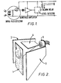
- the circuit of Figure 1 shows an infra-red sensor comprising two detectors connected back to back in the input circuit of a band pass amplifier. The output of this amplifier is applied to a threshhold device and when the signal level exceeds the threshhold, an alarm relay is activated.
- FIG. 2 is an exploded view of the optical components of the invention.
- a Fresnel lens plate 1 is focussed on the surface of an infra-red sensor 5, the sensor 5 has two detecting elements connected in opposition behind a filter window which allows transmission of infra-red energy of more than 6 microns wavelength.
- a pair of vertical mirrors 2 and 3 inclined at a small angle preferably about 6 degrees, to the optic axis of the Fresnel lens plate 1.
- a further reflector 4 inclined to the horizontal similarly at a small angle.
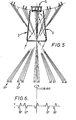
- Figure 3 shows diagrammatically in plan view some of the fields of view generated by this arrangement. As shown in Figure 3, five diverging fields of view are generated, only three of which are shown in the diagram for clarity.
- a first field of view indicated by dashed lines with single arrows corresponds to an infra-red beam falling normally onto the surface of the lens plate 1 and focussed by it onto the detector 5.
- a second field of view indicated by the dashed lines with double arrows corresponds to a beam focussed by the lens 1 and reflected by the mirror surface 2 onto the detector 5.
- a similar field of view not shown in the diagram correspond to a beam symmetrically disposed on the other side of the axis and reflected by the mirror 3.
- a further field corresponds to a beam indicated by the triple headed arrows which after refraction by the lens 1 is reflected twice, once at the mirror 3 and a second time at the mirror 2 before reaching the detector 5.
- a similar field not shown in the diagram exists on the other side of the axis corresponding to reflection first at the mirror 2 and then at the mirror 3.
- Figure 4 is a diagrammatic sectional elevation showing how the top mirror 4 provides a lower set of fields of view corresponding to those in Figure 3.
- the dashed lines with single arrow heads correspond to the upper fields while those with double arrow heads show fields corresponding to reflection by the mirror 4 and inclined downwards in order to detect an intruder below the main fields.
- Figure 5 shows how the apparent images of the detector caused by reflectors 2 and 3 determine the positions of the fields of view.
- Figure 6 shows a typical electrical signal resulting from an intruder crossing through all fields of view.
- the positive-going signals result from detector element A receiving energy, and the negative-going signal results from detector element B receiving energy.
- the relative spacing and angles of the plane reflectors may be changed to give different positions of the fields of view.
- Infra-red energy may enter the system from angles wider than those shown by means of further internal reflections D etween reflectors 2 and 3 before finally reaching the detecting elements.
- this energy will be unfocussed, due to the excessive path length, and also may arrive at the detector front filter window at or above the angle of incidence or cone of acceptance.
- the detector 5 is located closer to the lens than the ideal focal length, and the resulting loss of focus compensated for by a lower f number than would be required for an ideally placed detector.
- energy arriving at the detector via one or both plane reflectors 2 and 3 will be in focus and all arrive at the detecting element, thereby compensating for reflective losses.
- plane reflector 4 ensures that energy arriving from locations vertically below fields of view, Al, B1 to A5, B5, and within the lower angled fields of view, will arrive at the detector elements A or B.
- Figure 4 shows the path by which energy from an intruder entering angled fields of view A6 would reach detector element A via plane reflector 4.
- energy entering the other angled fields of view would arrive via reflectors 2 or 3 and 4.
- an intruder sensor would preferably be located about 7ft. (2.1 metres) above the floor and angled such that the main rank of fields of view would be angled at about 10° downwards.
- the lower angled fields of view angled at about 40° downwards would therefore reach the floor at a distance of some 12 feet (3.6 metres).
- the de-focussed and therefore wider field of view would still gather sufficient energy from the relatively close intruder. Note: (provided the intruder full fills the field of view, the energy collected will remain constant with his distance from the sensor).
- two positive focus lenses A and B are located in relation to two plane reflectors.
- the lenses are off-axis segments.
- Figure 8 shows the electrical signal from detector 5 for movement of an intruder across the fields of view.
- a further embodiment, shown in Figure 9, shows the axis for lens A going through the lens segment, whereas the axis for lens B is outside the lens segment.
- This arrangement may also provide means whereby the fields of view may be interleaved or interspaced.
- Fresnel type lenses but normal refractive lenses made from germanium, or other material offering a low loss to 7 - 12 micron infra-red energy, may also be used.
Landscapes
- Physics & Mathematics (AREA)
- General Physics & Mathematics (AREA)
- Burglar Alarm Systems (AREA)
- Geophysics And Detection Of Objects (AREA)
Applications Claiming Priority (2)
| Application Number | Priority Date | Filing Date | Title |
|---|---|---|---|
| GB858522086A GB8522086D0 (en) | 1985-09-05 | 1985-09-05 | Infra-red detector system |
| GB8522086 | 1985-09-05 |
Publications (1)
| Publication Number | Publication Date |
|---|---|
| EP0219954A1 true EP0219954A1 (de) | 1987-04-29 |
Family
ID=10584784
Family Applications (1)
| Application Number | Title | Priority Date | Filing Date |
|---|---|---|---|
| EP86306815A Withdrawn EP0219954A1 (de) | 1985-09-05 | 1986-09-03 | Infrarot-Detektorsystem |
Country Status (2)
| Country | Link |
|---|---|
| EP (1) | EP0219954A1 (de) |
| GB (1) | GB8522086D0 (de) |
Cited By (9)
| Publication number | Priority date | Publication date | Assignee | Title |
|---|---|---|---|---|
| GB2199659A (en) * | 1986-12-01 | 1988-07-13 | Floorplan Electrica Ltd | Occupancy sensing device |
| GB2213927A (en) * | 1987-12-18 | 1989-08-23 | Philips Electronic Associated | Pyroelectric infrared sensors |
| GB2221984A (en) * | 1988-05-11 | 1990-02-21 | Graham Wild | Optical detector |
| EP0435120A3 (en) * | 1989-12-23 | 1992-06-17 | Asea Brown Boveri Aktiengesellschaft | Passive infra-red movement detector |
| DE4218151A1 (de) * | 1991-06-03 | 1992-12-10 | Murata Manufacturing Co | System und verfahren zum erfassen einer waermequellenbewegung |
| EP0537024A1 (de) * | 1991-10-10 | 1993-04-14 | Security Enclosures Limited | Infrarote-Detektierungsvorrichtung |
| US5414255A (en) * | 1993-11-08 | 1995-05-09 | Scantronic Limited | Intrusion detector having a generally planar fresnel lens provided on a planar mirror surface |
| GB2286042A (en) * | 1994-01-27 | 1995-08-02 | Security Enclosures Ltd | Wide angle passive infra-red intruder detector |
| DE4430778A1 (de) * | 1994-08-30 | 1996-03-07 | Sick Optik Elektronik Erwin | Tubus |
Citations (7)
| Publication number | Priority date | Publication date | Assignee | Title |
|---|---|---|---|---|
| US3703718A (en) * | 1971-01-07 | 1972-11-21 | Optical Coating Laboratory Inc | Infrared intrusion detector system |
| US4087688A (en) * | 1976-06-16 | 1978-05-02 | Cerberus Ag | Infrared radiation-burglary detector |
| DE2836462A1 (de) * | 1978-08-21 | 1980-03-06 | Woerl Alarm August Woerl Inhab | Raumueberwachungs-empfangseinrichtung |
| EP0065159A2 (de) * | 1981-05-18 | 1982-11-24 | Richard Hirschmann Radiotechnisches Werk | Bewegungsmelder zur Raumüberwachung |
| US4442359A (en) * | 1982-03-01 | 1984-04-10 | Detection Systems, Inc. | Multiple field-of-view optical system |
| DE3424135A1 (de) * | 1984-06-30 | 1986-01-09 | Richard Hirschmann Radiotechnisches Werk, 7300 Esslingen | Meldeeinrichtung zur raumueberwachung |
| EP0177130B1 (de) * | 1984-09-25 | 1989-03-08 | Matsushita Electric Works, Ltd. | Passiver Infrarotstrahlungsdetektor |
-
1985
- 1985-09-05 GB GB858522086A patent/GB8522086D0/en active Pending
-
1986
- 1986-09-03 EP EP86306815A patent/EP0219954A1/de not_active Withdrawn
Patent Citations (8)
| Publication number | Priority date | Publication date | Assignee | Title |
|---|---|---|---|---|
| US3703718A (en) * | 1971-01-07 | 1972-11-21 | Optical Coating Laboratory Inc | Infrared intrusion detector system |
| US3703718B1 (de) * | 1971-01-07 | 1982-04-13 | ||
| US4087688A (en) * | 1976-06-16 | 1978-05-02 | Cerberus Ag | Infrared radiation-burglary detector |
| DE2836462A1 (de) * | 1978-08-21 | 1980-03-06 | Woerl Alarm August Woerl Inhab | Raumueberwachungs-empfangseinrichtung |
| EP0065159A2 (de) * | 1981-05-18 | 1982-11-24 | Richard Hirschmann Radiotechnisches Werk | Bewegungsmelder zur Raumüberwachung |
| US4442359A (en) * | 1982-03-01 | 1984-04-10 | Detection Systems, Inc. | Multiple field-of-view optical system |
| DE3424135A1 (de) * | 1984-06-30 | 1986-01-09 | Richard Hirschmann Radiotechnisches Werk, 7300 Esslingen | Meldeeinrichtung zur raumueberwachung |
| EP0177130B1 (de) * | 1984-09-25 | 1989-03-08 | Matsushita Electric Works, Ltd. | Passiver Infrarotstrahlungsdetektor |
Cited By (16)
| Publication number | Priority date | Publication date | Assignee | Title |
|---|---|---|---|---|
| GB2199659B (en) * | 1986-12-01 | 1991-08-14 | Floorplan Electrica Ltd | Occupancy detectors etc |
| GB2199659A (en) * | 1986-12-01 | 1988-07-13 | Floorplan Electrica Ltd | Occupancy sensing device |
| GB2213927A (en) * | 1987-12-18 | 1989-08-23 | Philips Electronic Associated | Pyroelectric infrared sensors |
| EP0321051A3 (de) * | 1987-12-18 | 1990-05-23 | Philips Electronics Uk Limited | Pyroelektrische Infrarotsensoren |
| GB2221984A (en) * | 1988-05-11 | 1990-02-21 | Graham Wild | Optical detector |
| EP0435120A3 (en) * | 1989-12-23 | 1992-06-17 | Asea Brown Boveri Aktiengesellschaft | Passive infra-red movement detector |
| DE4218151C2 (de) * | 1991-06-03 | 2003-05-28 | Murata Manufacturing Co | System zum Erfassen der Bewegung einer Wärmequelle |
| DE4218151A1 (de) * | 1991-06-03 | 1992-12-10 | Murata Manufacturing Co | System und verfahren zum erfassen einer waermequellenbewegung |
| EP0537024A1 (de) * | 1991-10-10 | 1993-04-14 | Security Enclosures Limited | Infrarote-Detektierungsvorrichtung |
| US5414255A (en) * | 1993-11-08 | 1995-05-09 | Scantronic Limited | Intrusion detector having a generally planar fresnel lens provided on a planar mirror surface |
| US5572033A (en) * | 1994-01-27 | 1996-11-05 | Security Enclosures Limited | Wide-angle infra-red detection apparatus |
| GB2286042B (en) * | 1994-01-27 | 1998-07-29 | Security Enclosures Ltd | Wide-angle infra-red detection apparatus |
| GB2286042A (en) * | 1994-01-27 | 1995-08-02 | Security Enclosures Ltd | Wide angle passive infra-red intruder detector |
| DE4430778A1 (de) * | 1994-08-30 | 1996-03-07 | Sick Optik Elektronik Erwin | Tubus |
| US5748816A (en) * | 1994-08-30 | 1998-05-05 | Sick Ag | Optical cavity for exclusively receiving light parallel to an optical axis |
| DE4430778C2 (de) * | 1994-08-30 | 2000-01-27 | Sick Ag | Tubus |
Also Published As
| Publication number | Publication date |
|---|---|
| GB8522086D0 (en) | 1985-10-09 |
Similar Documents
| Publication | Publication Date | Title |
|---|---|---|
| US4930864A (en) | Domed segmented lens systems | |
| US4523095A (en) | Radiation detector with asymmetrical pattern | |
| US4442359A (en) | Multiple field-of-view optical system | |
| US4734585A (en) | Passive infra-red sensor | |
| CA1175525A (en) | Passive infrared intrusion detection system | |
| US4321594A (en) | Passive infrared detector | |
| US6211522B1 (en) | Passive infra-red intrusion sensor | |
| US4429224A (en) | Optical arrangement for an infrared intrusion detector | |
| US4841284A (en) | Infrared intrusion detection system incorporating a fresnel lens and a mirror | |
| US4342987A (en) | Intruder detection system | |
| US5572033A (en) | Wide-angle infra-red detection apparatus | |
| US5308985A (en) | Wide-angle passive infrared radiation detector | |
| US6239437B1 (en) | Passive infrared detector | |
| US4318089A (en) | Infrared detector system | |
| US3886360A (en) | Infrared intrusion detection apparatus | |
| US4058726A (en) | Radiation detector | |
| US4709152A (en) | Infrared intrusion detector | |
| WO1988004038A1 (en) | Motion detector | |
| JPH023150B2 (de) | ||
| US4238675A (en) | Optics for infrared intrusion detector | |
| EP0219954A1 (de) | Infrarot-Detektorsystem | |
| US5818337A (en) | Masked passive infrared intrusion detection device and method of operation therefore | |
| US4535240A (en) | Intruder detection | |
| US5124546A (en) | Method and apparatus for refracting light to an optical detector | |
| US4429223A (en) | Infrared intrusion detector |
Legal Events
| Date | Code | Title | Description |
|---|---|---|---|
| PUAI | Public reference made under article 153(3) epc to a published international application that has entered the european phase |
Free format text: ORIGINAL CODE: 0009012 |
|
| AK | Designated contracting states |
Kind code of ref document: A1 Designated state(s): AT BE CH DE FR GB IT LI LU NL SE |
|
| 17P | Request for examination filed |
Effective date: 19871021 |
|
| STAA | Information on the status of an ep patent application or granted ep patent |
Free format text: STATUS: THE APPLICATION IS DEEMED TO BE WITHDRAWN |
|
| 18D | Application deemed to be withdrawn |
Effective date: 19890331 |
|
| RIN1 | Information on inventor provided before grant (corrected) |
Inventor name: GRANT, JOHN T. |