EP0219888A2 - Abschlusssystem - Google Patents
Abschlusssystem Download PDFInfo
- Publication number
- EP0219888A2 EP0219888A2 EP86200826A EP86200826A EP0219888A2 EP 0219888 A2 EP0219888 A2 EP 0219888A2 EP 86200826 A EP86200826 A EP 86200826A EP 86200826 A EP86200826 A EP 86200826A EP 0219888 A2 EP0219888 A2 EP 0219888A2
- Authority
- EP
- European Patent Office
- Prior art keywords
- closure
- doorway
- bracket
- wheel
- floor
- Prior art date
- Legal status (The legal status is an assumption and is not a legal conclusion. Google has not performed a legal analysis and makes no representation as to the accuracy of the status listed.)
- Granted
Links
Images
Classifications
-
- B—PERFORMING OPERATIONS; TRANSPORTING
- B64—AIRCRAFT; AVIATION; COSMONAUTICS
- B64C—AEROPLANES; HELICOPTERS
- B64C1/00—Fuselages; Constructional features common to fuselages, wings, stabilising surfaces or the like
- B64C1/14—Windows; Doors; Hatch covers or access panels; Surrounding frame structures; Canopies; Windscreens accessories therefor, e.g. pressure sensors, water deflectors, hinges, seals, handles, latches, windscreen wipers
- B64C1/1407—Doors; surrounding frames
- B64C1/1415—Cargo doors, e.g. incorporating ramps
-
- B—PERFORMING OPERATIONS; TRANSPORTING
- B64—AIRCRAFT; AVIATION; COSMONAUTICS
- B64C—AEROPLANES; HELICOPTERS
- B64C1/00—Fuselages; Constructional features common to fuselages, wings, stabilising surfaces or the like
- B64C1/14—Windows; Doors; Hatch covers or access panels; Surrounding frame structures; Canopies; Windscreens accessories therefor, e.g. pressure sensors, water deflectors, hinges, seals, handles, latches, windscreen wipers
- B64C1/1407—Doors; surrounding frames
Definitions
- the most important application of my invention involves an aircraft door which can be opened during flight and then moved to a location remote from the doorway it is provided to block to facilitate the deployment of equipment, parachutists, etc., through the doorway.
- Aircraft doors which can be opened during flight have been proposed.
- One such proposal involves a track-mounted inwardly opening door.
- This arrangement has the decided disadvantage that the track mechanism takes up considerable valuable space in the interior of the aircraft.
- the track mechanism also impedes movement of men and material in its vicinity.
- the door is quickly and simply removed for transfer to an out-of-the-way location by opening the catch at the upper end of the door and rotating the door inwardly about horizontally extending, door-carried lugs seated in the door-supporting bracket until the roller is lowered into engagement with the floor of the aircraft.
- the lugs by which it is supported upwardly and out of recesses in the bracket in which they are seated, allowing the operator to roll the door away to, and stow it in, an appropriate out-of-the-way location.
- Latches incorporated in the door-supporting bracket are then released, allowing the latter to be removed and stowed away to provide a clear pathway to the aircraft's doorway.
- the brack may be used to secure in place the lower end of the door also removed to that location for storage.
- this novel closure system simply and inexpensively solves the problem of furnishing access through the doorway of a high-speed aircraft during flight. This is accomplished in a manner which does not require that permanently mounted tracks, brackets, or other components be located in the aircraft's interior, and a clear pathway to the aircraft's doorway is provided when the door is removed. Furthermore, the door can be easily removed, stowed, and returned to its doorway blocking position by a single person.
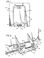
- figure 1 depicts the fuselage 20 of a high-speed aircraft. That fuselage has a doorway 22 which can be closed or blocked by the plug-fitting door 24 of a closure system constructed in accord with, and embodying, the principles of the present invention and identified by reference character 26.
- closure system 26 Aside from door 24, the major components of closure system 26 include a catch mechanism 28 for latching the upper end of door 24 to the fuselage 20 of the aircraft, a wheel 30 which makes door 24 mobile and allows it to be rolled to an out-of-the-way storage location by a single person, and a door-supporting bracket 32 removably latched to the floor 34 of the aircraft. This bracket supports the lower end of door 24 from the floor of the aircraft in the illustrated position in which that door blocks doorway 22.
- the illustrated upper catch 28 is the one conventionally employed on the doors of a Boeing 737 twinjet. For this reason that component of closure system 26 will not be disclosed herein.
- the other components of the closure system, except for the door iself (which can be of any desired construction), are described below.
- FIG. 2 two parallel, spaced apart wheel supports 36 and 38 are bolted or otherwise attached to door 24 at the lower end 40 thereof.
- Journalled in supports 36 and 38 is a horizontally extending axle 42 for wheel 30.
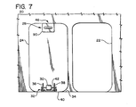
- Door 24 can be rolled on this wheel between the doorway obstructing or blocking position shown in FIG. 1 to the out-of-the-way storage position shown in FIG. 7 and identified by reference character 46.
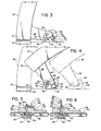
- the detachable, floor-mounted, bracket 32 has a platform 48 with vertically extending stanchions 50 and 52 at the opposite ends thereof.
- upwardly extending, inwardly opening recesses 54 are formed in stanchions 50 and 52. These recesses are configured to provide seats for horizontally extending, door supporting, lugs 56 (only one shown). These lugs are fixed to the door mounted, wheel-supporting brackets 36 and 38 and extend in opposite directions from those supports along a horizontal axis parallel to, but spaced from, the horizontal axis of rotation of wheel-supporting axle 42.
- a bracket retaining track 58 is mounted in the floor 34 of the aircraft parallel to vertically extending fuselage wall 60.
- track 58 has an upwardly opening, C-Sectioned channel 60 surmounted by a keeper which is flat, horizontally oriented keyway 62.
- the track is mounted immediately subjacent the floor 34 of the aircraft and is reachable through an elongated slot 64 in that floor.
- Openings 66 of relatively larger diameter are altemated with slotted detents 68 in the keyway 62 of track 58.
- Aircraft of the type for which the closure systems disclosed herein are particularly designed will typically have a track of the character and orientation just described as original equipment.
- the illustrated arrangement for example, is that utilized by Boeing Commercial Aircraft Company to lock passenger seats in place.
- door-supporting bracket 32 also includes two identical latching mechanisms 70 and 72 for detachably coupling the bracket to the floor-mounted track 58 just described.
- Stem 74 is mounted for up-and-down, vertical sliding movement in a horizontal ledge 80 which is integral with, and extends toward the center of bracket platform 48 from, the stanchion 50 at the end of bracket 32.
- Retainer 78 is integral with the lower end of stem 74 and is dimensioned so that it can move freely upward through keyway 62 of track 58 when it is positioned opposite one of the enlarged openings 66 through the keyway but will be trapped below and against a keyway detent 68 when it is located opposite one of those detents 68.
- Latch actuator 76 includes a lever 82 fixed by a pivot pin 84 to the upper end of stem 74. Formed at that end of lever 82 is a downwardly extending cam 86. That cam is engageable with the upper surface 88 of ledge 80 to displace stem 74 upwardly and clamp retainer 78 against the lower side of keyway 62, thereby securely fixing bracket 32 to track 58 when lever 82 is rotated in a clockwise direction from the "unlatch" position shown in FIG. 6 to the "latch" position of FIG. 5.
- the first step in removing door 24 to permit movement through doorway 22 is to raise handle 90 of catch mechanism 28. This releases catches (not shown) which engage the door casing. Door 24 can subsequently be pulled inwardly and downwardly into the aircraft's interior.
- Raising handle 90 also equalizes the pressure in the aircraft fuselage with the ambient pressure through an also conventional port so that artifacts in the aircraft and/or persons therein will not be thrown about the compartment or blown out through the doorway when door 24 is opened.
- door 24 is rolled on wheel 30 to an out-of-the-way storage position such as that mentioned above and identified by reference character 46 in FIG. 7.
Landscapes
- Engineering & Computer Science (AREA)
- Mechanical Engineering (AREA)
- Aviation & Aerospace Engineering (AREA)
- Support Devices For Sliding Doors (AREA)
- Power-Operated Mechanisms For Wings (AREA)
- Vending Machines For Individual Products (AREA)
Applications Claiming Priority (2)
| Application Number | Priority Date | Filing Date | Title |
|---|---|---|---|
| US789499 | 1985-10-21 | ||
| US06/789,499 US4787577A (en) | 1985-10-21 | 1985-10-21 | Closure systems |
Publications (3)
| Publication Number | Publication Date |
|---|---|
| EP0219888A2 true EP0219888A2 (de) | 1987-04-29 |
| EP0219888A3 EP0219888A3 (en) | 1988-07-06 |
| EP0219888B1 EP0219888B1 (de) | 1990-12-27 |
Family
ID=25147820
Family Applications (1)
| Application Number | Title | Priority Date | Filing Date |
|---|---|---|---|
| EP86200826A Expired EP0219888B1 (de) | 1985-10-21 | 1986-05-13 | Abschlusssystem |
Country Status (4)
| Country | Link |
|---|---|
| US (1) | US4787577A (de) |
| EP (1) | EP0219888B1 (de) |
| JP (1) | JPS6299298A (de) |
| DE (1) | DE3676627D1 (de) |
Families Citing this family (10)
| Publication number | Priority date | Publication date | Assignee | Title |
|---|---|---|---|---|
| DE59200813D1 (de) * | 1991-04-27 | 1995-01-05 | Michler Walter Dipl Ing Fh | Schnell-befestigungsvorrichtung. |
| US5518207A (en) * | 1994-08-05 | 1996-05-21 | Nordstrom; Arnold | Aircraft door sill guard |
| US6109563A (en) * | 1996-09-30 | 2000-08-29 | Mcdonnell Douglas Corporation | Plug door operating mechanism |
| US6047940A (en) * | 1998-04-13 | 2000-04-11 | Kaplan; Charles | Removably fixed and restorable auditorium seating |
| DE102004047455A1 (de) * | 2004-09-30 | 2006-04-06 | Recaro Aircraft Seating Gmbh & Co. Kg | Sitzbefestigungsvorrichtung |
| ES2272147B1 (es) * | 2004-12-31 | 2008-04-16 | Airbus España, S.L. | Dispositivo para facilitar la bajada de un tren de aterrizaje por gravedad. |
| FR2898864B1 (fr) * | 2006-03-23 | 2008-06-20 | Latecoere Sa | Systeme de verrouillage pour porte d'aeronef, notamment pour porte passagers d'avion |
| US9163842B2 (en) * | 2012-05-16 | 2015-10-20 | Bsh Home Appliances Corporation | Home appliance with unitary anti-tip bracket |
| US10088094B2 (en) * | 2014-09-19 | 2018-10-02 | Srm, Llc | System for anchoring a portable device to a floor |
| US11530023B2 (en) * | 2018-09-28 | 2022-12-20 | Bombardier Inc. | Aircraft emergency door and method of operating the same |
Family Cites Families (6)
| Publication number | Priority date | Publication date | Assignee | Title |
|---|---|---|---|---|
| US2896277A (en) * | 1956-07-30 | 1959-07-28 | Joseph C Halligan | Gate structure |
| US3373527A (en) * | 1966-11-25 | 1968-03-19 | Ass Cargo Gear Ab | Essentially vertical doors adapted to be opened by a sideward movement |
| FR2050877A5 (de) * | 1969-06-27 | 1971-04-02 | Paumellerie Electrique | |
| CA1059488A (en) * | 1976-10-18 | 1979-07-31 | William Bruce | Search and rescue kit |
| US4199120A (en) * | 1977-11-01 | 1980-04-22 | The Boeing Company | Folding, plug type aircraft door |
| US4213593A (en) * | 1979-05-25 | 1980-07-22 | Koehler-Dayton, Inc. | Aircraft seat with concealed locking and releasing mechanism |
-
1985
- 1985-10-21 US US06/789,499 patent/US4787577A/en not_active Expired - Fee Related
-
1986
- 1986-05-13 EP EP86200826A patent/EP0219888B1/de not_active Expired
- 1986-05-13 DE DE8686200826T patent/DE3676627D1/de not_active Expired - Lifetime
- 1986-10-20 JP JP61250607A patent/JPS6299298A/ja active Pending
Also Published As
| Publication number | Publication date |
|---|---|
| EP0219888A3 (en) | 1988-07-06 |
| JPS6299298A (ja) | 1987-05-08 |
| DE3676627D1 (de) | 1991-02-07 |
| US4787577A (en) | 1988-11-29 |
| EP0219888B1 (de) | 1990-12-27 |
Similar Documents
| Publication | Publication Date | Title |
|---|---|---|
| CA2368542C (en) | Articulation device for an aircraft door panel and an aircraft door integrating such a device | |
| EP0259886B1 (de) | Doppelzweck-Türsystem | |
| US3464158A (en) | Pet portal for sliding glass doors | |
| US4787577A (en) | Closure systems | |
| US4943110A (en) | Curtainside truck trailer access system and lock assembly | |
| US4084516A (en) | Foldable slidable vehicle end enclosure | |
| US4768691A (en) | Adjustable support rail for a luggage carrier | |
| US6527325B2 (en) | Pull-down stowage bin restraint | |
| US3654732A (en) | Removable closure | |
| US4318349A (en) | Railway car end doors | |
| US6109563A (en) | Plug door operating mechanism | |
| US3938446A (en) | Door assemblies for closing rail car end openings | |
| US5011215A (en) | Escape door system | |
| WO1990009911A1 (en) | Security apparatus | |
| US5255946A (en) | Apparatus for locking and unlocking a flap door | |
| US10871012B2 (en) | End door latch arrangement for railroad car | |
| CA2125745A1 (en) | Locking and unlocking apparatus for access door on a passenger railway vehicle | |
| EP0237556A1 (de) | Vorrichtung zur flugzeugpassagierbeaufsichtigung oder anderer transportapparat | |
| US5080409A (en) | Garage door lock actuation mechanism | |
| EP0292098B1 (de) | Zugangssystem und Verriegelungsaufbau für LKW-Anhänger mit Seitenplanen | |
| RU42023U1 (ru) | Грузопассажирская кабина летательного аппарата | |
| US11414907B2 (en) | Door assembly and method for making the same, and aircraft including a door assembly | |
| US4618177A (en) | Automatic latching mechanism for overhead doors | |
| EP1114773A2 (de) | Herunterziehbare Gepäckablageanordnung | |
| US3022817A (en) | Three-way double garage door |
Legal Events
| Date | Code | Title | Description |
|---|---|---|---|
| PUAI | Public reference made under article 153(3) epc to a published international application that has entered the european phase |
Free format text: ORIGINAL CODE: 0009012 |
|
| AK | Designated contracting states |
Kind code of ref document: A2 Designated state(s): DE FR GB IT NL |
|
| PUAL | Search report despatched |
Free format text: ORIGINAL CODE: 0009013 |
|
| AK | Designated contracting states |
Kind code of ref document: A3 Designated state(s): DE FR GB IT NL |
|
| 17P | Request for examination filed |
Effective date: 19880909 |
|
| 17Q | First examination report despatched |
Effective date: 19890803 |
|
| GRAA | (expected) grant |
Free format text: ORIGINAL CODE: 0009210 |
|
| ITF | It: translation for a ep patent filed | ||
| AK | Designated contracting states |
Kind code of ref document: B1 Designated state(s): DE FR GB IT NL |
|
| ET | Fr: translation filed | ||
| REF | Corresponds to: |
Ref document number: 3676627 Country of ref document: DE Date of ref document: 19910207 |
|
| PG25 | Lapsed in a contracting state [announced via postgrant information from national office to epo] |
Ref country code: GB Effective date: 19910513 |
|
| PGFP | Annual fee paid to national office [announced via postgrant information from national office to epo] |
Ref country code: DE Payment date: 19910531 Year of fee payment: 6 |
|
| PLBE | No opposition filed within time limit |
Free format text: ORIGINAL CODE: 0009261 |
|
| STAA | Information on the status of an ep patent application or granted ep patent |
Free format text: STATUS: NO OPPOSITION FILED WITHIN TIME LIMIT |
|
| PG25 | Lapsed in a contracting state [announced via postgrant information from national office to epo] |
Ref country code: NL Effective date: 19911201 |
|
| 26N | No opposition filed | ||
| GBPC | Gb: european patent ceased through non-payment of renewal fee | ||
| NLV4 | Nl: lapsed or anulled due to non-payment of the annual fee | ||
| PG25 | Lapsed in a contracting state [announced via postgrant information from national office to epo] |
Ref country code: FR Effective date: 19920131 |
|
| REG | Reference to a national code |
Ref country code: FR Ref legal event code: ST |
|
| PG25 | Lapsed in a contracting state [announced via postgrant information from national office to epo] |
Ref country code: DE Effective date: 19930202 |
|
| PG25 | Lapsed in a contracting state [announced via postgrant information from national office to epo] |
Ref country code: IT Free format text: LAPSE BECAUSE OF NON-PAYMENT OF DUE FEES;WARNING: LAPSES OF ITALIAN PATENTS WITH EFFECTIVE DATE BEFORE 2007 MAY HAVE OCCURRED AT ANY TIME BEFORE 2007. THE CORRECT EFFECTIVE DATE MAY BE DIFFERENT FROM THE ONE RECORDED. Effective date: 20050513 |