EP0219820A2 - Intermittierendes Explosionsgerät - Google Patents
Intermittierendes Explosionsgerät Download PDFInfo
- Publication number
- EP0219820A2 EP0219820A2 EP86114354A EP86114354A EP0219820A2 EP 0219820 A2 EP0219820 A2 EP 0219820A2 EP 86114354 A EP86114354 A EP 86114354A EP 86114354 A EP86114354 A EP 86114354A EP 0219820 A2 EP0219820 A2 EP 0219820A2
- Authority
- EP
- European Patent Office
- Prior art keywords
- explosive
- capsule
- carrying member
- holding rods
- capsules
- Prior art date
- Legal status (The legal status is an assumption and is not a legal conclusion. Google has not performed a legal analysis and makes no representation as to the accuracy of the status listed.)
- Withdrawn
Links
Images

Classifications
-
- F—MECHANICAL ENGINEERING; LIGHTING; HEATING; WEAPONS; BLASTING
- F42—AMMUNITION; BLASTING
- F42D—BLASTING
- F42D3/00—Particular applications of blasting techniques
-
- F—MECHANICAL ENGINEERING; LIGHTING; HEATING; WEAPONS; BLASTING
- F42—AMMUNITION; BLASTING
- F42D—BLASTING
- F42D1/00—Blasting methods or apparatus, e.g. loading or tamping
- F42D1/04—Arrangements for ignition
-
- G—PHYSICS
- G10—MUSICAL INSTRUMENTS; ACOUSTICS
- G10K—SOUND-PRODUCING DEVICES; METHODS OR DEVICES FOR PROTECTING AGAINST, OR FOR DAMPING, NOISE OR OTHER ACOUSTIC WAVES IN GENERAL; ACOUSTICS NOT OTHERWISE PROVIDED FOR
- G10K15/00—Acoustics not otherwise provided for
- G10K15/04—Sound-producing devices
- G10K15/043—Sound-producing devices producing shock waves
Definitions
- This invention relates to an apparatus for exploding explosives intermittently for generating shock waves one after another in order to be used, for instance, for an apparatus for disintegrating a calculus or calculi in a human body.
- This invention has for its object to provide an apparatus which can meet those desires and is simple in construction.
- an apparatus characterized by comprising an explosive capsule carrying member which is movable and carries plural explosive capsules which are separable therefrom, a pair of explosive capsule holding rods for holding therebetween any desired selected one of the plural explosive capsules, a driving means for driving one of the two holding rods so that the selected capsule may be brought to be held between the two holding rods and be separated from the carrying member and further be moved to a predetermined position, and a striking means for striking one of the holding rods in its longitudinal direction so that an explosive in the capsule held between the two holding rods may be given an impact for being exploded.
- numeral 1 denotes an explosive capsule which is open at its top surface and is, for instance, 3 mm in outer diameter, 2.5 mm in inner diameter and 2 mm in height
- numeral 2 denotes an explosive capsule carrying member for carrying a plurality of the foregoing explosive capsules 1
- the capsules 1 are made of any desired material such as synthetic resin, aluminium or the like
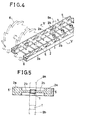
- the carrying member 2 is made of the same material as that of the capsules 1, and the capsules 1 and the carrying member 2 are formed integrally one with another so as to form, as a whole, a belt-shaped one of, for instance, 22 mm in width, as shown clearly in Fig. 4.
- the carrying member 2 are composed of a pair of right and left long base members 2a, 2a disposed to leave a space of, for instance, 12 mm therebetween, and each of those members is, for instance, 4 mm in thickness and 5 mm in width, and the plural capsules 1 are disposed in a row to leave a regular space therebetween in the space formed between the two members 2a, 2a and each of those capsules is connected to those two members 2a, 2a through a pair of fixing members 2b, 2b each being 1 mm in diameter, extending inwards from those members 2a, 2a.
- Numeral 2c denotes a plurality of regularly spaced reinforcing members, each being, for instance, 1 mm in diameter which connects between the two base members 2a, 2a.
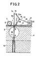
- the carrying member 2 is placed movably along on an upper surface of a machine body 4 having therein a shock wave generating chamber 3, and the member 2 is provided with at least one row of concave or dent portions 5 disposed at regular intervals, and is connected, through at least one gear 6 meshed with those concave portions 5, to an electric motor 7 so as to be movable along on the machine body 4 by the motor 7.
- the member 2 is provided with two rows of the concave portions provided made in the pair of the long base members 2a, 2a, and is connected through the pair of the right and left gears 6 to the motor 7.
- the machine body 4 is provided therein with a through opening 8 which passes therethrough vertically so as to be in communication with the shock wave generating chamber 3, and an explosive capsule holding rod 9a is provided movably upwards and downwards and is located in an ordinary condition above the carrying member 2 so as to face the through opening 8, and another explosive capsule holding rod 9b always urged by a spring 10 upwards is slidably inserted in the through opening 8 and is restricted in its upward movement by a stopper 11, so as to be ordinarly kept in such a condition that an upper end thereof is brought in contact with a lower surface of the carrying member 2.
- the holding rod 9a is so connected with a driving means 13 that, if driven, the same may contact the selected explosive capsule 1 for holding it between the same and the other holding rod 9b, and if further driven, the selected explosive capsule 1 may be forced to be separated, by shearing, from the carrying member 2 and further be moved to a predetermined position in the shock wave generating chamber 3, that is, a first focus position 12 of the chamber 3 of which a wall surface has a shape of a part of pseudo-ellipsoid of revolution.
- the driving means 13 is so constructed that a rod member 16 which is pivotally attached at its one end to a fork shaped member 15, which is engaged with a smaller diametrical part 14 of an upper end portion of the holding rod 9a, and is so supported as to be movable upwards and downwards through a guide member 15a, and a rod member 18 which is pivotally attached at its one end to a base member 17 are pivotally attached at their other ends to one end of a rack 19, and the rack 19 is connected, through a pinion 20 and a gear not illustrated, to an electric motor 21.
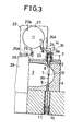
- the electric motor 21 comprises, for instance, a stepping motor, and at each time when it turns in its regular direction, it causes the holding rod 9a to move downwards by a predetermined distance from its position shown in Fig. 1 to its position shown in Fig.3, and at each time when it turns in the reverse direction, it causes the holding rod 9a to move upwards by a predetermined distance from its position shown in Fig. 3 to its position shown in Fig. 1.
- a striking means 22 serving to strike an upper end of the holding rod 9a under such a condition that the rod 9a is in its position shown in Fig. 3.
- the striking means 22 comprises a striking member 24 urged by the force of a spring 23, a restraining member 25 urged by a spring 25a for restraining the member 24 at a readiness position, a push member 26 for pushing the restraining member 25 in the direction of an arrow shown in Fig. 1, and a returning member 27 with an engaging pin 27a for returning the striking member 24 to its readiness position.
- the push member 26 such as a piston of a piston cylinder or the like is operated, the striking means 22 is changed from its inoperative condition shown in Fig.
- the electric motor 7 for moving the carrying member 2 comprises, for instance, a stepping motor, and at each time when it is operated, the carrying member 2 is moved by one pitch of the explosive capsules 1, and each starting operation thereof is made by a limit switch (not illustrated) arranged to be closed at each time when the holding rod 9a reaches its position shown in Fig. 1.
- numeral 28 denotes a liquid tank which is in communication with the shock wave generating chamber 3 and serves to immerse a human body to be treated.
- each capsule 1 is charged with an explosive, and an upper surface thereof is tightly closed with a coating of quick drying paste or adhesive.
- the carrying member 2 is placed on the upper surface of the machine body 4.
- Each capsule 1 is located in the middle space between the long base members 2a, 2a of the carrying member 2 and i F fixed thereto through the pair of the fixing members 2b, 2b so that there is not such a fear that the same might be exploded accidentally by a shock given during conveying of the carrying member 2.
- the holding rod 9a is further lowered, the connecting portions of the capsule 1 with the fixing members 2b, 2b, are sheared, so that the capsule 1 is separated from the carrying member 2, and thereafter is introduced into the shock wave generating chamber 3 under the condition that the same is held firmly between the two holding rods 9a, 9b.
- the electric motor 21 is stopped in operation, so that the two holding rods 9a, 9b are stopped. If, at this stage, the push member 26 is advanced to push the restraining member 25, the restraining member 25 is disengaged from the striking member 24, and the striking member 24 is turned by the force of the spring 23 to strike the upper end of the holding rod 9a.
- the electric motor 21 is turned in the reverse direction, so that the holding rod 9a is returned upwards to its original position, and meanwhile the striking means 22 is also returned to its readiness condition by the rotation of the returning member 27.
- the electric motor 7 is started in operation, so that the carrying member 2 is moved by one pitch, and the next explosive casule 1 is positioned to be in alignment with the axes of the two supporting rods 9a, 9b.
- the lowering movement of the holding rod 9a, the elevating movement of the same, and the advancing movement of the push member 26 of the striking means 22 are started, respectively, by respective manual operations, but such a modification can be considered that there is provided a limit switch arranged to be closed by the lower limit position of the holding rod 9a, and a timer switch responsive thereto, so that if only the lowering movement of the holding rod 9a is started by a manual operation, the other operations can be obtained in order automatically.
- the apparatus is used for an apparatus for disintegrating a calculus in a human body, but may be applied to any other apparatus utilizing a shock wave such as a molding apparatus or the like.
- plural explosive capsules carried on a carrying member are arranged to be selectively brought one after another to a predetermined position for being exploded, so that the operation of the apparatus can be facilitated and the construction thereof is simple.
Applications Claiming Priority (2)
| Application Number | Priority Date | Filing Date | Title |
|---|---|---|---|
| JP1985157789U JPS635699Y2 (de) | 1985-10-17 | 1985-10-17 | |
| JP157789/85 | 1985-10-17 |
Publications (2)
| Publication Number | Publication Date |
|---|---|
| EP0219820A2 true EP0219820A2 (de) | 1987-04-29 |
| EP0219820A3 EP0219820A3 (de) | 1988-09-14 |
Family
ID=15657325
Family Applications (1)
| Application Number | Title | Priority Date | Filing Date |
|---|---|---|---|
| EP86114354A Withdrawn EP0219820A3 (de) | 1985-10-17 | 1986-10-16 | Intermittierendes Explosionsgerät |
Country Status (5)
| Country | Link |
|---|---|
| US (1) | US4722281A (de) |
| EP (1) | EP0219820A3 (de) |
| JP (1) | JPS635699Y2 (de) |
| CN (1) | CN1006444B (de) |
| AU (1) | AU590011B2 (de) |
Cited By (1)
| Publication number | Priority date | Publication date | Assignee | Title |
|---|---|---|---|---|
| CN1068112C (zh) * | 1997-09-09 | 2001-07-04 | 湖南省向红机械厂 | 复式雷管自动装填机 |
Families Citing this family (1)
| Publication number | Priority date | Publication date | Assignee | Title |
|---|---|---|---|---|
| JP2015203572A (ja) * | 2014-04-10 | 2015-11-16 | 株式会社アミック | 人工構造物の非破壊検査方法 |
Citations (5)
| Publication number | Priority date | Publication date | Assignee | Title |
|---|---|---|---|---|
| US2459147A (en) * | 1949-01-18 | Disintegrating cartridge belt | ||
| GB1193507A (en) * | 1966-06-14 | 1970-06-03 | Inst Francais Du Petrole | System for Seismic Prospecting in Water |
| DE2724324B1 (de) * | 1977-05-28 | 1978-08-31 | Philips Patentverwaltung | Vorrichtung zum Zertruemmern von Blasensteinen |
| US4196736A (en) * | 1976-07-09 | 1980-04-08 | Hiroki Watanabe | Apparatus for crushing a calculus |
| EP0206331A2 (de) * | 1985-06-26 | 1986-12-30 | Yachiyoda Sangyo Co., Ltd. | Vorrichtung zur Zertrümmerung von Nierensteinen mittels ausserhalb des menschlichen Körpers erzeugter Unterwasserstosswellen |
Family Cites Families (8)
| Publication number | Priority date | Publication date | Assignee | Title |
|---|---|---|---|---|
| US2821921A (en) * | 1956-08-28 | 1958-02-04 | Thomas B Martin | Well shooting unit utilizing a porous enclosing body |
| US2999458A (en) * | 1958-07-01 | 1961-09-12 | Du Pont | Surface wave generator |
| US3088378A (en) * | 1960-07-05 | 1963-05-07 | John L Boudreau | Pistol with slidable and fixed breech block |
| US3687074A (en) * | 1962-08-24 | 1972-08-29 | Du Pont | Pulse producing assembly |
| US3720133A (en) * | 1970-08-26 | 1973-03-13 | H Bouix | Infantry weapon adapted to fire a plurality of cartridges simultaneously |
| DE3328068A1 (de) * | 1983-08-03 | 1985-02-21 | Siemens AG, 1000 Berlin und 8000 München | Einrichtung zum beruehrungslosen zertruemmern von konkrementen |
| JPS6116735A (ja) * | 1984-07-03 | 1986-01-24 | 京都府 | 結石破砕装置 |
| US4620545A (en) * | 1984-10-31 | 1986-11-04 | Trutek Research, Inc. | Non-invasive destruction of kidney stones |
-
1985
- 1985-10-17 JP JP1985157789U patent/JPS635699Y2/ja not_active Expired
-
1986
- 1986-10-14 US US06/918,153 patent/US4722281A/en not_active Expired - Fee Related
- 1986-10-14 CN CN86107202A patent/CN1006444B/zh not_active Expired
- 1986-10-16 AU AU63983/86A patent/AU590011B2/en not_active Ceased
- 1986-10-16 EP EP86114354A patent/EP0219820A3/de not_active Withdrawn
Patent Citations (5)
| Publication number | Priority date | Publication date | Assignee | Title |
|---|---|---|---|---|
| US2459147A (en) * | 1949-01-18 | Disintegrating cartridge belt | ||
| GB1193507A (en) * | 1966-06-14 | 1970-06-03 | Inst Francais Du Petrole | System for Seismic Prospecting in Water |
| US4196736A (en) * | 1976-07-09 | 1980-04-08 | Hiroki Watanabe | Apparatus for crushing a calculus |
| DE2724324B1 (de) * | 1977-05-28 | 1978-08-31 | Philips Patentverwaltung | Vorrichtung zum Zertruemmern von Blasensteinen |
| EP0206331A2 (de) * | 1985-06-26 | 1986-12-30 | Yachiyoda Sangyo Co., Ltd. | Vorrichtung zur Zertrümmerung von Nierensteinen mittels ausserhalb des menschlichen Körpers erzeugter Unterwasserstosswellen |
Cited By (1)
| Publication number | Priority date | Publication date | Assignee | Title |
|---|---|---|---|---|
| CN1068112C (zh) * | 1997-09-09 | 2001-07-04 | 湖南省向红机械厂 | 复式雷管自动装填机 |
Also Published As
| Publication number | Publication date |
|---|---|
| EP0219820A3 (de) | 1988-09-14 |
| JPS635699Y2 (de) | 1988-02-17 |
| AU6398386A (en) | 1987-04-30 |
| JPS6266611U (de) | 1987-04-25 |
| CN1006444B (zh) | 1990-01-17 |
| US4722281A (en) | 1988-02-02 |
| AU590011B2 (en) | 1989-10-26 |
| CN86107202A (zh) | 1987-05-13 |
Similar Documents
| Publication | Publication Date | Title |
|---|---|---|
| US4715514A (en) | Automatic unitary product dispensing device | |
| US3487965A (en) | Device and method of dispensing container contents | |
| EP0219820A2 (de) | Intermittierendes Explosionsgerät | |
| US3468024A (en) | Method and apparatus for orienting and assembling small parts | |
| EP0206331A2 (de) | Vorrichtung zur Zertrümmerung von Nierensteinen mittels ausserhalb des menschlichen Körpers erzeugter Unterwasserstosswellen | |
| JPS6421399A (en) | Fuel rod takeoff apparatus, withdrawal of fuel rod, capacity reducer, use of extrusion rod and transfer of fuel rod | |
| US1441196A (en) | Conveying mechanism for dry-battery machines | |
| GR3000973T3 (en) | After-firing safety device for a missile with an impact fuse | |
| DE2844386A1 (de) | Batterie mit beschleunigungsaktivierung | |
| DE102004034784B4 (de) | Verfahren und Vorrichtung zur Delaborierung von explosivstoffhaltigen Körpern | |
| US4178672A (en) | Apparatus for assembling and banding an expansion shell | |
| US4594834A (en) | Container stuffing apparatus and method | |
| JPS5719121A (en) | Forging apparatus of product having a set head | |
| JPS56119700A (en) | Safety device for machine tool | |
| US3323405A (en) | Cartridge reloading device | |
| US1462185A (en) | Dkoppina machine | |
| DE727271C (de) | Zuender mit Zerlegerwirkung | |
| US4409878A (en) | Cartridge primer seating tool | |
| US3353735A (en) | Apparatus for preparing candy apples | |
| SU1178582A1 (ru) | Пороховой монтажный инструмент | |
| SU640793A1 (ru) | Устройство дл ориентации и поштучной выдачи стержневых заготовок | |
| DE1628010A1 (de) | Explosionsbetriebenes Werkzeug | |
| RU36851U1 (ru) | Взрывное устройство для резки удлиненных изделий | |
| JPH0451958B2 (de) | ||
| CN114295019A (zh) | 一种机械式定时起爆装置 |
Legal Events
| Date | Code | Title | Description |
|---|---|---|---|
| PUAI | Public reference made under article 153(3) epc to a published international application that has entered the european phase |
Free format text: ORIGINAL CODE: 0009012 |
|
| AK | Designated contracting states |
Kind code of ref document: A2 Designated state(s): AT BE CH DE FR GB IT LI LU NL SE |
|
| PUAL | Search report despatched |
Free format text: ORIGINAL CODE: 0009013 |
|
| AK | Designated contracting states |
Kind code of ref document: A3 Designated state(s): AT BE CH DE FR GB IT LI LU NL SE |
|
| 17P | Request for examination filed |
Effective date: 19890213 |
|
| STAA | Information on the status of an ep patent application or granted ep patent |
Free format text: STATUS: THE APPLICATION HAS BEEN WITHDRAWN |
|
| 18W | Application withdrawn |
Withdrawal date: 19900221 |
|
| RIN1 | Information on inventor provided before grant (corrected) |
Inventor name: KIMURA, SHUZO |