EP0219283A2 - Variable capacity wobble plate type compressor - Google Patents
Variable capacity wobble plate type compressor Download PDFInfo
- Publication number
- EP0219283A2 EP0219283A2 EP86307663A EP86307663A EP0219283A2 EP 0219283 A2 EP0219283 A2 EP 0219283A2 EP 86307663 A EP86307663 A EP 86307663A EP 86307663 A EP86307663 A EP 86307663A EP 0219283 A2 EP0219283 A2 EP 0219283A2
- Authority
- EP
- European Patent Office
- Prior art keywords
- pressure
- crank chamber
- disposed
- wobble plate
- valve element
- Prior art date
- Legal status (The legal status is an assumption and is not a legal conclusion. Google has not performed a legal analysis and makes no representation as to the accuracy of the status listed.)
- Granted
Links
Images
Classifications
-
- F—MECHANICAL ENGINEERING; LIGHTING; HEATING; WEAPONS; BLASTING
- F04—POSITIVE - DISPLACEMENT MACHINES FOR LIQUIDS; PUMPS FOR LIQUIDS OR ELASTIC FLUIDS
- F04B—POSITIVE-DISPLACEMENT MACHINES FOR LIQUIDS; PUMPS
- F04B13/00—Pumps specially modified to deliver fixed or variable measured quantities
-
- F—MECHANICAL ENGINEERING; LIGHTING; HEATING; WEAPONS; BLASTING
- F04—POSITIVE - DISPLACEMENT MACHINES FOR LIQUIDS; PUMPS FOR LIQUIDS OR ELASTIC FLUIDS
- F04B—POSITIVE-DISPLACEMENT MACHINES FOR LIQUIDS; PUMPS
- F04B27/00—Multi-cylinder pumps specially adapted for elastic fluids and characterised by number or arrangement of cylinders
- F04B27/08—Multi-cylinder pumps specially adapted for elastic fluids and characterised by number or arrangement of cylinders having cylinders coaxial with, or parallel or inclined to, main shaft axis
- F04B27/10—Multi-cylinder pumps specially adapted for elastic fluids and characterised by number or arrangement of cylinders having cylinders coaxial with, or parallel or inclined to, main shaft axis having stationary cylinders
- F04B27/1036—Component parts, details, e.g. sealings, lubrication
- F04B27/1054—Actuating elements
- F04B27/1072—Pivot mechanisms
-
- F—MECHANICAL ENGINEERING; LIGHTING; HEATING; WEAPONS; BLASTING
- F04—POSITIVE - DISPLACEMENT MACHINES FOR LIQUIDS; PUMPS FOR LIQUIDS OR ELASTIC FLUIDS
- F04B—POSITIVE-DISPLACEMENT MACHINES FOR LIQUIDS; PUMPS
- F04B27/00—Multi-cylinder pumps specially adapted for elastic fluids and characterised by number or arrangement of cylinders
- F04B27/08—Multi-cylinder pumps specially adapted for elastic fluids and characterised by number or arrangement of cylinders having cylinders coaxial with, or parallel or inclined to, main shaft axis
- F04B27/14—Control
- F04B27/16—Control of pumps with stationary cylinders
- F04B27/18—Control of pumps with stationary cylinders by varying the relative positions of a swash plate and a cylinder block
- F04B27/1804—Controlled by crankcase pressure
- F04B2027/1809—Controlled pressure
- F04B2027/1813—Crankcase pressure
-
- F—MECHANICAL ENGINEERING; LIGHTING; HEATING; WEAPONS; BLASTING
- F04—POSITIVE - DISPLACEMENT MACHINES FOR LIQUIDS; PUMPS FOR LIQUIDS OR ELASTIC FLUIDS
- F04B—POSITIVE-DISPLACEMENT MACHINES FOR LIQUIDS; PUMPS
- F04B27/00—Multi-cylinder pumps specially adapted for elastic fluids and characterised by number or arrangement of cylinders
- F04B27/08—Multi-cylinder pumps specially adapted for elastic fluids and characterised by number or arrangement of cylinders having cylinders coaxial with, or parallel or inclined to, main shaft axis
- F04B27/14—Control
- F04B27/16—Control of pumps with stationary cylinders
- F04B27/18—Control of pumps with stationary cylinders by varying the relative positions of a swash plate and a cylinder block
- F04B27/1804—Controlled by crankcase pressure
- F04B2027/1822—Valve-controlled fluid connection
- F04B2027/1831—Valve-controlled fluid connection between crankcase and suction chamber
-
- F—MECHANICAL ENGINEERING; LIGHTING; HEATING; WEAPONS; BLASTING
- F04—POSITIVE - DISPLACEMENT MACHINES FOR LIQUIDS; PUMPS FOR LIQUIDS OR ELASTIC FLUIDS
- F04B—POSITIVE-DISPLACEMENT MACHINES FOR LIQUIDS; PUMPS
- F04B27/00—Multi-cylinder pumps specially adapted for elastic fluids and characterised by number or arrangement of cylinders
- F04B27/08—Multi-cylinder pumps specially adapted for elastic fluids and characterised by number or arrangement of cylinders having cylinders coaxial with, or parallel or inclined to, main shaft axis
- F04B27/14—Control
- F04B27/16—Control of pumps with stationary cylinders
- F04B27/18—Control of pumps with stationary cylinders by varying the relative positions of a swash plate and a cylinder block
- F04B27/1804—Controlled by crankcase pressure
- F04B2027/184—Valve controlling parameter
- F04B2027/1845—Crankcase pressure
Definitions
- the present invention relates to a wobble plate type compressor, for use, for example, in a refrigeration system.
- a wobble plate type compressor which reciprocates pistons by converting the rotational movement of a cam rotor into nutational movement of a wobble plate, is well known.
- a variable capacity mechanism which changes the compression capacity is also well known, as shown in US-A-3,861,829.
- piston displacement is altered by varing the angle of the inclined surface of the cam rotor by a pressure difference between the crank chamber, in which the cam rotor is disposed, and the suction chamber under the condition that the suction pressure is maintained at a predetermined level by controlling the amount of outflow refrigerant from the crank chamber.
- the compression capacity of the compressor varies with the piston displacement.
- the level of suction pressure at which the variable capacity mechanism starts its operation is not determined at a lower value, because the suction pressure of the refrigerant corresponds to the evaporating temperature of the refrigerant. If the suction pressure is determined at a lower value, freezing on the surface of the evaporator is generated. Thus, the pull-down characteristic of the compressor is not sufficient. Also, because the pressure in the crank chamber is controlling and the volume of the crank chamber is larger than that of the suction chamber, piston response to a change in the angle of the inclined surface of the cam rotor is not adequate. Furthermore, when the pressure difference between the crank chamber and the suction chamber changes, oil may flow into the crank chamber from the suction chamber.
- a wobble plate type compressor with a variable capacity mechanism the compressor comprises a cylindrical casing including a cylinder block and a crank chamber; a plurality of cylinders disposed within the cylinder block; a plurality of pistons, each reciprocatingly disposed in a respective one of the cylinders; a rotatable drive shaft supported on the cylindrical casing; a rotor mounted on and rotatable with the drive shaft, and having an inclined plate, the angle of which relatively to the drive shaft is variable by the variable capacity mechanism; a wobble plate coupled to the pistons and being arranged to nutate in response to rotation of the rotor to reciprocate the pistons, the wobble plate being disposed on the inclined plate of the rotor; is characterised in that the variable capacity mechanism includes a passageway interconnecting the crank chamber and a suction chamber; a valve element to control the opening and closing of the passageway, and a control device to control the operation of the valve element, the control device having a pressure detecting element responsive to
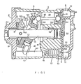
- Figure 1 shows a wobble plate type compressor 1 which includes a front end plate 2, a cylinder casing 3 having cylinder block 31, a valve plate 4, and a cylinder head 5.
- the front end plate 2 is fixed on one end opening of the cylinder casing 3 by securing bolts (not shown).
- An axial hole 21 is formed through the centre of the front end plate 2 for the penetration of a drive shaft 7.
- a radial bearing 8 is disposed in the axial hole 21 to support rotatably the drive shaft 7.
- An annular sleeve portion 22 projects from the front end plate 2 and surrounds the drive shaft 7 for defining a seal cavity 23.
- the cylinder casing 3 is provided with the cylinder block 31 and a crank chamber 32.
- the cylinder block 31 has a plurality of equiangularly spaced cylinders 33.
- a cam rotor 10 is fixed on the drive shaft 7.
- a thrust needle bearing 11 is disposed between the inner wall surface of the front end plate 2 and the adjacent axial end surface of the cam rotor 10.
- An arm portion 101 of the cam rotor 10 extends in the direction of the cylinder block 31.
- An elongate hole 102 is formed on the arm portion 101.
- a cylindrical member 12, provided with a flange portion 121, is disposed around the drive shaft 7 and is nutatable supported on the drive shaft 7 through a spherical element 13 slidable fitted on the drive shaft 7.
- a second arm portion 122 is formed on the outer surface of the flange portion 121 of the cylindrical member 12 and faces the arm portion 101 of the cam rotor 10.
- a ring-shaped wobble plate 15 is mounted on the outer surface of the cylindrical member 12 through a radial needle bearing 16.
- a thrust needle bearing 17 is disposed in a gap between the flange portion 121 and the ring-shaped wobble plate 15.
- the other end of the drive shaft 7 is rotatably supported through a radial bearing 18 in the a central bore of the cylinder block 31.
- a sliding shaft 151 is attached to the wobble plate 15 and projects towards the bottom surface of the cylinder casing 3. The end of the sliding shaft 151 is slidably disposed in a groove 321 to prevent the rotation of the wobble plate 15.
- each of a plurality of piston rods 19 is rotatably connected to a receiving-surface 152 of the wobble plate 15.
- the other end of the piston rod 19 is rotatably connected to its piston 20, which is slidably disposed in its cylinder 33.
- Suction ports 41 and discharge ports 42 are formed through the valve plate 4.
- a suction reed valve (not shown) is disposed on the valve plate 4.
- a discharge reed valve (not shown) is also disposed on the side of the valve plate 4 opposite to the suction reed valve.
- the cylinder head 5 is connected to the cylinder casing 3 through a gasket and the valve plate 4.
- a partition wall 51 extends axially from the inner surface of the cylinder head 5 and divides the interior of the cylinder head 5 into two chambers: a suction chamber 52 and a discharge chamber 53.
- the suction chamber 52 is connectable with an external fluid refrigerant circuit through a fluid inlet port 60 formed on the cylinder head 5.
- the discharge chamber 53 is also connected with the external fluid circuit through a fluid outlet port 61 formed on the cylinder head 5.
- a cylindrical bore 62 is formed in the cylinder block 31 and disposed therein is a bellows 63.
- the bore 62 communicates with the suction chamber 52 through a passage in the form of an aperture 64 formed in the valve plate 4, and also communicates with the crank chamber 32 through a connecting passage 65 formed in the cylinder block 31.
- the aperture 64 is normally closed by a needle valve element 631 attached on one end portion of the bellows 63. Therefore, the bore 62 is normally connected with the crank chamber 32 through the passage 65.
- rotational motion is applied to the drive shaft 7 by a driving source and is transmitted to the cam rotor 10 from the drive shaft 7.
- the rotational motion of the cam rotor 10 is transmitted to the wobble plate 15 through the cylindrical member 12.
- the sliding shaft 151 connected to the wobble plate 15 and disposed in the groove 321, prevents the wobble plate 15 from rotating.
- the rotational motion transmitted from the cam rotor 10 and cylindrical member 12 is converted to nutational motion of the wobble plate 15.
- each piston 20 reciprocates within its cylinder 33 through its piston rod 19. Accordingly, refrigerant gas is sucked from the inlet port 60 through the suction chamber 52 and flows in turn into the cylinders 33 through the suction ports 41. Then, refrigerant gas is compressed in the cylinders 33 and is discharged into the discharge chamber 53 through the discharge ports 42. Compressed refrigerant gas in the discharge chamber 53 flows into the external fluid circuit through the outlet port 61.
- Fp which is the force acting on the rear surface of the pistons 19 is calculated from the following equation: wherein n is the number of pistons, Pc is the pressure in the crank chamber, and S is the area of a piston which receives the pressure in the crank chamber.
- the gross gas pressure ⁇ Fpi can be determined from the following equation: where -FR represents the direction of frictional force when the compressor is operated to reduce the capacity, and +FR represents the direction of frictional force when the compressor is operated to increase the capacity.
- the equation for conservation of moment around the point (P) can be derived from equation (1) and is as follows:
- the cylindrical member 12 and wobble plate 15 change their angle of inclination to conserve moment.
- equation (2) a variation in the angle of inclination of the wobble plate is obtained by a change in the force Fp.
- Prior control devices normally change the force Fp by changing the pressure in the crank chamber while maintaining the suction pressure uniform.
- a change of pressure in the crank chamber is used as the origin of varying the angle of inclination of the wobble plate, several disadvantages result, as mentioned above.
- FIGS 3 and 4 illustrate the method of controlling the variable capacity of the above described compressor.
- the cylindrical bore 62 in which the bellows 63 is disposed is usually connected with the crank chamber 32 through the passage 65. Therefore, if the pressure Pc in the crank chamber exceeds the pressure within the bellows 63 owing to leakage past the pistons, the bellows 63 is retracted and opens the aperture 64, Thus, the gas in the crank chamber 32 flows out to the suction chamber 52 through the passageway 65,62,64. On the other hand, if the pressure in the crank chamber is less than the pressure in the bellows 63, the bellows 63 is extended. The aperture 64 is thus closed by the needle element 631 to cause an increase in the pressure Pc in the crank chamber 32 owing to leakage.
- the change of pressure in the crank chamber 32 can thus be maintained within a small range, i.e., nearly at a predetermined level (in Figure 3, the pressure P is the central point of the predetermined level). Therefore, the angle of inclination of the cylindrical member 12 and the wobble plate 15 is varied by the pressure difference between the crank chamber 32 and the suction chamber 52, i.e., Fpi shown in equation (2) is changeable to change the moment around the point (p).
- the pressure in the crank chamber (Pc) is initially dropped, but is quickly stabilized to maintain the predetermined level, as shown in Figure 4a.
- the suction pressure (Ps) of refrigerant is continuously reduced upon reduction of heat load, i.e., temperature in the refrigerated compartment.
- the capacity control is operated to realize the equation (2). That is the angle of the cylindrical member 12 and wobble plate 15 is changed to reduce the capacity of the compressor. If the suction pressue (Ps) is increased owing to a decrease in the capacity of the compressor, and reaches the point (b) in Figure 4a, the reduction in the angle of the cylindrical member 12 and wobble plate 15 ceases. Therefore, the compressor still continues operation at the reduced capacity.
- the change of suction pressure compensated to the change of heat load is varied within a predetermined range, as shown in Figure 4b. That is, when the heat load, i.e. the temperature in the compartment, is reduced, the suction pressure ( P s) is changed as shown by dot and chain line in Figure 4b. On the other hand, when the heat load is increased, the suction pressure (Ps) is changed as shown by dotted line in Figure 4b.
- the operational points to reduce the capacity, and to increase the capacity are different from one another.
- the difference between pressure in the crank chamber and in the suction chamber to cause change in the angle of the cylindrical member 12 and wobble plate 15 has a different characteristic when the capacity of the compressor is to be reduced or increased. That is the operation of varying the capacity of the compressor exhibits hysteresis. This hysteresis is caused by the frictional force and is determined by the angle p, the position of the connecting member between the rotor 10 and the cylindrical member 12, or the coefficient of friction p.
- the difference of the operational point generates a differential, i.e., the temperature in the compartment is variable because of the difference of the operational points.
- this temperature variation may be controlled within a small range by appropriate selection of the parameters of equation, for example, the angle p, the coefficient of friction p and the position of the connecting member.
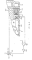
- FIG. 5 shows another compressor with a different valve for controlling the capacity control mechanism. Similar parts are represented by the same reference numbers as in the compressor shown in Figure 1, and any description of two similar parts is omitted to simplify the description.
- An electromagnetic valve means 100 is disposed within the cylindrical bore 62, and a valve element 101 controls the opening and closing of the aperture 64.
- a pressure detecting means 110 is diposed on the cylindrical casing 3 to detect the pressure in the passageway 65, i.e., in the crank chamber 32.
- the detection signal of the pressure detecting means 110 is input to a comparator 120 and compared with a predetermined reference voltage which corresponds to the predetermined pressure in the crank chamber 32.
- the output terminal of the comparator 120 is connected with a coil 141 of a relay 140 and a zener diode 150 through a relay controller 130.
- the relay 140 has a normal closed terminal, and one terminal is connected to a coil 102 of the electromagnetic valve means 100. Therefore, movement of the valve element 101, i.e. opening and closing of the aperture, is controlled by operation of the relay 140.
- the detection signal of the pressure detecting means 110 is compared with a reference voltage level, and as a result, the higher level signal, such as a positive voltage, is output from the comparator 120.
- the positive voltage from the comparator 120 is amplified to exceed the voltage of the source by the relay controller 130. Therefore, current is supplied to the coil 102 of the electromagnetic valve means 100 through the zener diode 150. As a result of energization of the coil 102, the valve element 101 is attracted to open the aperture 63. At the time, the refrigerant gas contained within the crank chamber 32 flows out to the suction chamber 52 through the passage 65, bore 62 and aperture 63.
- the low voltage signal such as zero or negative voltage
- the comparator 120 the low voltage signal, such as zero or negative voltage
- the current from the power source is applied to the coil 141 of the relay 140 to energise the relay 140 and thereby open the relay 140.
- the valve element 101 is urged towards the valve plate 4 to close the aperture 63.
- the pressure in the crank chamber 32 can therefore be increased by leakage gas.
- variable displacement (capacity) mechanism of this invention is controlled by change of suction pressure, while maintaining the pressure in the crank chamber at a predetermined level.
- the evaporating temperature of refrigerant for starting the operation of the variable displacement mechanism can be set at a lower level without generation of freezing on the evaporator. Therefore, the pull-down characteristic of the compressor is improved.
- the pressure in the crank chamber is usually uniformly maintained within a predetermined range so that oil contained within the crank chamber is prevented from flowing out.
Abstract
Description
- The present invention relates to a wobble plate type compressor, for use, for example, in a refrigeration system.
- A wobble plate type compressor, which reciprocates pistons by converting the rotational movement of a cam rotor into nutational movement of a wobble plate, is well known. A variable capacity mechanism which changes the compression capacity is also well known, as shown in US-A-3,861,829. In this mechanism, piston displacement is altered by varing the angle of the inclined surface of the cam rotor by a pressure difference between the crank chamber, in which the cam rotor is disposed, and the suction chamber under the condition that the suction pressure is maintained at a predetermined level by controlling the amount of outflow refrigerant from the crank chamber. Thus, the compression capacity of the compressor varies with the piston displacement.
- One of the disadvantages of the above mechanism is that the level of suction pressure at which the variable capacity mechanism starts its operation is not determined at a lower value, because the suction pressure of the refrigerant corresponds to the evaporating temperature of the refrigerant. If the suction pressure is determined at a lower value, freezing on the surface of the evaporator is generated. Thus, the pull-down characteristic of the compressor is not sufficient. Also, because the pressure in the crank chamber is controlling and the volume of the crank chamber is larger than that of the suction chamber, piston response to a change in the angle of the inclined surface of the cam rotor is not adequate. Furthermore, when the pressure difference between the crank chamber and the suction chamber changes, oil may flow into the crank chamber from the suction chamber.
- In accordance with the invention, a wobble plate type compressor with a variable capacity mechanism, the compressor comprises a cylindrical casing including a cylinder block and a crank chamber; a plurality of cylinders disposed within the cylinder block; a plurality of pistons, each reciprocatingly disposed in a respective one of the cylinders; a rotatable drive shaft supported on the cylindrical casing; a rotor mounted on and rotatable with the drive shaft, and having an inclined plate, the angle of which relatively to the drive shaft is variable by the variable capacity mechanism; a wobble plate coupled to the pistons and being arranged to nutate in response to rotation of the rotor to reciprocate the pistons, the wobble plate being disposed on the inclined plate of the rotor; is characterised in that the variable capacity mechanism includes a passageway interconnecting the crank chamber and a suction chamber; a valve element to control the opening and closing of the passageway, and a control device to control the operation of the valve element, the control device having a pressure detecting element responsive to the pressure in the crank chamber and being arranged to control the valve element to maintain the pressure in the crank chamber substantially at a predetermined level as a result of comparing the crank chamber pressure with a predetermined value.
- Two examples of compressors constructed in accordance with the invention are illustrated in the accompanying drawings, in which:-
- Figure 1 is a vertical section through one compressor;
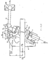
- Figure 2 is a diagrammatic view of an angle varying mechanism of the compressor of Figure 1s
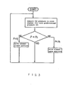
- Figure 3 is block diagram of a control device for the angle varying mechanism;
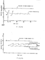
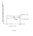
- Figures 4a and 4b are graphs illustrating the change of suction pressure and pressure in the crank chamber with operating time;
- Figure 4c is a graph illustrating the relation between the compressed volume and pressure difference between the pressure in the crank chamber and in the suction chamber; and,
- Figure 5 is a partly section view of the variable capacity mechanism of the second example of compressor.
- Figure 1 shows a wobble
plate type compressor 1 which includes afront end plate 2, acylinder casing 3 havingcylinder block 31, avalve plate 4, and acylinder head 5. Thefront end plate 2 is fixed on one end opening of thecylinder casing 3 by securing bolts (not shown). Anaxial hole 21 is formed through the centre of thefront end plate 2 for the penetration of adrive shaft 7. Aradial bearing 8 is disposed in theaxial hole 21 to support rotatably thedrive shaft 7. Anannular sleeve portion 22 projects from thefront end plate 2 and surrounds thedrive shaft 7 for defining aseal cavity 23. Thecylinder casing 3 is provided with thecylinder block 31 and acrank chamber 32. Thecylinder block 31 has a plurality of equiangularly spacedcylinders 33. - A
cam rotor 10 is fixed on thedrive shaft 7. A thrust needle bearing 11 is disposed between the inner wall surface of thefront end plate 2 and the adjacent axial end surface of thecam rotor 10. Anarm portion 101 of thecam rotor 10 extends in the direction of thecylinder block 31. Anelongate hole 102 is formed on thearm portion 101. Acylindrical member 12, provided with aflange portion 121, is disposed around thedrive shaft 7 and is nutatable supported on thedrive shaft 7 through aspherical element 13 slidable fitted on thedrive shaft 7. Asecond arm portion 122 is formed on the outer surface of theflange portion 121 of thecylindrical member 12 and faces thearm portion 101 of thecam rotor 10. Ahole 123, formed in thearm portion 122, is aligned with theelongate hole 102. Apin 14, inserted through thehole 123, is slidably movable within theelongate hole 102. A ring-shaped wobble plate 15 is mounted on the outer surface of thecylindrical member 12 through a radial needle bearing 16. Also, a thrust needle bearing 17 is disposed in a gap between theflange portion 121 and the ring-shaped wobble plate 15. The other end of thedrive shaft 7 is rotatably supported through a radial bearing 18 in the a central bore of thecylinder block 31. Asliding shaft 151 is attached to thewobble plate 15 and projects towards the bottom surface of thecylinder casing 3. The end of thesliding shaft 151 is slidably disposed in agroove 321 to prevent the rotation of thewobble plate 15. - One end of each of a plurality of
piston rods 19 is rotatably connected to a receiving-surface 152 of thewobble plate 15. The other end of thepiston rod 19 is rotatably connected to itspiston 20, which is slidably disposed in itscylinder 33. -
Suction ports 41 anddischarge ports 42 are formed through thevalve plate 4. A suction reed valve (not shown) is disposed on thevalve plate 4. A discharge reed valve (not shown) is also disposed on the side of thevalve plate 4 opposite to the suction reed valve. Thecylinder head 5 is connected to thecylinder casing 3 through a gasket and thevalve plate 4. Apartition wall 51 extends axially from the inner surface of thecylinder head 5 and divides the interior of thecylinder head 5 into two chambers: asuction chamber 52 and adischarge chamber 53. Thesuction chamber 52 is connectable with an external fluid refrigerant circuit through a fluid inlet port 60 formed on thecylinder head 5. Thedischarge chamber 53 is also connected with the external fluid circuit through a fluid outlet port 61 formed on thecylinder head 5. - A cylindrical bore 62 is formed in the
cylinder block 31 and disposed therein is abellows 63. The bore 62 communicates with thesuction chamber 52 through a passage in the form of anaperture 64 formed in thevalve plate 4, and also communicates with thecrank chamber 32 through a connectingpassage 65 formed in thecylinder block 31. Theaperture 64 is normally closed by aneedle valve element 631 attached on one end portion of thebellows 63. Therefore, the bore 62 is normally connected with thecrank chamber 32 through thepassage 65. - In operation, rotational motion is applied to the
drive shaft 7 by a driving source and is transmitted to thecam rotor 10 from thedrive shaft 7. The rotational motion of thecam rotor 10 is transmitted to thewobble plate 15 through thecylindrical member 12. Thesliding shaft 151, connected to thewobble plate 15 and disposed in thegroove 321, prevents thewobble plate 15 from rotating. The rotational motion transmitted from thecam rotor 10 andcylindrical member 12 is converted to nutational motion of thewobble plate 15. When the wobble plate 15 nutates, eachpiston 20 reciprocates within itscylinder 33 through itspiston rod 19. Accordingly, refrigerant gas is sucked from the inlet port 60 through thesuction chamber 52 and flows in turn into thecylinders 33 through thesuction ports 41. Then, refrigerant gas is compressed in thecylinders 33 and is discharged into thedischarge chamber 53 through thedischarge ports 42. Compressed refrigerant gas in thedischarge chamber 53 flows into the external fluid circuit through the outlet port 61. - The nutational movement of the compressor will be explained with reference to FIgure 2. During the compression stroke of each
cylinder 33, the gas pressure in the cylinder acting against the front of thepiston 19 is Fpi, and the gas pressure in all thecylinders 33 is Σ Fpi. For clarity, only one piston is shown, althrough any number may be used. The gas pressure urges thepiston 19 to the left. The drag at contact point (P) between thepin 14 and theelongate hole 102 is FL, and the angle formed by the drag (FL) with the X-axis, which is the same direction as the central axis of the drive shaft, is β. Therefore, Fp which is the force acting on the rear surface of thepistons 19 is calculated from the following equation:
drive shaft 7 and thespherical element 13 is expressed as p, and the force component of the drag (FL) orthogonal to thedrive shaft 7 is FR (FR=FL.sins). The gross gas pressure Σ Fpi can be determined from the following equation:
- Also, if the Y-axis distance between the point of action (P) of the force on the supporting portion of the
pin 13 and the "E Fpi is Lf, the X-axis distance between the acting point (P) and the component force (FR) is h, the Y-axis distance between the point (P) and central axis of thedrive shaft 7 is L, and the diameter of thedrive shaft 7 is Ds, the equation for conservation of moment around the point (P) can be derived from equation (1) and is as follows:
cylindrical member 12 andwobble plate 15 change their angle of inclination to conserve moment. As clearly understood from equation (2), a variation in the angle of inclination of the wobble plate is obtained by a change in the force Fp. Prior control devices normally change the force Fp by changing the pressure in the crank chamber while maintaining the suction pressure uniform. However, if a change of pressure in the crank chamber is used as the origin of varying the angle of inclination of the wobble plate, several disadvantages result, as mentioned above. - Figures 3 and 4 illustrate the method of controlling the variable capacity of the above described compressor. The cylindrical bore 62 in which the
bellows 63 is disposed is usually connected with thecrank chamber 32 through thepassage 65. Therefore, if the pressure Pc in the crank chamber exceeds the pressure within thebellows 63 owing to leakage past the pistons, thebellows 63 is retracted and opens theaperture 64, Thus, the gas in thecrank chamber 32 flows out to thesuction chamber 52 through thepassageway bellows 63, thebellows 63 is extended. Theaperture 64 is thus closed by theneedle element 631 to cause an increase in the pressure Pc in thecrank chamber 32 owing to leakage. The change of pressure in thecrank chamber 32 can thus be maintained within a small range, i.e., nearly at a predetermined level (in Figure 3, the pressure P is the central point of the predetermined level). Therefore, the angle of inclination of thecylindrical member 12 and thewobble plate 15 is varied by the pressure difference between thecrank chamber 32 and thesuction chamber 52, i.e., Fpi shown in equation (2) is changeable to change the moment around the point (p). - In operation of the refrigerant circuit including the above mentioned compressor, the pressure in the crank chamber (Pc) is initially dropped, but is quickly stabilized to maintain the predetermined level, as shown in Figure 4a. However, the suction pressure (Ps) of refrigerant is continuously reduced upon reduction of heat load, i.e., temperature in the refrigerated compartment.
- After the passage of a predetermined time (to), i.e., when the suction pressure (Ps) has reached a point (a) in Figure 4a, the capacity control is operated to realize the equation (2). That is the angle of the
cylindrical member 12 andwobble plate 15 is changed to reduce the capacity of the compressor. If the suction pressue (Ps) is increased owing to a decrease in the capacity of the compressor, and reaches the point (b) in Figure 4a, the reduction in the angle of thecylindrical member 12 andwobble plate 15 ceases. Therefore, the compressor still continues operation at the reduced capacity. Even if the capacity of the compressor is reduced, the heat load, i.e., the temperature in the compartment, may be gradually reduced, and the suction pressure is reduced (to point c) following the reduction of the heat load. Therefore, the angle of thecylindrical member 12 andwobble plate 15 is again changed to reduced the capacity of the compressor as explained above. Thus, the temperature in the compartment is maintained at a predetermined level. Some term of the equations (1) and (2), such as the frictional force term, are influenced by the change of angle. Therefore, the suction pressure (Ps) changes stepwise, as shown in Figure 4a. - Upon controlling the capacity of the compressor, the change of suction pressure compensated to the change of heat load is varied within a predetermined range, as shown in Figure 4b. That is, when the heat load, i.e. the temperature in the compartment, is reduced, the suction pressure (Ps) is changed as shown by dot and chain line in Figure 4b. On the other hand, when the heat load is increased, the suction pressure (Ps) is changed as shown by dotted line in Figure 4b.
- As clearly shown in Figure 4b, the operational points to reduce the capacity, and to increase the capacity, are different from one another. As shown in Figure 4c, the difference between pressure in the crank chamber and in the suction chamber to cause change in the angle of the
cylindrical member 12 andwobble plate 15, has a different characteristic when the capacity of the compressor is to be reduced or increased. That is the operation of varying the capacity of the compressor exhibits hysteresis. This hysteresis is caused by the frictional force and is determined by the angle p, the position of the connecting member between therotor 10 and thecylindrical member 12, or the coefficient of friction p. In the temperature control, the difference of the operational point generates a differential, i.e., the temperature in the compartment is variable because of the difference of the operational points. However, this temperature variation may be controlled within a small range by appropriate selection of the parameters of equation, for example, the angle p, the coefficient of friction p and the position of the connecting member. - Figure 5 shows another compressor with a different valve for controlling the capacity control mechanism. Similar parts are represented by the same reference numbers as in the compressor shown in Figure 1, and any description of two similar parts is omitted to simplify the description. An electromagnetic valve means 100 is disposed within the cylindrical bore 62, and a
valve element 101 controls the opening and closing of theaperture 64. A pressure detecting means 110 is diposed on thecylindrical casing 3 to detect the pressure in thepassageway 65, i.e., in thecrank chamber 32. - The detection signal of the pressure detecting means 110 is input to a
comparator 120 and compared with a predetermined reference voltage which corresponds to the predetermined pressure in thecrank chamber 32. The output terminal of thecomparator 120 is connected with acoil 141 of arelay 140 and azener diode 150 through arelay controller 130. Therelay 140 has a normal closed terminal, and one terminal is connected to acoil 102 of the electromagnetic valve means 100. Therefore, movement of thevalve element 101, i.e. opening and closing of the aperture, is controlled by operation of therelay 140. - In operation, to maintain the pressure in the crank chamber uniform, if the pressure in the
crank chamber 32 exceeds the predetermined pressure level, the detection signal of the pressure detecting means 110 is compared with a reference voltage level, and as a result, the higher level signal, such as a positive voltage, is output from thecomparator 120. The positive voltage from thecomparator 120 is amplified to exceed the voltage of the source by therelay controller 130. Therefore, current is supplied to thecoil 102 of the electromagnetic valve means 100 through thezener diode 150. As a result of energization of thecoil 102, thevalve element 101 is attracted to open theaperture 63. At the time, the refrigerant gas contained within thecrank chamber 32 flows out to thesuction chamber 52 through thepassage 65, bore 62 andaperture 63. - On the other hand, if the pressure in the
crank chamber 32 is below the predetermined pressure level, the low voltage signal, such as zero or negative voltage, is output from thecomparator 120. Therefore, the current from the power source is applied to thecoil 141 of therelay 140 to energise therelay 140 and thereby open therelay 140. Thus, thevalve element 101 is urged towards thevalve plate 4 to close theaperture 63. The pressure in thecrank chamber 32 can therefore be increased by leakage gas. - As mentioned above, the variable displacement (capacity) mechanism of this invention is controlled by change of suction pressure, while maintaining the pressure in the crank chamber at a predetermined level. The evaporating temperature of refrigerant for starting the operation of the variable displacement mechanism can be set at a lower level without generation of freezing on the evaporator. Therefore, the pull-down characteristic of the compressor is improved. Also, the pressure in the crank chamber is usually uniformly maintained within a predetermined range so that oil contained within the crank chamber is prevented from flowing out.
Claims (6)
Applications Claiming Priority (2)
| Application Number | Priority Date | Filing Date | Title |
|---|---|---|---|
| JP60226395A JPS6287679A (en) | 1985-10-11 | 1985-10-11 | Variable displacement compressor |
| JP226395/85 | 1985-10-11 |
Publications (3)
| Publication Number | Publication Date |
|---|---|
| EP0219283A2 true EP0219283A2 (en) | 1987-04-22 |
| EP0219283A3 EP0219283A3 (en) | 1987-06-03 |
| EP0219283B1 EP0219283B1 (en) | 1990-01-31 |
Family
ID=16844447
Family Applications (1)
| Application Number | Title | Priority Date | Filing Date |
|---|---|---|---|
| EP86307663A Expired - Lifetime EP0219283B1 (en) | 1985-10-11 | 1986-10-03 | Variable capacity wobble plate type compressor |
Country Status (10)
| Country | Link |
|---|---|
| US (1) | US5051067A (en) |
| EP (1) | EP0219283B1 (en) |
| JP (1) | JPS6287679A (en) |
| KR (1) | KR940008168B1 (en) |
| AU (1) | AU588924B2 (en) |
| CA (1) | CA1301131C (en) |
| DE (1) | DE3668668D1 (en) |
| IN (1) | IN166319B (en) |
| MX (1) | MX160383A (en) |
| SG (1) | SG100090G (en) |
Cited By (22)
| Publication number | Priority date | Publication date | Assignee | Title |
|---|---|---|---|---|
| EP0257784A1 (en) * | 1986-07-23 | 1988-03-02 | Sanden Corporation | Slant plate type compressor with variable displacement mechanism |
| US4747753A (en) * | 1986-08-08 | 1988-05-31 | Sanden Corporation | Slant plate type compressor with variable displacement mechanism |
| EP0281824A1 (en) * | 1987-02-20 | 1988-09-14 | Sanden Corporation | Wobble plate type compressor with variable displacement mechanism |
| EP0300831A1 (en) * | 1987-07-23 | 1989-01-25 | Sanden Corporation | Wobble plate compressor with variable displacement mechanism |
| EP0302325A2 (en) * | 1987-07-24 | 1989-02-08 | Sanden Corporation | Wobble plate type compressor with variable displacement mechanism |
| US4822252A (en) * | 1986-07-28 | 1989-04-18 | Nippondenso Co., Ltd. | Variable capacity compressor |
| US4842488A (en) * | 1986-07-08 | 1989-06-27 | Sanden Corporation | Slant plate type compressor with variable displacement mechanism |
| US4843834A (en) * | 1987-01-10 | 1989-07-04 | Sanden Corporation | Device for controlling capacity of variable capacity compressor |
| US4850811A (en) * | 1987-07-28 | 1989-07-25 | Sanden Corporation | Compressor with variable displacement mechanism |
| US4872815A (en) * | 1987-02-19 | 1989-10-10 | Sanden Corporation | Slant plate type compressor with variable displacement mechanism |
| US4874295A (en) * | 1987-03-24 | 1989-10-17 | Sanden Corporation | Slant plate type compressor with variable displacement mechanism |
| US4882909A (en) * | 1987-09-22 | 1989-11-28 | Sanden Corporation | Refrigerating system having a compressor with an internally and externally controlled variable displacement mechanism |
| US5027612A (en) * | 1987-09-22 | 1991-07-02 | Sanden Corporation | Refrigerating system having a compressor with an internally and externally controlled variable displacement mechanism |
| US5168716A (en) * | 1987-09-22 | 1992-12-08 | Sanden Corporation | Refrigeration system having a compressor with an internally and externally controlled variable displacement mechanism |
| US5189886A (en) * | 1987-09-22 | 1993-03-02 | Sanden Corporation | Refrigerating system having a compressor with an internally and externally controlled variable displacement mechanism |
| US6074173A (en) * | 1997-09-05 | 2000-06-13 | Sanden Corporation | Variable displacement compressor in which a liquid refrigerant can be prevented from flowing into a crank chamber |
| US6099276A (en) * | 1997-09-25 | 2000-08-08 | Sanden Corporation | Variable displacement compressor improved in a lubrication mechanism thereof |
| US6129519A (en) * | 1997-08-08 | 2000-10-10 | Sanden Corporation | Variable displacement compressor in which a displacement control is improved at an initial stage of the start-up thereof |
| US6179572B1 (en) | 1998-06-12 | 2001-01-30 | Sanden Corporation | Displacement control valve mechanism of variable displacement compressor and compressor using such a mechanism |
| US6196808B1 (en) | 1998-07-07 | 2001-03-06 | Sanden Corporation | Variable displacement compressor and displacement control valve system for use therein |
| US6257848B1 (en) | 1998-08-24 | 2001-07-10 | Sanden Corporation | Compressor having a control valve in a suction passage thereof |
| US6474183B1 (en) | 1999-03-11 | 2002-11-05 | Sanden Corporation | Variable-displacement inclined plate compressor |
Families Citing this family (27)
| Publication number | Priority date | Publication date | Assignee | Title |
|---|---|---|---|---|
| DE3862773D1 (en) * | 1987-02-19 | 1991-06-20 | Sanden Corp | SWASH DISC COMPRESSOR. |
| JPH0429094Y2 (en) * | 1987-04-23 | 1992-07-15 | ||
| JP2701919B2 (en) * | 1988-03-02 | 1998-01-21 | 株式会社デンソー | Variable displacement swash plate type compressor |
| JP2945748B2 (en) * | 1990-11-16 | 1999-09-06 | サンデン株式会社 | Variable capacity oscillating compressor |
| JP3088536B2 (en) * | 1991-12-26 | 2000-09-18 | サンデン株式会社 | Variable displacement oscillating compressor |
| JPH05288147A (en) * | 1992-04-10 | 1993-11-02 | Toyota Autom Loom Works Ltd | Variable capacity cam plate type compressor |
| DE4493590T1 (en) * | 1993-05-21 | 1995-06-01 | Toyoda Automatic Loom Works | Compressor with reciprocating pistons |
| JP3179296B2 (en) * | 1994-08-11 | 2001-06-25 | 株式会社ゼクセルヴァレオクライメートコントロール | Hinge ball of variable displacement rocking plate compressor |
| US5540203A (en) * | 1994-10-05 | 1996-07-30 | Ford Motor Company | Integrated hydraulic system for automotive vehicle |
| JPH09112408A (en) * | 1995-10-19 | 1997-05-02 | Hitachi Ltd | Fuel pump |
| JP2000272335A (en) | 1999-03-23 | 2000-10-03 | Sanden Corp | Air conditioner for vehicle |
| JP2001012345A (en) * | 1999-06-28 | 2001-01-16 | Sanden Corp | Variable displacement compressor |
| JP2001207965A (en) * | 2000-01-26 | 2001-08-03 | Aisin Seiki Co Ltd | Air compressor |
| JP3933369B2 (en) * | 2000-04-04 | 2007-06-20 | サンデン株式会社 | Piston type variable capacity compressor |
| DE10318626A1 (en) * | 2002-04-25 | 2003-11-13 | Sanden Corp | Variable capacity compressor |
| DE10320115A1 (en) * | 2002-05-08 | 2003-11-27 | Sanden Corp | compressor |
| EP1455090A1 (en) * | 2003-03-05 | 2004-09-08 | Delphi Technologies, Inc. | Variable displacement compressor |
| ATE411470T1 (en) * | 2004-11-25 | 2008-10-15 | Ixetic Mac Gmbh | AXIAL PISTON MACHINE |
| KR101708104B1 (en) | 2008-10-22 | 2017-02-17 | 그라코 미네소타 인크. | Portable airless sprayer |
| US9545643B2 (en) | 2008-10-22 | 2017-01-17 | Graco Minnesota Inc. | Portable airless sprayer |
| US9016599B2 (en) * | 2009-05-07 | 2015-04-28 | Graco Minnesota Inc. | Wobble assembly for fluid pumping mechanism |
| JP6719043B2 (en) * | 2016-04-20 | 2020-07-08 | 株式会社テージーケー | Control valve for variable capacity compressor |
| US11007545B2 (en) | 2017-01-15 | 2021-05-18 | Graco Minnesota Inc. | Handheld airless paint sprayer repair |
| KR102547593B1 (en) * | 2018-07-19 | 2023-06-27 | 한온시스템 주식회사 | Variable displacement swash plate type compressor |
| US20220234062A1 (en) | 2019-05-31 | 2022-07-28 | Graco Minnesota Inc. | Handheld fluid sprayer |
| US10968903B1 (en) | 2020-06-04 | 2021-04-06 | Graco Minnesota Inc. | Handheld sanitary fluid sprayer having resilient polymer pump cylinder |
| US10926275B1 (en) | 2020-06-25 | 2021-02-23 | Graco Minnesota Inc. | Electrostatic handheld sprayer |
Citations (5)
| Publication number | Priority date | Publication date | Assignee | Title |
|---|---|---|---|---|
| FR2224649A1 (en) * | 1973-04-04 | 1974-10-31 | Borg Warner | |
| DE2704729A1 (en) * | 1976-02-06 | 1977-08-11 | Borg Warner | COMPRESSOR |
| GB2003991A (en) * | 1977-09-12 | 1979-03-21 | Borg Warner | Variable capacity wobble plate compressor |
| GB2155116A (en) * | 1984-02-21 | 1985-09-18 | Sanden Corp | Controlling swash-plate pumps |
| EP0172970A2 (en) * | 1983-12-23 | 1986-03-05 | Sanden Corporation | Refrigerant compressor |
Family Cites Families (25)
| Publication number | Priority date | Publication date | Assignee | Title |
|---|---|---|---|---|
| US723709A (en) * | 1902-12-04 | 1903-03-24 | Charles H Mccormick | Still. |
| US2299235A (en) * | 1937-06-09 | 1942-10-20 | Ex Cell O Corp | Hydraulic pump |
| US2400119A (en) * | 1942-01-14 | 1946-05-14 | Joseph F Joy | Variable displacement pump |
| US2682226A (en) * | 1949-11-25 | 1954-06-29 | Joseph B Brennan | Pump |
| US3062020A (en) * | 1960-11-18 | 1962-11-06 | Gen Motors Corp | Refrigerating apparatus with compressor output modulating means |
| US4037993A (en) * | 1976-04-23 | 1977-07-26 | Borg-Warner Corporation | Control system for variable displacement compressor |
| US4132086A (en) * | 1977-03-01 | 1979-01-02 | Borg-Warner Corporation | Temperature control system for refrigeration apparatus |
| US4076603A (en) * | 1977-04-07 | 1978-02-28 | Kaiser Aluminum & Chemical Corporation | Caustic and chlorine production process |
| US4174191A (en) * | 1978-01-18 | 1979-11-13 | Borg-Warner Corporation | Variable capacity compressor |
| US4231713A (en) * | 1979-04-09 | 1980-11-04 | General Motors Corporation | Compressor modulation delay valve for variable capacity compressor |
| NL7900076A (en) * | 1979-01-05 | 1980-07-08 | Philips Nv | DRIVING FOR A MACHINE WITH PISTON AND REVERSE PISTONS WITH VARIABLE STROKE. |
| US4433596A (en) * | 1980-03-11 | 1984-02-28 | Joseph Scalzo | Wabbler plate engine mechanisms |
| US4428718A (en) * | 1982-02-25 | 1984-01-31 | General Motors Corporation | Variable displacement compressor control valve arrangement |
| US4480964A (en) * | 1982-02-25 | 1984-11-06 | General Motors Corporation | Refrigerant compressor lubrication system |
| US4475871A (en) * | 1982-08-02 | 1984-10-09 | Borg-Warner Corporation | Variable displacement compressor |
| US4506648A (en) * | 1982-11-01 | 1985-03-26 | Borg-Warner Corporation | Controlled displacement supercharger |
| US4526516A (en) * | 1983-02-17 | 1985-07-02 | Diesel Kiki Co., Ltd. | Variable capacity wobble plate compressor capable of controlling angularity of wobble plate with high responsiveness |
| JPS60162087A (en) * | 1984-02-02 | 1985-08-23 | Sanden Corp | Capacity-control type compressor |
| JPS60175782A (en) * | 1984-02-21 | 1985-09-09 | Sanden Corp | Variable capacity rolling compressor |
| IL74774A (en) * | 1984-04-23 | 1988-05-31 | Abbott Lab | Method for the preparation of immunocytochemical slides with a polylysine solution |
| US4533299A (en) * | 1984-05-09 | 1985-08-06 | Diesel Kiki Co., Ltd. | Variable capacity wobble plate compressor with prompt capacity control |
| JPH0637874B2 (en) * | 1984-12-28 | 1994-05-18 | 株式会社豊田自動織機製作所 | Variable capacity compressor |
| US4688997A (en) * | 1985-03-20 | 1987-08-25 | Kabushiki Kaisha Toyoda Jidoshokki Seisakusho | Variable displacement compressor with variable angle wobble plate and wobble angle control unit |
| JPS6282283A (en) * | 1985-10-02 | 1987-04-15 | Toyoda Autom Loom Works Ltd | Swaying swash plate type compressor |
| DE3800355C2 (en) * | 1987-01-10 | 1996-05-09 | Sanden Corp | compressor |
-
1985
- 1985-10-11 JP JP60226395A patent/JPS6287679A/en active Granted
-
1986
- 1986-10-03 EP EP86307663A patent/EP0219283B1/en not_active Expired - Lifetime
- 1986-10-03 DE DE8686307663T patent/DE3668668D1/en not_active Expired - Lifetime
- 1986-10-08 MX MX3965A patent/MX160383A/en unknown
- 1986-10-10 AU AU63685/86A patent/AU588924B2/en not_active Ceased
- 1986-10-11 KR KR1019860008519A patent/KR940008168B1/en not_active IP Right Cessation
- 1986-10-14 CA CA000520412A patent/CA1301131C/en not_active Expired - Lifetime
- 1986-11-13 IN IN994/DEL/86A patent/IN166319B/en unknown
-
1989
- 1989-11-07 US US07/433,417 patent/US5051067A/en not_active Expired - Lifetime
-
1990
- 1990-12-14 SG SG1000/90A patent/SG100090G/en unknown
Patent Citations (5)
| Publication number | Priority date | Publication date | Assignee | Title |
|---|---|---|---|---|
| FR2224649A1 (en) * | 1973-04-04 | 1974-10-31 | Borg Warner | |
| DE2704729A1 (en) * | 1976-02-06 | 1977-08-11 | Borg Warner | COMPRESSOR |
| GB2003991A (en) * | 1977-09-12 | 1979-03-21 | Borg Warner | Variable capacity wobble plate compressor |
| EP0172970A2 (en) * | 1983-12-23 | 1986-03-05 | Sanden Corporation | Refrigerant compressor |
| GB2155116A (en) * | 1984-02-21 | 1985-09-18 | Sanden Corp | Controlling swash-plate pumps |
Cited By (26)
| Publication number | Priority date | Publication date | Assignee | Title |
|---|---|---|---|---|
| US4842488A (en) * | 1986-07-08 | 1989-06-27 | Sanden Corporation | Slant plate type compressor with variable displacement mechanism |
| AU607150B2 (en) * | 1986-07-23 | 1991-02-28 | Sanden Corporation | Slant plate type compressor with variable displacement mechanism |
| EP0257784A1 (en) * | 1986-07-23 | 1988-03-02 | Sanden Corporation | Slant plate type compressor with variable displacement mechanism |
| US4778348A (en) * | 1986-07-23 | 1988-10-18 | Sanden Corporation | Slant plate type compressor with variable displacement mechanism |
| US4822252A (en) * | 1986-07-28 | 1989-04-18 | Nippondenso Co., Ltd. | Variable capacity compressor |
| US4747753A (en) * | 1986-08-08 | 1988-05-31 | Sanden Corporation | Slant plate type compressor with variable displacement mechanism |
| US4843834A (en) * | 1987-01-10 | 1989-07-04 | Sanden Corporation | Device for controlling capacity of variable capacity compressor |
| US4872815A (en) * | 1987-02-19 | 1989-10-10 | Sanden Corporation | Slant plate type compressor with variable displacement mechanism |
| EP0281824A1 (en) * | 1987-02-20 | 1988-09-14 | Sanden Corporation | Wobble plate type compressor with variable displacement mechanism |
| US4874295A (en) * | 1987-03-24 | 1989-10-17 | Sanden Corporation | Slant plate type compressor with variable displacement mechanism |
| EP0300831A1 (en) * | 1987-07-23 | 1989-01-25 | Sanden Corporation | Wobble plate compressor with variable displacement mechanism |
| EP0302325A2 (en) * | 1987-07-24 | 1989-02-08 | Sanden Corporation | Wobble plate type compressor with variable displacement mechanism |
| EP0302325A3 (en) * | 1987-07-24 | 1990-09-05 | Sanden Corporation | Wobble plate type compressor with variable displacement mechanism |
| US4850811A (en) * | 1987-07-28 | 1989-07-25 | Sanden Corporation | Compressor with variable displacement mechanism |
| US4882909A (en) * | 1987-09-22 | 1989-11-28 | Sanden Corporation | Refrigerating system having a compressor with an internally and externally controlled variable displacement mechanism |
| US5025636A (en) * | 1987-09-22 | 1991-06-25 | Sanden Corporation | Refrigerating system having a compressor with an internally and externally controlled variable displacement mechanism |
| US5027612A (en) * | 1987-09-22 | 1991-07-02 | Sanden Corporation | Refrigerating system having a compressor with an internally and externally controlled variable displacement mechanism |
| US5168716A (en) * | 1987-09-22 | 1992-12-08 | Sanden Corporation | Refrigeration system having a compressor with an internally and externally controlled variable displacement mechanism |
| US5189886A (en) * | 1987-09-22 | 1993-03-02 | Sanden Corporation | Refrigerating system having a compressor with an internally and externally controlled variable displacement mechanism |
| US6129519A (en) * | 1997-08-08 | 2000-10-10 | Sanden Corporation | Variable displacement compressor in which a displacement control is improved at an initial stage of the start-up thereof |
| US6074173A (en) * | 1997-09-05 | 2000-06-13 | Sanden Corporation | Variable displacement compressor in which a liquid refrigerant can be prevented from flowing into a crank chamber |
| US6099276A (en) * | 1997-09-25 | 2000-08-08 | Sanden Corporation | Variable displacement compressor improved in a lubrication mechanism thereof |
| US6179572B1 (en) | 1998-06-12 | 2001-01-30 | Sanden Corporation | Displacement control valve mechanism of variable displacement compressor and compressor using such a mechanism |
| US6196808B1 (en) | 1998-07-07 | 2001-03-06 | Sanden Corporation | Variable displacement compressor and displacement control valve system for use therein |
| US6257848B1 (en) | 1998-08-24 | 2001-07-10 | Sanden Corporation | Compressor having a control valve in a suction passage thereof |
| US6474183B1 (en) | 1999-03-11 | 2002-11-05 | Sanden Corporation | Variable-displacement inclined plate compressor |
Also Published As
| Publication number | Publication date |
|---|---|
| KR940008168B1 (en) | 1994-09-07 |
| DE3668668D1 (en) | 1990-03-08 |
| JPS6287679A (en) | 1987-04-22 |
| US5051067A (en) | 1991-09-24 |
| MX160383A (en) | 1990-02-14 |
| AU6368586A (en) | 1987-04-16 |
| IN166319B (en) | 1990-04-07 |
| JPH0312673B2 (en) | 1991-02-20 |
| AU588924B2 (en) | 1989-09-28 |
| CA1301131C (en) | 1992-05-19 |
| KR870004242A (en) | 1987-05-08 |
| EP0219283A3 (en) | 1987-06-03 |
| SG100090G (en) | 1991-02-14 |
| EP0219283B1 (en) | 1990-01-31 |
Similar Documents
| Publication | Publication Date | Title |
|---|---|---|
| EP0219283B1 (en) | Variable capacity wobble plate type compressor | |
| EP0486257B1 (en) | Slant plate type compressor with variable capacity control mechanism | |
| US4730986A (en) | Variable displacement wobble plate type compressor with wobble angle control valve | |
| KR940001033B1 (en) | Capacity control device for compressor | |
| EP0172970B1 (en) | Refrigerant compressor | |
| US4780059A (en) | Slant plate type compressor with variable capacity mechanism with improved cooling characteristics | |
| EP0256793B1 (en) | Slant plate type compressor with variable displacement mechanism | |
| US5145326A (en) | Variable capacity wobble plate type compressor with capacity regulating valve | |
| US4905477A (en) | Refrigerant circuit with passageway control mechanism | |
| US4606705A (en) | Variable displacement compressor control valve arrangement | |
| EP0309242B1 (en) | Refrigerating system having a compressor with an internally and externally controlled variable displacement mechanism | |
| US4778348A (en) | Slant plate type compressor with variable displacement mechanism | |
| CA1132508A (en) | Compressor modulation delay valve for variable capacity compressor | |
| US6371734B1 (en) | Control valve for variable displacement compressor | |
| CA2086271C (en) | Slant plate type compressor with variable capacity control and safety valve mechanism | |
| EP0519598B1 (en) | Slant plate type compressor with variable displacement mechanism | |
| US6519960B2 (en) | Air conditioner | |
| EP0260667B1 (en) | Slant plate type compressor with variable displacement mechanism | |
| EP0207613A1 (en) | Variable capacity wobble-plate type compressor | |
| EP0301519A2 (en) | Compressor with variable displacement mechanism | |
| US5064352A (en) | Slant plate type compressor with variable dispalcement mechanism | |
| US5168716A (en) | Refrigeration system having a compressor with an internally and externally controlled variable displacement mechanism | |
| EP0283963A2 (en) | Wobble plate type compressor with variable displacement mechanism | |
| US5242275A (en) | Slant plate type refrigerant compressor with variable displacement mechanism |
Legal Events
| Date | Code | Title | Description |
|---|---|---|---|
| PUAI | Public reference made under article 153(3) epc to a published international application that has entered the european phase |
Free format text: ORIGINAL CODE: 0009012 |
|
| PUAL | Search report despatched |
Free format text: ORIGINAL CODE: 0009013 |
|
| AK | Designated contracting states |
Kind code of ref document: A2 Designated state(s): DE FR GB IT SE |
|
| AK | Designated contracting states |
Kind code of ref document: A3 Designated state(s): DE FR GB IT SE |
|
| 17P | Request for examination filed |
Effective date: 19871120 |
|
| 17Q | First examination report despatched |
Effective date: 19880906 |
|
| GRAA | (expected) grant |
Free format text: ORIGINAL CODE: 0009210 |
|
| AK | Designated contracting states |
Kind code of ref document: B1 Designated state(s): DE FR GB IT SE |
|
| ITF | It: translation for a ep patent filed |
Owner name: JACOBACCI & PERANI S.P.A. |
|
| ET | Fr: translation filed | ||
| REF | Corresponds to: |
Ref document number: 3668668 Country of ref document: DE Date of ref document: 19900308 |
|
| PLBE | No opposition filed within time limit |
Free format text: ORIGINAL CODE: 0009261 |
|
| STAA | Information on the status of an ep patent application or granted ep patent |
Free format text: STATUS: NO OPPOSITION FILED WITHIN TIME LIMIT |
|
| 26N | No opposition filed | ||
| ITTA | It: last paid annual fee | ||
| EAL | Se: european patent in force in sweden |
Ref document number: 86307663.4 |
|
| PGFP | Annual fee paid to national office [announced via postgrant information from national office to epo] |
Ref country code: GB Payment date: 19970924 Year of fee payment: 12 |
|
| PGFP | Annual fee paid to national office [announced via postgrant information from national office to epo] |
Ref country code: SE Payment date: 19971015 Year of fee payment: 12 |
|
| PG25 | Lapsed in a contracting state [announced via postgrant information from national office to epo] |
Ref country code: GB Free format text: LAPSE BECAUSE OF NON-PAYMENT OF DUE FEES Effective date: 19981003 |
|
| PG25 | Lapsed in a contracting state [announced via postgrant information from national office to epo] |
Ref country code: SE Free format text: LAPSE BECAUSE OF NON-PAYMENT OF DUE FEES Effective date: 19981004 |
|
| GBPC | Gb: european patent ceased through non-payment of renewal fee |
Effective date: 19981003 |
|
| EUG | Se: european patent has lapsed |
Ref document number: 86307663.4 |
|
| PGFP | Annual fee paid to national office [announced via postgrant information from national office to epo] |
Ref country code: DE Payment date: 20050929 Year of fee payment: 20 |
|
| PG25 | Lapsed in a contracting state [announced via postgrant information from national office to epo] |
Ref country code: IT Free format text: LAPSE BECAUSE OF NON-PAYMENT OF DUE FEES;WARNING: LAPSES OF ITALIAN PATENTS WITH EFFECTIVE DATE BEFORE 2007 MAY HAVE OCCURRED AT ANY TIME BEFORE 2007. THE CORRECT EFFECTIVE DATE MAY BE DIFFERENT FROM THE ONE RECORDED. Effective date: 20051003 |
|
| PGFP | Annual fee paid to national office [announced via postgrant information from national office to epo] |
Ref country code: FR Payment date: 20051010 Year of fee payment: 20 |