EP0486257B1 - Slant plate type compressor with variable capacity control mechanism - Google Patents
Slant plate type compressor with variable capacity control mechanism Download PDFInfo
- Publication number
- EP0486257B1 EP0486257B1 EP91310424A EP91310424A EP0486257B1 EP 0486257 B1 EP0486257 B1 EP 0486257B1 EP 91310424 A EP91310424 A EP 91310424A EP 91310424 A EP91310424 A EP 91310424A EP 0486257 B1 EP0486257 B1 EP 0486257B1
- Authority
- EP
- European Patent Office
- Prior art keywords
- compressor
- suction chamber
- compressor according
- cavity
- annular
- Prior art date
- Legal status (The legal status is an assumption and is not a legal conclusion. Google has not performed a legal analysis and makes no representation as to the accuracy of the status listed.)
- Expired - Lifetime
Links
Images


Classifications
-
- F—MECHANICAL ENGINEERING; LIGHTING; HEATING; WEAPONS; BLASTING
- F04—POSITIVE - DISPLACEMENT MACHINES FOR LIQUIDS; PUMPS FOR LIQUIDS OR ELASTIC FLUIDS
- F04B—POSITIVE-DISPLACEMENT MACHINES FOR LIQUIDS; PUMPS
- F04B27/00—Multi-cylinder pumps specially adapted for elastic fluids and characterised by number or arrangement of cylinders
- F04B27/08—Multi-cylinder pumps specially adapted for elastic fluids and characterised by number or arrangement of cylinders having cylinders coaxial with, or parallel or inclined to, main shaft axis
- F04B27/14—Control
- F04B27/16—Control of pumps with stationary cylinders
- F04B27/18—Control of pumps with stationary cylinders by varying the relative positions of a swash plate and a cylinder block
- F04B27/1804—Controlled by crankcase pressure
- F04B2027/1809—Controlled pressure
- F04B2027/1813—Crankcase pressure
-
- F—MECHANICAL ENGINEERING; LIGHTING; HEATING; WEAPONS; BLASTING
- F04—POSITIVE - DISPLACEMENT MACHINES FOR LIQUIDS; PUMPS FOR LIQUIDS OR ELASTIC FLUIDS
- F04B—POSITIVE-DISPLACEMENT MACHINES FOR LIQUIDS; PUMPS
- F04B27/00—Multi-cylinder pumps specially adapted for elastic fluids and characterised by number or arrangement of cylinders
- F04B27/08—Multi-cylinder pumps specially adapted for elastic fluids and characterised by number or arrangement of cylinders having cylinders coaxial with, or parallel or inclined to, main shaft axis
- F04B27/14—Control
- F04B27/16—Control of pumps with stationary cylinders
- F04B27/18—Control of pumps with stationary cylinders by varying the relative positions of a swash plate and a cylinder block
- F04B27/1804—Controlled by crankcase pressure
- F04B2027/1822—Valve-controlled fluid connection
- F04B2027/1831—Valve-controlled fluid connection between crankcase and suction chamber
-
- F—MECHANICAL ENGINEERING; LIGHTING; HEATING; WEAPONS; BLASTING
- F04—POSITIVE - DISPLACEMENT MACHINES FOR LIQUIDS; PUMPS FOR LIQUIDS OR ELASTIC FLUIDS
- F04B—POSITIVE-DISPLACEMENT MACHINES FOR LIQUIDS; PUMPS
- F04B27/00—Multi-cylinder pumps specially adapted for elastic fluids and characterised by number or arrangement of cylinders
- F04B27/08—Multi-cylinder pumps specially adapted for elastic fluids and characterised by number or arrangement of cylinders having cylinders coaxial with, or parallel or inclined to, main shaft axis
- F04B27/14—Control
- F04B27/16—Control of pumps with stationary cylinders
- F04B27/18—Control of pumps with stationary cylinders by varying the relative positions of a swash plate and a cylinder block
- F04B27/1804—Controlled by crankcase pressure
- F04B2027/184—Valve controlling parameter
- F04B2027/1854—External parameters
-
- F—MECHANICAL ENGINEERING; LIGHTING; HEATING; WEAPONS; BLASTING
- F04—POSITIVE - DISPLACEMENT MACHINES FOR LIQUIDS; PUMPS FOR LIQUIDS OR ELASTIC FLUIDS
- F04B—POSITIVE-DISPLACEMENT MACHINES FOR LIQUIDS; PUMPS
- F04B27/00—Multi-cylinder pumps specially adapted for elastic fluids and characterised by number or arrangement of cylinders
- F04B27/08—Multi-cylinder pumps specially adapted for elastic fluids and characterised by number or arrangement of cylinders having cylinders coaxial with, or parallel or inclined to, main shaft axis
- F04B27/14—Control
- F04B27/16—Control of pumps with stationary cylinders
- F04B27/18—Control of pumps with stationary cylinders by varying the relative positions of a swash plate and a cylinder block
- F04B27/1804—Controlled by crankcase pressure
- F04B2027/184—Valve controlling parameter
- F04B2027/1859—Suction pressure
-
- F—MECHANICAL ENGINEERING; LIGHTING; HEATING; WEAPONS; BLASTING
- F04—POSITIVE - DISPLACEMENT MACHINES FOR LIQUIDS; PUMPS FOR LIQUIDS OR ELASTIC FLUIDS
- F04B—POSITIVE-DISPLACEMENT MACHINES FOR LIQUIDS; PUMPS
- F04B27/00—Multi-cylinder pumps specially adapted for elastic fluids and characterised by number or arrangement of cylinders
- F04B27/08—Multi-cylinder pumps specially adapted for elastic fluids and characterised by number or arrangement of cylinders having cylinders coaxial with, or parallel or inclined to, main shaft axis
- F04B27/14—Control
- F04B27/16—Control of pumps with stationary cylinders
- F04B27/18—Control of pumps with stationary cylinders by varying the relative positions of a swash plate and a cylinder block
- F04B27/1804—Controlled by crankcase pressure
- F04B2027/1886—Open (not controlling) fluid passage
- F04B2027/189—Open (not controlling) fluid passage between crankcase and discharge chamber
Definitions
- the present invention relates to a refrigerant compressor, and more particularly, to a slant plate type compressor, such as a wobble plate type compressor, having a variable displacement mechanism which is suitable for use in an automobile air conditioning system.
- JP-U-63-134181 discloses a wobble plate type compressor including a cam rotor driving device and a wobble plate linked to a plurality of pistons. Rotation of the cam rotor driving device causes the wobble plate to nutate and thereby successively reciprocate the pistons in the corresponding cylinders.
- the stroke length of the pistons and thus the capacity of the compressor may be easily changed by adjusting the slant angle of the wobble plate. The slant angle is changed in response to the pressure differential between the suction chamber and the crank chamber.
- crank chamber and the suction chamber are linked in fluid communication by a first path or passageway.
- a valve mechanism is disposed in the first passageway in order to control fluid communication between the crank and suction chambers by the opening and closing of the first passageway.
- the valve mechanism generally includes a solenoid, a plunger and a valve member disposed on one end of the plunger.
- the solenoid receives two external signals, one of which represents the heat load on an evaporator of a cooling circuit and another which represents the amount of demand for accelerating an automobile.
- the solenoid induces various electromagnetic forces in response to changes in the two external signals and thereby changes the axial position of the plunger so that the first passageway is opened and closed by the valve member.
- the angular position of the wobble plate is varied in a range from the maximum to the minimum slant angles responsive to changes in the two external signals such that the capacity displacement of the compressor is thereby adjusted and the suction chamber pressure is maintained at a predetermined constant value.
- the compressor further intrudes a second passageway, separate from the first passageway, and communicating the crank chamber with the suction chamber.
- a safety valve device including a bail member and a coil spring elastically supporting the ball member is deposed in the second passageway. The safety valve device opens and closes the second passageway in response to change in the pressure differential between the crank chamber and the suction chamber. The second passageway is opened when the pressure differential between the crank chamber and the suction chamber exceeds a predetermined value.
- the second passageway is opened so as to forcibly and quickly reduce the crank chamber pressure and thereby prevent an abnormal pressure differential between the crank and suction chambers.
- the second passageway is separate from the first passageway such that the process of forming the second passageway and the process of disposing the safety valve device in the second passageway are additional steps required during the manufacturing of the compressor. Accordingly, the manufacturing process of the compressor is complicated by this requirement.
- a slant plate type refrigerant compressor having a compressor housing enclosing a crank chamber, a suction chamber and a discharge chamber therein, the compressor housing comprising a cylinder block having a plurality of cylinders formed therethrough, a piston slidably fitted within each of the cylinders, drive means coupled to the pistons for reciprocating the pistons within the cylinders, the drive means including a drive shaft rotatably supported in the housing and coupling means for drivingly coupling the drive shaft to the pistons such that rotary motion of the drive shaft is converted into reciprocating motion of the pistons, the coupling means including a slant plate having a surface disposed at an adjustable inclined angle relative to a plane perpendicular to the drive shaft, the inclined angle of the slant plate being adjustable to vary the stroke length of the pistons in the cylinders and to thereby vary the capacity of the compressor, a passageway formed in the housing and linking the crank chamber and the suction chamber in fluid communication, capacity control means for
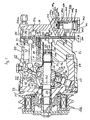
- Figure 1 is a vertical longitudinal sectional view of a slant plate type refrigerant compressor including a capacity control mechanism according to a first embodiment of the invention.
- Figure 2 is an enlarged partial sectional view of the capacity control mechanism shown in Figure 1.
- Figure 3 is a graph showing the relationship between the amperage of an electric supplied from an electric circuit to an electromagnetic coil and the corresponding suction chamber pressure at which the upward and downward forces acting on a diaphragm are balanced.
- Figure 4 is a graph showing the changes in pressure differential between the crank and suction chambers over a period of time after the supply of electric current having a predetermined maximum amperage from an electric circuit to an electromagnetic coil is initiated.
- Figure 5 is a vertical longitudinal sectional view of a slant plate type refrigerant compressor including a capacity control mechanism according to a second embodiment of this invention.
- Figure 6 is an enlarged partial sectional view of the capacity control mechanism shown in Figure 5.
- Compressor 10 includes cylindrical housing assembly 20 including cylinder block 21, front end plate 23 disposed at one end of cylinder block 21, crank chamber 22 enclosed within cylinder block 21 by front end plate 23, and rear end plate 24 attached to the other end of cylinder block 21.
- Front end plate 23 is mounted on cylinder block 21 forward of crank chamber 22 by a plurality of bolts 101.
- Rear end plate 24 is also mounted on cylinder block 21 at the opposite end by a plurality of bolts (not shown).
- Valve plate 25 is located between rear end plate 24 and cylinder block 21.
- Opening 231 is centrally formed in front end plate 23 for supporting drive shaft 26 by bearing 30 disposed therein.
- the inner end portion of drive shaft 26 is rotatably supported by bearing 31 disposed within central bore 210 of cylinder block 21. Bore 210 extends to a rear end surface of cylinder block 21.
- Bore 210 includes thread portion 211 formed at an Inner peripheral surface of a central region thereof. Adjusting screw 220 having a hexagonal central hole 221 is screwed into thread portion 211 of bore 210. Circular disc-shaped spacer 230 having central hole 259 is disposed between the inner end surface of drive shaft 26 and adjusting screw 220. Axial movement of adjusting screw 220 is transferred to drive shaft 26 through spacer 230 so that all three elements move axially within bore 210.
- the above-mentioned construction and functional manner are described in detail in US-A-4,948,343.
- Cam rotor 40 is fixed on drive shaft 26 by pin member 261 and rotates with drive shaft 26.
- Thrust needle bearing 32 is disposed between the inner end surface of front end plate 23 and the adjacent axial end surface of cam rotor 40.
- Cam rotor 40 includes arm 41 having pin member 42 extending therefrom.
- Slant plate 50 is disposed adjacent cam rotor 40 and includes opening 53.
- Drive shaft 26 is disposed through opening 53.
- Slant plate 50 includes arm 51 having slot 52.
- Cam rotor 40 and slant plate 50 are connected by pin member 42, which is Inserted in slot 52 to create a hinged joint.
- Pin member 42 is slldable within slot 52 to allow adjustment of the angular position of slant plate 50 with respect to a plane perpendicular to the longitudinal axis of drive shaft 26.
- a balance weight ring 80 having a substantial mass is disposed on a nose of hub 54 of slant plate 50 in order to balance the slant plate 50 under dynamic operating conditions. Balance weight ring 80 held in place by means of retaining ring 81.
- Wobble plate 60 is nutatably mounted on hub 54 of slant plate 50 through bearings 61 and 62 which allow slant plate 50 to rotate with respect to wobble plate 60.
- Fork-shaped slider 63 is attached to the radially outer peripheral end of wobble plate 60 and is slldably mounted about sliding rail 64 disposed between front end plate 23 and cylinder block 21. Fork-shaped slider 63 prevents the rotation of wobble plate 60 such that wobble plate 60 nutates along rail 64 when cam rotor 40, slant plate 50 and balance weight ring 80 rotate.
- Cylinder block 21 includes a plurality of peripherally located cylinder chambers 70 in which pistons 71 are disposed. Each piston 71 is connected to wobble plate 60 by a corresponding connecting rod 72. Accordingly, nutation of wobble plate 60 thereby causes pistons 71 to reciprocate within their respective chambers 70.
- Rear end plate 24 includes peripherally located annular auction chamber 241 and centrally located discharge chamber 251.
- Valve plate 25 includes a plurality of valve suction ports 242 linking suction chamber 241 with respective cylinders 70.
- Valve plate 25 also includes a plurality of valved discharge ports 252 linking charge chamber 251 with respective cylinders 70. Suction ports 242 and discharge ports 252 are provided win suitable reed valves as described in U.S. Patent No. 4,011,029 to Shimizu.
- Suction chamber 241 includes inlet portion 241a which is connected to an evaporator (not shown) of the external cooling circuit.
- Discharge chamber 251 is provided with outlet portion 251a connected to a condenser (not shown) of the cooling circuit.
- Gaskets 27 and 28 are located between cylinder block 21 and the inner surface of valve plate 25 and between the outer surface of valve plate 25 and rear end plate 24, respectively, to seal the mating surfaces of cylinder block 21, valve plate 25 and rear end plate 24. Gaskets 27 and 28 and valve plate 25 thus form valve plate assembly 200.
- a steel valve retainer 253 is fixed on a central region of the outer surface of valve plate 25 by bolt 254 and nut 255. Valve retainer 253 prevents excessive bend of the reed valve which is provided at discharge port 252 during a compression stroke of piston 71.
- Conduit 18 is axially bored through cylinder block 21 so as to link crank chamber 22 to discharge chamber 251 through hole 181 which is axially bored through valve plate assembly 200.
- a throttling device such as orifice tube 182, is fixedly disposed within conduit 18.
- Filter member 183 is disposed in conduit 18 at the rear of orifice tube 182. Accordingly, a portion of the discharged refrigerant gas in discharge chamber 251 always flows into crank chamber 22 with a reduced pressure generated by orifice tube 182.
- Rear end plate 24 further includes bulged portion 243 radially extending from a central region to a radial end thereof. Cylindrical cavity 244 is formed in bulged portion 243 so as to accommodate capacity control mechanism 400 which is further discussed below.
- One end or cavity 244 is open to the external environment outside of the compressor, that is, to atmospheric conditions.
- cylindrical cavity 244 includes large, intermediate, and small diameter portions 244a, 244b and 244c, respectively, which thereby from an axial outer end thereof.
- the diameter of intermediate diameter portion 244b is smaller than the diameter of large diameter portion 244a, and is greater than the diameter of small diameter portion 244c.
- Large diameter portion 244a is linked to Intermediate diameter portion 244b through truncated cone portion 244d, Large diameter portion 244a of cavity 244 is linked to suction chamber 241 through conduit 245 which is formed in rear end plate 24.
- Conduit 246 is also formed in rear end plate 24 so as to link small diameter portion 244c of cavity 244 to hole 256 which is formed in valve plate assembly 200.
- Hole 256 is linked to central bore 210 through conduit 212 which is formed in the rear portion of cylinder block 21.
- Central bore 210 is linked to crank chamber 22 through gap 31a created between bearing 31 and the inner peripheral surface of central bore 210, hole 231 of spacer 230 and hole 221 of adjusting screw 220. Accordingly, small diameter portion 244c of cavity 244 is linked to crank chamber 22 via conduit 246, hole 256, conduit 212, central bore 210, hole 221, hole 231 and gap 31a.
- Capacity control mechanism 400 includes a first annular cylindrical casing 410 of magnetic material accommodated in large diameter portion 244a of cavity 244 and a second annular cylindrical casing 420 having a large diameter section 421 and a small diameter section 422 which extends upwardly from a top end of large diameter section 421.
- Large diameter section 421 of second annular cylindrical casing 420 is fixedly disposed at a top end of first annular cylindrical casing 410.
- the top end of small diameter section 422 of second annular cylindrical casing 420 terminates at a point approximately half the lenght of small diameter portion 244c of cavity 244.
- Annular protrusion 423 is formed at a boundary between large and small diameter sections 421 and 422 of second annular cylindrical casing 420, and is disposed within intermediate diameter portion 244b of cavity 244.
- An O-ring seal element 423a is disposed in an annular groove 423b formed at the outer peripheral surface of annular protrusion 423 so as to seal the mating surfaces between the outer peripheral surface of annular protrusion 423 and the inner peripheral surface of intermediate diameter portion 244b of cavity 244.
- small diameter portion 244c of cavity 244 is sealingly insulated from large diameter portion 244a of cavity 244.
- First annular cylindrical casing 410 includes an annular flange 411, which radially and inwardly extends from the top portion of first annular cylindrical casing 410, and an axial annular projection 412 which axially and downwardly extends from an inner peripheral end portion of annular flange 411.
- Axial annular projection 412 terminates at a point approximately one-third of the length of first annular cylindrical casing 410, and includes a tapered bottom end surface 412a.
- Cylindrical pipe member 413 the length of which is a little less than the length of first annular cylindrical casing 410, is disposed in first annular cylindrical casing 410.
- annular pipe member 413 An upper end portion of cylindrical pipe member 413 is fixedly attached to the outer peripheral surface of axial annular projection 412 by forcible insertion.
- Annular disc plate 414 is fixedly disposed at a bottom end of first annular cylindrical casing 410 to define an annular cavity 415 formed in cooperation with cylindrical pipe member 413 and first annular cylindrical casing 410.
- Electromagnetic coil 430 is fixedly disposed within annular cavity 415.
- Annular cylindrical pedestal 440 is disposed at the bottom portion of cylindrical pipe member 413. The upper half portion of pedestal 440 is fixedly attached to an inner peripheral surface of the bottom portion of cylindrical pipe member 413 by forcible insertion.
- a vacant space 450 is defined by cylindrical pipe member 413, annular cylindrical pedestal 440 and axial annular projection 412 of first annular cylindrical casing 410.
- Cylindrical member 451 of magnetic material is axially and movably disposed in vacant space 450.
- Cylindrical rod 460 having circular disc plate 461 at its top end loosely penetrates through axial annular projection 412. The bottom end portion of rod 460 is fixedly received in cylindrical hole 451a formed in the tog end surface of cylindrical member 451 through forcible insertion.
- Cylindrical member 451 includes tapered top end surface 451b which is parallel to the tapered bottom end surface 412a of axial annular projection 412.
- Annular cylindrical pedestal 440 includes a thread portion 441 formed in the inner peripheral surface of the lower half portion thereof. Adjusting screw 442 is screwed into thread portion 441 formed in the inner peripheral surface of the lower half of annular cylindrical pedestal 440.
- First coil spring 470 is disposed between adjusting screw 442 and the top end surface of cylindrical hole 451c which is formed at the bottom end surface of cylindrical member 451. The restoring force of first coil spring 470 urges cylindrical member 451 upwardly, thereby urging rod 460 upwardly. The restoring force of first coil spring 470 is adjusted by changing in the axial position of ajusting screw 442.
- electromagnetic coil 430 When electromagnetic coil 430 is energized, an electromagnetic force which tends to move cylindrical member 451 upwardly is induced.
- the magnitude of the electromagnetic force is directly proportional to the amperage of an electric current that is supplied to electromagnetic coil 430 from an electric circuit (not shown).
- the electric circuit receives a signal representing the heat load on the evaporator, such as the temperature of air immediately before passing through the evaporator, and the signal representing the amount of demand for acceleration of the automobile, such as the magnitude of force stepping on the accelerator.
- an electric current After processing the two signals, an electric current is supplied from the electric circuit to electromagnetic coil 430 in response to changes in the values of the two signals.
- the amperage of the electric current is continuously varied within the range from zero ampere to a predetermined maximum amperage, for example, 1.0 ampere.
- an electric current having the predetermined maximum amperage is supplied from the electric circuit to the electromagnetic coil 430 even though the heat load on the evaporator is excessively large. Furthermore, when the heat load on the evaporator is excessively small, such as when the temperature of air immediately before passing through the evaporator is excessively low, an electric current having the predetermined maximum amperage is supplied from the electric circuit to the electromagnetic coil 430 without regard to the amount of demand for acceleration of the automobile.
- O-ring seal element 416 is disposed in annular groove 417 formed in the outer peripheral surface of the bottom end portion of first annular cylindrical casing 410, to thereby seal the mating surfaces between the outer peripheral surface of first annular cylindrical casing 410 and the inner peripheral surface of large diameter portion 244a of cavity 244.
- large diameter portion 244a of cavity 244 is sealingly insulated from the ambient atmosphere outside of the compressor.
- Snap ring 431 is fixedly disposed at the bottom end of the inner peripheral surface of cavity 244 so as to prevent capacity control mechanism 400 from failing out of cavity 244.
- Valve member 480 is disposed in the inner space of large diameter section 421 of second annular cylindrical casing 420.
- First axial hole 481 is centrally formed in valve member 480 and is open through to the bottom end of valve member 480.
- Valve member 480 is provided with circular plate 482 fixedly disposed at the bottom end thereof so as to close the bottom opening of first axial hole 481.
- First axial hole 481 terminates after extending approximately two-thirds of thy length through valve member 480. The diameter of the terminal end portion of first axial hole 481 gradually decreases upwardly to form a valve seat 483.
- Second axial hole 484 having a diameter smaller than the diameter of first axial hole 481, is centrally formed in the top portion of valve member 480 so as to link first axial hole 481 to the interior space of small diameter section 422 of second annular cylindrical casing 420.
- Ball member 485a is elastically supported by a second coil spring 485b, the bottom end thereof being disposed at circular plate 482 such that ball member 485a is urged upwardly by virtue of the restoring force of second coil spring 485b.
- ball member 485a and second coil spring 485b substantially form safety valve device 485, as further discussed below.
- Valve member 480 includes a truncated cone portion 487 formed at the top end thereof.
- Radial hole 488 is formed in a side wall of valve member 480 so as to link the inner space of large diameter section 421 of second annular cylindrical casing 420 to first axial hole 481 of valve member 480.
- a plurality of radial holes 424 are formed in large diameter section 421 of second annular cylindrical casing 420 so as to link large diameter portion 244a of cavity 244 to the interior region of large diameter section 421 of second annular cylindrical casing 420.
- First annular ridge 489 is formed in the inner peripheral surface of annular casing 420 at the boundary between large and small diameter sections 421 and 422 of annular casing 420.
- First annular ridge 489 functions as a valve seat which truncated cone portion 487 of valve member 480 contacts.
- Second annular ridge 490 is formed in a top portion of the inner peripheral surface of small diameter section 422 of annular casing 420 by reducing the inner diameter thereof.
- Third coil spring 491 is disposed within the inner space of small diameter section 422. The top end of third coil spring 491 contacts second annular ridge 490 and the bottom end of third coil spring 491 contacts the flat top surface of valve member 480. Therefore, valve member 480 is urged downwardly by the restoring force of third coil spring 491.
- a plurality of radial holes 492 are formed in small diameter section 422 of second annular cylindrical casing 420 so as to link small diameter portion 244c of cavity 224 to the interior region of small diameter section 422 of second annular
- Diaphragm 418 is disposed between disc plate 461 of rod 460 and circular plate 482 of valve member 480.
- the top surface of the central region of diaphragm 418 is maintained in contact with the bottom surface of circular plate 482 of valve member 480 by virtue of the restoring force of third coil spring 491.
- the bottom surface of the central region of diaphragm 418 is maintained in contact with the top surface of disc plate 461 of rod 460 by virtue of the restoring of first coil spring 470.
- diaphragm 418 An outer peripheral portion of diaphragm 418 is sandwiched between annular flange 411 of first annular cylindrical casing 410 and flange 425 which radially and outwardly extends from the bottom end of second annular cylindrical casing 420.
- O-ring seal element 419 is disposed between the top end surface of flange 411 of casing 410 and the bottom end surface of the outer peripheral portion of diaphragm 418 to thereby effectively seal the mating surfaces therebetween.
- Indent 411a is formed at the top end surface of the inner peripheral portion of annular flange 411 of casing 410 such that indent 411a faces the bottom end surface of diaphragm 418.
- Indent 411a is linked to the ambient atmosphere outside of the compressor via the gap 412b created between rod 460 and annular projection 412, vacant space 450, the gap 440a created between pedestal 440 and pipe member 413, and the gap 440b created between pedestal 440 and adjusting screw 442.
- the bottom end surface of diaphragm 418 is in communication with and thereby receives air at atmospheric pressure.
- the interior region of the large diameter section 421 of second casing 420 is linked to suction chamber 241 via holes 424, large diameter portion 244a of Cavity 244, and conduit 245.
- the top end surface of diaphragm 418 is in communication with and thereby receives the refrigerant at the suction chamber pressure.
- drive shaft 26 is rotated by the engine of the automobile through electromagnetic clutch 300.
- Cam rotor 40 is rotated with drive shaft 26, thereby rotating slant plate 50 as well, which in turn causes wobble plate 60 to nutate.
- the nutational motion of wobble plate 60 then reciprocates pistons 71 in their respective cylinders 70.
- refrigerant gas is introduced into suction chamber 241 through inlet portion 241a, flows into each cylinder 70 through suction ports 242, and is then compressed.
- the compressed refrigerant gas is then discharged to discharge chamber 251 from each cylinder 70 through discharge ports 252, and continues therefrom into the cooling circuit through outlet portion 251a.
- the capacity of compressor 10 is adjusted in order to maintain a constant pressure in suction chamber 241, irrespective of the changes in the heat load on the evaporator or the rotating speed of the compressor.
- the capacity of the compressor is adjusted by changing the angle of the slant plate, which is dependent upon the crank chamber pressure, or more precisely, which is dependent upon the differential between the crank chamber and the suction chamber pressures.
- the pressure of the crank chamber increases due to blow-by gas flowing past pistons 71 as they reciprocate in cylinders 70.
- the slant angle of slant plate 50 as well as the slant angle of wobble plate 60 decrease, thereby decreasing the capacity of the compressor.
- a decrease in the crank chamber pressure relative to the suction chamber pressure causes an increase in the angle of slant plate 50 and wobble plate 60, and thus an increase in the capacity of the compressor.
- capacity control mechanism 400 of compressor 10 in accordance with the first embodiment of the present invention is carried out in the following manner.
- the heat load on the evaporator is excessively large and concurrently therewith the amount of demand for acceleration of the automobile is small, no electric current is supplied from the electric circuit to the electromagnetic coil 430.
- diaphragm 118 is urged upwardly only by virtue of the restoring force of first coil spring 470 and the atmospheric pressure force acting on the bottom end surface of diaphragm 418.
- valve member 480 is situated so as to maintain an opening for communication between small diameter portion 244c of cavity 244 and large diameter portion 244a of cavity 244.
- Valve member 480 maintains such a position until the suction chamber pressure drops to a first predetermined value, for example 1.0 kg/cm2 G, at which time the upward and downward forces acting on diaphragm 418 will be balanced.
- a first predetermined value for example 1.0 kg/cm2 G
- slant plate 50 and wobble plate 60 are disposed at a maximum slant angle with respect to the plane perpendicular to the longitudinal axis of drive shaft 26 due to an opening for fluid communication between crank chamber 22 and suction chamber 241; and accordingly, compressor 10 operates in a maximum capacity displacement until the suction chamber pressure drops to the first predetermined value.
- the slant angle of slant plate 50 and wobble plate 60 is adjusted in response to the changes in the heat load on the evaporator in order to thereby maintain the suction chamber pressure at the first predetermined value.
- Valve member 480 maintains such a portion until the suction chamber pressure rises to a second predetermined value, for example 4,0 kg/cm2G, at which time the upward and downward forces acting on diaphragm 418 are balanced. Therefore, slant plate 50 and wobble plate 60 are disposed at a minimum slant angle with respect to the plane perpendicular to the longitudinal axis of drive shaft 26 due to the block in fluid communication between crank chamber 22 and suction chamber 241; and accordingly, compressor 10 operates at a minimum capacity displacement until the suction chamber pressure rises to the second predetermined value.
- a second predetermined value for example 4,0 kg/cm2G
- the slant angle of slant plate 50 and wobble plate 60 is adjusted in response to the changes in the heat load on the evaporator in order to thereby maintain the suction chamber pressure at the second predetermined value.
- the location of valve member 480 is likewise continuously varied in response to these amperage changes. Therefore, as shown in Figure 3, the suction chamber pressure at which the upward and downward forces acting on diaphragm 418 are balanced is also continuously varied within the range defined by the first and second predetermined values.
- the angular position of slant plate 50 and wobble plate 60 is continuously varied within a range defined by the maximum and minimum slant angles and the capacity displacement of compressor 10 is similarly varied within a range defined by the maximum and the minimum values thereof.
- the capacity displacement of compressor 10 is adjusted to maintain a predetermined constant pressure in suction chamber 241.
- the angular position of slant plate 50 and wobble plate 60 is forcibly changed to, and then is maintained at the minimum slant angle until the suction chamber pressure rises to the second predetermined value, i.e., 4.0 kg/cm2 G.
- valve member 480 is forcibly moved and then maintained so as to close the fluid communication opening between small diameter portion 244c of cavity 244 and large diameter portion 244a of cavity 244, until such a time that the suction chamber pressure rises to the second predetermined value, i.e., 4.0 kg/cm2 G.
- Safety valve device 485 includes ball member 485a and second coil spring 485b which elastically supports ball member 485a.
- Safety valve device 485 functions in the following manner. Ball member 485a is urged downwardly by the crank chamber pressure received on the upper spherical surface thereof while also being urged upwardly by the restoring force of second coil spring 485b and the suction chamber pressure received on the lower spherical surface thereof.
- Safety valve device 485 is designed so as to open second axial hole 484 when the pressure differential between crank chamber 22 and suction chamber 241 rises to a predetermined value, for example, 2.0 kg/cm2.
- crank chamber pressure is forcibly and quickly reduced so as to maintain the pressure differential between crank chamber 22 and suction chamber 241 at the predetermined value, i.e., 2.0 kg/cm2, as shown by the solid line in Figure 4, and thereby maintain the angular position of slant plate 50 and wobble plate 60 at the minimum slant angle even when the amperage of the electric current is suddenly increased from zero ampere to the predetermined maximum amperage.
- safety valve device 486 functions equally as well when the fluid communication opening between crank chamber 22 and suction chamber 241 is blocked for a long time period due to problems with the movement of valve member 480.
- capacity control mechanism 400 is provided with safety valve device 485 therein, the complicated process of forming an additional passageway for communicating crank chamber 22 with suction chamber 241 in cylinder block 21 and the process of disposing the safety valve device in the additional passageway, are thus eliminated. Therefore, according to the present invention, a compressor having an externally controlled capacity control mechanism and a safety valve device for preventing an abnormal pressure differential between the crank and suction chambers can be easily manufactured.
- a wobble plate type refrigerant compressor including a capacity control mechanism in accordance with a second embodiment of the present invention is shown. As illustrated, like reference numerals are used to denote like elements corresponding to those shown in Figures 1 and 2. Except where otherwise stated, the overall functioning of the compressor is the same as discussed above.
- capacity control mechanism 500 of the wobble plate type refrigerant compressor includes a valve member 580 disposed in the interior region of large diameter section 421 of second annular cylindrical casing 420.
- First axial hole 581 is centrally formed in valve member 580, and is open through to the top end of valve member 580.
- First axial hole 581 terminates at a point corresponding to half of the length of valve member 580.
- the diameter of the terminal end portion of first axial hole 581 is gradually decreased downward so as to form a valve seat 582.
- Second axial hole 583 having a diameter smaller than the diameter of first axial hole 581, extends from the terminal end of first axial hole 581 to the bottom end portion of valve member 580.
- Ball member 584a is disposed in valve seat 582.
- Annular ring member 585 through which valve member 580 slidably moves along the longitudinal axis, is fixedly disposed at the inner peripheral surface of large diameter section 421 of second annular cylindrical casing 420 by forcible insertion.
- Valve member 580 includes a truncated cone portion 586 formed at the top end thereof. The inner space of large diameter section 421 of second annular cylindrical casing 420 is linked to second axial hole 583 of valve member 580 through radial hole 488.
- Third coil spring 587 is elastically disposed between truncated cone portion 586 of valve member 580 and an annular ridge 588 which is formed at the inner peripheral surface of the boundary region between large and small diameter sections 421 and 422 of second annular cylindrical casing 420. Valve member 580 is urged downwardly by virtue of the restoring force of third coil spring 587.
- Second annular cylindrical casing 420 further includes a thread portion 589 formed at the inner peripheral surface of the top end portion thereof. Adjusting screw 590 is screwed into thread portion 589 of second annular cylindrical casing 420. Axial hole 590a is formed through ajusting screw 590 so as to link small diameter portion 244c of cavity 244 to the interior region of small diameter section 422 of second annular cylindrical casing 420. Second coil spring 584b is disposed between adjusting screw 590 and an upper spherical surface of ball member 584a so as to urge ball member 584a downwardly by virtue of the restoring force of second coil spring 584b. The restoring force of second coil spring 584b is adjusted by the changes in the axial position of adjusting screw 590. Ball member 584a and second coil spring 584b substantially form safety valve device 584.
- Conduit 247 is formed in rear end plate 24 so as to link small diameter portion 244c of cavity 244 to suction chamber 241.
- Conduit 248 is also formed in rear end plate 24 so as to link large diameter portion 244a of cavity 244 to hole 256.
- the interior region of the large diameter section 421 of second casing 420 is linked to crank chamber 22 via holes 424, large diameter portion 244a of cavity 244, conduit 248, hole 256, conduit 212, central bore 210, hole 221, hole 231 and gap 31a.
- the top end surface of diaphragm 418 is in communication with and thereby receives the refrigerant at the crank chamber pressure. Accordingly, the capacity of compressor 10 is adjusted to maintain a predetermined constant pressure in crank chamber 22, which in turn, also maintains a predetermined constant pressure in suction chamber 241, eventually.
Description
- The present invention relates to a refrigerant compressor, and more particularly, to a slant plate type compressor, such as a wobble plate type compressor, having a variable displacement mechanism which is suitable for use in an automobile air conditioning system.
- Slant plate type piston compressors including variable displacement or capacity adjusting mechanisms for controlling the compression ratio of a compressor in response to demand are generally known in the art. For example, JP-U-63-134181 discloses a wobble plate type compressor including a cam rotor driving device and a wobble plate linked to a plurality of pistons. Rotation of the cam rotor driving device causes the wobble plate to nutate and thereby successively reciprocate the pistons in the corresponding cylinders. The stroke length of the pistons and thus the capacity of the compressor may be easily changed by adjusting the slant angle of the wobble plate. The slant angle is changed in response to the pressure differential between the suction chamber and the crank chamber.
- In the above-mentioned Japanese Utility Model Application Publication, the crank chamber and the suction chamber are linked in fluid communication by a first path or passageway. A valve mechanism is disposed in the first passageway in order to control fluid communication between the crank and suction chambers by the opening and closing of the first passageway. The valve mechanism generally includes a solenoid, a plunger and a valve member disposed on one end of the plunger. The solenoid receives two external signals, one of which represents the heat load on an evaporator of a cooling circuit and another which represents the amount of demand for accelerating an automobile.
- The solenoid induces various electromagnetic forces in response to changes in the two external signals and thereby changes the axial position of the plunger so that the first passageway is opened and closed by the valve member. Hence, the angular position of the wobble plate is varied in a range from the maximum to the minimum slant angles responsive to changes in the two external signals such that the capacity displacement of the compressor is thereby adjusted and the suction chamber pressure is maintained at a predetermined constant value.
- The compressor further intrudes a second passageway, separate from the first passageway, and communicating the crank chamber with the suction chamber. A safety valve device including a bail member and a coil spring elastically supporting the ball member is deposed in the second passageway. The safety valve device opens and closes the second passageway in response to change in the pressure differential between the crank chamber and the suction chamber. The second passageway is opened when the pressure differential between the crank chamber and the suction chamber exceeds a predetermined value. Therefore, when communication between the crank chamber and the suction chamber is blocked for a lone time period of time due to trouble in the valve mechanism, thereby causing an abnormal rise in the Crank chamber pressure because of blow-by gas leaking past the pistons in the cylinders as the pistons reciprocate, the second passageway is opened so as to forcibly and quickly reduce the crank chamber pressure and thereby prevent an abnormal pressure differential between the crank and suction chambers. As a result, excessive friction between the internal component parts of the compressor caused by the abnormal differential between the crank chamber and the suction chamber can be prevented.
- In this prior art embodiment, the second passageway is separate from the first passageway such that the process of forming the second passageway and the process of disposing the safety valve device in the second passageway are additional steps required during the manufacturing of the compressor. Accordingly, the manufacturing process of the compressor is complicated by this requirement.
- Therefore, a strong need exists for a compressor having a variable displacement control mechanism which can be easily manufactured and which can prevent an abnormal pressure differential between the crank chamber and the suction chamber.
- According to the present invention, a slant plate type refrigerant compressor having a compressor housing enclosing a crank chamber, a suction chamber and a discharge chamber therein, the compressor housing comprising a cylinder block having a plurality of cylinders formed therethrough, a piston slidably fitted within each of the cylinders, drive means coupled to the pistons for reciprocating the pistons within the cylinders, the drive means including a drive shaft rotatably supported in the housing and coupling means for drivingly coupling the drive shaft to the pistons such that rotary motion of the drive shaft is converted into reciprocating motion of the pistons, the coupling means including a slant plate having a surface disposed at an adjustable inclined angle relative to a plane perpendicular to the drive shaft, the inclined angle of the slant plate being adjustable to vary the stroke length of the pistons in the cylinders and to thereby vary the capacity of the compressor, a passageway formed in the housing and linking the crank chamber and the suction chamber in fluid communication, capacity control means for varying the capacity of the compressor by adjusting the inclined angle, and safety valve means for preventing an abnormal pressure differential between the crank chamber and the suction chamber, the capacity control means including externally controlled valve means for controlling the opening and closing of the passageway in response to changes in a plurality of external signals to control the link between the crank and the suction chambers and to thereby control the capacity of the compressor, the externally controlled valve means being disposed in the passageway, and the safety valve means being so as to open the passageway when the pressure differential between the crank chamber and the suction chamber exceeds a predetermined value; (as disclosed in JP-U-63-134181) is characterised in that the externally controlled valve means includes a valve element which opens and closes the passageway and the safety valve means is disposed within the valve element.
- In the accompanying drawings:
- Figure 1 is a vertical longitudinal sectional view of a slant plate type refrigerant compressor including a capacity control mechanism according to a first embodiment of the invention.
- Figure 2 is an enlarged partial sectional view of the capacity control mechanism shown in Figure 1.
- Figure 3 is a graph showing the relationship between the amperage of an electric supplied from an electric circuit to an electromagnetic coil and the corresponding suction chamber pressure at which the upward and downward forces acting on a diaphragm are balanced.
- Figure 4 is a graph showing the changes in pressure differential between the crank and suction chambers over a period of time after the supply of electric current having a predetermined maximum amperage from an electric circuit to an electromagnetic coil is initiated.
- Figure 5 is a vertical longitudinal sectional view of a slant plate type refrigerant compressor including a capacity control mechanism according to a second embodiment of this invention.
- Figure 6 is an enlarged partial sectional view of the capacity control mechanism shown in Figure 5.
- In Figures 1 and 5, for purpose of explanation only, the left side of the figures will be referenced as the forward end or front of the compressor, and the right side of the figures will be referenced as the rearward end or rear of the compressor.
- With reference to figure 1, the construction of a slant plate type compressor, and more specifically a wobble plate
type refrigerant compressor 10, having a capacity control mechanism in accordance with a first embodiment of the present invention is shown.Compressor 10 includescylindrical housing assembly 20 includingcylinder block 21,front end plate 23 disposed at one end ofcylinder block 21,crank chamber 22 enclosed withincylinder block 21 byfront end plate 23, andrear end plate 24 attached to the other end ofcylinder block 21.Front end plate 23 is mounted oncylinder block 21 forward ofcrank chamber 22 by a plurality ofbolts 101.Rear end plate 24 is also mounted oncylinder block 21 at the opposite end by a plurality of bolts (not shown). Valveplate 25 is located betweenrear end plate 24 andcylinder block 21.Opening 231 is centrally formed infront end plate 23 for supportingdrive shaft 26 by bearing 30 disposed therein. The inner end portion ofdrive shaft 26 is rotatably supported by bearing 31 disposed withincentral bore 210 ofcylinder block 21. Bore 210 extends to a rear end surface ofcylinder block 21. - Bore 210 includes thread portion 211 formed at an Inner peripheral surface of a central region thereof. Adjusting
screw 220 having a hexagonalcentral hole 221 is screwed into thread portion 211 ofbore 210. Circular disc-shaped spacer 230 having central hole 259 is disposed between the inner end surface ofdrive shaft 26 and adjustingscrew 220. Axial movement of adjustingscrew 220 is transferred to driveshaft 26 throughspacer 230 so that all three elements move axially withinbore 210. The above-mentioned construction and functional manner are described in detail in US-A-4,948,343. -
Cam rotor 40 is fixed ondrive shaft 26 bypin member 261 and rotates withdrive shaft 26. Thrust needle bearing 32 is disposed between the inner end surface offront end plate 23 and the adjacent axial end surface ofcam rotor 40.Cam rotor 40 includes arm 41 havingpin member 42 extending therefrom. Slantplate 50 is disposedadjacent cam rotor 40 and includes opening 53.Drive shaft 26 is disposed through opening 53.Slant plate 50 includesarm 51 havingslot 52.Cam rotor 40 andslant plate 50 are connected bypin member 42, which is Inserted inslot 52 to create a hinged joint.Pin member 42 is slldable withinslot 52 to allow adjustment of the angular position ofslant plate 50 with respect to a plane perpendicular to the longitudinal axis ofdrive shaft 26. Abalance weight ring 80 having a substantial mass is disposed on a nose of hub 54 ofslant plate 50 in order to balance theslant plate 50 under dynamic operating conditions.Balance weight ring 80 held in place by means of retainingring 81. - Wobble plate 60 is nutatably mounted on hub 54 of
slant plate 50 throughbearings slant plate 50 to rotate with respect to wobble plate 60. Fork-shaped slider 63 is attached to the radially outer peripheral end of wobble plate 60 and is slldably mounted about slidingrail 64 disposed betweenfront end plate 23 andcylinder block 21. Fork-shaped slider 63 prevents the rotation of wobble plate 60 such that wobble plate 60 nutates alongrail 64 whencam rotor 40,slant plate 50 andbalance weight ring 80 rotate. Undesirable axial movement of wobble plate 60 on hub 54 ofslant plate 50 is prevented by contact between a rear end surface of innerannular projection 65 of wobble plate 60 and a front end surface ofbalance weight ring 80.Cylinder block 21 includes a plurality of peripherally locatedcylinder chambers 70 in whichpistons 71 are disposed. Eachpiston 71 is connected to wobble plate 60 by acorresponding connecting rod 72. Accordingly, nutation of wobble plate 60 thereby causespistons 71 to reciprocate within theirrespective chambers 70. -
Rear end plate 24 includes peripherally locatedannular auction chamber 241 and centrally located discharge chamber 251. Valveplate 25 includes a plurality ofvalve suction ports 242 linkingsuction chamber 241 withrespective cylinders 70. Valveplate 25 also includes a plurality of valveddischarge ports 252 linking charge chamber 251 withrespective cylinders 70.Suction ports 242 anddischarge ports 252 are provided win suitable reed valves as described in U.S. Patent No. 4,011,029 to Shimizu. -
Suction chamber 241 includesinlet portion 241a which is connected to an evaporator (not shown) of the external cooling circuit. Discharge chamber 251 is provided withoutlet portion 251a connected to a condenser (not shown) of the cooling circuit.Gaskets cylinder block 21 and the inner surface ofvalve plate 25 and between the outer surface ofvalve plate 25 andrear end plate 24, respectively, to seal the mating surfaces ofcylinder block 21,valve plate 25 andrear end plate 24.Gaskets valve plate 25 thus formvalve plate assembly 200. Asteel valve retainer 253 is fixed on a central region of the outer surface ofvalve plate 25 by bolt 254 and nut 255.Valve retainer 253 prevents excessive bend of the reed valve which is provided atdischarge port 252 during a compression stroke ofpiston 71. -
Conduit 18 is axially bored throughcylinder block 21 so as to link crankchamber 22 to discharge chamber 251 throughhole 181 which is axially bored throughvalve plate assembly 200. A throttling device such asorifice tube 182, is fixedly disposed withinconduit 18.Filter member 183 is disposed inconduit 18 at the rear oforifice tube 182. Accordingly, a portion of the discharged refrigerant gas in discharge chamber 251 always flows into crankchamber 22 with a reduced pressure generated byorifice tube 182. The above-mentioned construction and functional manner are described in detail in JP-A-1-142277. -
Rear end plate 24 further includes bulgedportion 243 radially extending from a central region to a radial end thereof.Cylindrical cavity 244 is formed in bulgedportion 243 so as to accommodatecapacity control mechanism 400 which is further discussed below. One end orcavity 244 is open to the external environment outside of the compressor, that is, to atmospheric conditions. - With reference to Figure 2 additionally,
cylindrical cavity 244 includes large, intermediate, andsmall diameter portions intermediate diameter portion 244b is smaller than the diameter oflarge diameter portion 244a, and is greater than the diameter of small diameter portion 244c.Large diameter portion 244a is linked toIntermediate diameter portion 244b throughtruncated cone portion 244d,Large diameter portion 244a ofcavity 244 is linked tosuction chamber 241 throughconduit 245 which is formed inrear end plate 24.Conduit 246 is also formed inrear end plate 24 so as to link small diameter portion 244c ofcavity 244 to hole 256 which is formed invalve plate assembly 200.Hole 256 is linked tocentral bore 210 throughconduit 212 which is formed in the rear portion ofcylinder block 21. Central bore 210 is linked to crankchamber 22 through gap 31a created betweenbearing 31 and the inner peripheral surface ofcentral bore 210,hole 231 ofspacer 230 andhole 221 of adjustingscrew 220. Accordingly, small diameter portion 244c ofcavity 244 is linked to crankchamber 22 viaconduit 246,hole 256,conduit 212,central bore 210,hole 221,hole 231 and gap 31a. -
Capacity control mechanism 400 includes a first annularcylindrical casing 410 of magnetic material accommodated inlarge diameter portion 244a ofcavity 244 and a second annularcylindrical casing 420 having alarge diameter section 421 and asmall diameter section 422 which extends upwardly from a top end oflarge diameter section 421.Large diameter section 421 of second annularcylindrical casing 420 is fixedly disposed at a top end of first annularcylindrical casing 410. The top end ofsmall diameter section 422 of second annularcylindrical casing 420 terminates at a point approximately half the lenght of small diameter portion 244c ofcavity 244.Annular protrusion 423 is formed at a boundary between large andsmall diameter sections cylindrical casing 420, and is disposed withinintermediate diameter portion 244b ofcavity 244. An O-ring seal element 423a is disposed in an annular groove 423b formed at the outer peripheral surface ofannular protrusion 423 so as to seal the mating surfaces between the outer peripheral surface ofannular protrusion 423 and the inner peripheral surface ofintermediate diameter portion 244b ofcavity 244. Thus, small diameter portion 244c ofcavity 244 is sealingly insulated fromlarge diameter portion 244a ofcavity 244. - First annular
cylindrical casing 410 includes anannular flange 411, which radially and inwardly extends from the top portion of first annularcylindrical casing 410, and an axialannular projection 412 which axially and downwardly extends from an inner peripheral end portion ofannular flange 411. Axialannular projection 412 terminates at a point approximately one-third of the length of first annularcylindrical casing 410, and includes a taperedbottom end surface 412a.Cylindrical pipe member 413, the length of which is a little less than the length of first annularcylindrical casing 410, is disposed in first annularcylindrical casing 410. An upper end portion ofcylindrical pipe member 413 is fixedly attached to the outer peripheral surface of axialannular projection 412 by forcible insertion.Annular disc plate 414 is fixedly disposed at a bottom end of first annularcylindrical casing 410 to define anannular cavity 415 formed in cooperation withcylindrical pipe member 413 and first annularcylindrical casing 410.Electromagnetic coil 430 is fixedly disposed withinannular cavity 415. Annularcylindrical pedestal 440 is disposed at the bottom portion ofcylindrical pipe member 413. The upper half portion ofpedestal 440 is fixedly attached to an inner peripheral surface of the bottom portion ofcylindrical pipe member 413 by forcible insertion. - A
vacant space 450 is defined bycylindrical pipe member 413, annularcylindrical pedestal 440 and axialannular projection 412 of first annularcylindrical casing 410.Cylindrical member 451 of magnetic material is axially and movably disposed invacant space 450.Cylindrical rod 460 havingcircular disc plate 461 at its top end loosely penetrates through axialannular projection 412. The bottom end portion ofrod 460 is fixedly received incylindrical hole 451a formed in the tog end surface ofcylindrical member 451 through forcible insertion.Cylindrical member 451 includes tapered top end surface 451b which is parallel to the taperedbottom end surface 412a of axialannular projection 412. Annularcylindrical pedestal 440 includes athread portion 441 formed in the inner peripheral surface of the lower half portion thereof. Adjustingscrew 442 is screwed intothread portion 441 formed in the inner peripheral surface of the lower half of annularcylindrical pedestal 440.First coil spring 470 is disposed between adjustingscrew 442 and the top end surface of cylindrical hole 451c which is formed at the bottom end surface ofcylindrical member 451. The restoring force offirst coil spring 470 urgescylindrical member 451 upwardly, thereby urgingrod 460 upwardly. The restoring force offirst coil spring 470 is adjusted by changing in the axial position ofajusting screw 442. - When
electromagnetic coil 430 is energized, an electromagnetic force which tends to movecylindrical member 451 upwardly is induced. The magnitude of the electromagnetic force is directly proportional to the amperage of an electric current that is supplied toelectromagnetic coil 430 from an electric circuit (not shown). The electric circuit receives a signal representing the heat load on the evaporator, such as the temperature of air immediately before passing through the evaporator, and the signal representing the amount of demand for acceleration of the automobile, such as the magnitude of force stepping on the accelerator. After processing the two signals, an electric current is supplied from the electric circuit toelectromagnetic coil 430 in response to changes in the values of the two signals. The amperage of the electric current is continuously varied within the range from zero ampere to a predetermined maximum amperage, for example, 1.0 ampere. - More precisely, when the heat load on the evaporator is excessively large, such that the temperature of air immediately before passing through the evaporator is excessively high, and when the amount of demand for acceleration of the automobile is small, an electric current having zero ampere, i.e., no electric current, is supplied from the electric circuit to the
electromagnetic coil 430 after the processing of the two signals through the electric circuit. However, when the amount of demand for acceleration of the automobile exceeds a predetermined value, the signal representing the demand for acceleration overrides the signal representing the heat load on the evaporator in the processing of the two signals by the electric circuit. As a result, an electric current having the predetermined maximum amperage is supplied from the electric circuit to theelectromagnetic coil 430 even though the heat load on the evaporator is excessively large. Furthermore, when the heat load on the evaporator is excessively small, such as when the temperature of air immediately before passing through the evaporator is excessively low, an electric current having the predetermined maximum amperage is supplied from the electric circuit to theelectromagnetic coil 430 without regard to the amount of demand for acceleration of the automobile. - O-
ring seal element 416 is disposed inannular groove 417 formed in the outer peripheral surface of the bottom end portion of first annularcylindrical casing 410, to thereby seal the mating surfaces between the outer peripheral surface of first annularcylindrical casing 410 and the inner peripheral surface oflarge diameter portion 244a ofcavity 244. Thus,large diameter portion 244a ofcavity 244 is sealingly insulated from the ambient atmosphere outside of the compressor.Snap ring 431 is fixedly disposed at the bottom end of the inner peripheral surface ofcavity 244 so as to preventcapacity control mechanism 400 from failing out ofcavity 244. -
Valve member 480 is disposed in the inner space oflarge diameter section 421 of second annularcylindrical casing 420. Firstaxial hole 481 is centrally formed invalve member 480 and is open through to the bottom end ofvalve member 480.Valve member 480 is provided withcircular plate 482 fixedly disposed at the bottom end thereof so as to close the bottom opening of firstaxial hole 481. Firstaxial hole 481 terminates after extending approximately two-thirds of thy length throughvalve member 480. The diameter of the terminal end portion of firstaxial hole 481 gradually decreases upwardly to form avalve seat 483. Secondaxial hole 484 having a diameter smaller than the diameter of firstaxial hole 481, is centrally formed in the top portion ofvalve member 480 so as to link firstaxial hole 481 to the interior space ofsmall diameter section 422 of second annularcylindrical casing 420. Ball member 485a is elastically supported by asecond coil spring 485b, the bottom end thereof being disposed atcircular plate 482 such that ball member 485a is urged upwardly by virtue of the restoring force ofsecond coil spring 485b. In a preferred embodiment of the invention, ball member 485a andsecond coil spring 485b substantially formsafety valve device 485, as further discussed below.Annular ring member 486, through whichvalve member 480 slidably moves in the axial direction is fixedly disposed at the inner peripheral surface oflarge diameter section 421 of second annularcylindrical casing 420 by forcible insertion.Valve member 480 includes atruncated cone portion 487 formed at the top end thereof.Radial hole 488 is formed in a side wall ofvalve member 480 so as to link the inner space oflarge diameter section 421 of second annularcylindrical casing 420 to firstaxial hole 481 ofvalve member 480. A plurality ofradial holes 424 are formed inlarge diameter section 421 of second annularcylindrical casing 420 so as to linklarge diameter portion 244a ofcavity 244 to the interior region oflarge diameter section 421 of second annularcylindrical casing 420. - First
annular ridge 489 is formed in the inner peripheral surface ofannular casing 420 at the boundary between large andsmall diameter sections annular casing 420. Firstannular ridge 489 functions as a valve seat which truncatedcone portion 487 ofvalve member 480 contacts. Secondannular ridge 490 is formed in a top portion of the inner peripheral surface ofsmall diameter section 422 ofannular casing 420 by reducing the inner diameter thereof.Third coil spring 491 is disposed within the inner space ofsmall diameter section 422. The top end ofthird coil spring 491 contacts secondannular ridge 490 and the bottom end ofthird coil spring 491 contacts the flat top surface ofvalve member 480. Therefore,valve member 480 is urged downwardly by the restoring force ofthird coil spring 491. A plurality ofradial holes 492 are formed insmall diameter section 422 of second annularcylindrical casing 420 so as to link small diameter portion 244c of cavity 224 to the interior region ofsmall diameter section 422 of second annularcylindrical casing 420. -
Diaphragm 418 is disposed betweendisc plate 461 ofrod 460 andcircular plate 482 ofvalve member 480. The top surface of the central region ofdiaphragm 418 is maintained in contact with the bottom surface ofcircular plate 482 ofvalve member 480 by virtue of the restoring force ofthird coil spring 491. Similarly, the bottom surface of the central region ofdiaphragm 418 is maintained in contact with the top surface ofdisc plate 461 ofrod 460 by virtue of the restoring offirst coil spring 470. - An outer peripheral portion of
diaphragm 418 is sandwiched betweenannular flange 411 of first annularcylindrical casing 410 andflange 425 which radially and outwardly extends from the bottom end of second annularcylindrical casing 420. O-ring seal element 419 is disposed between the top end surface offlange 411 ofcasing 410 and the bottom end surface of the outer peripheral portion ofdiaphragm 418 to thereby effectively seal the mating surfaces therebetween. -
Indent 411a is formed at the top end surface of the inner peripheral portion ofannular flange 411 ofcasing 410 such thatindent 411a faces the bottom end surface ofdiaphragm 418.Indent 411a is linked to the ambient atmosphere outside of the compressor via the gap 412b created betweenrod 460 andannular projection 412,vacant space 450, thegap 440a created betweenpedestal 440 andpipe member 413, and the gap 440b created betweenpedestal 440 and adjustingscrew 442. Thus, the bottom end surface ofdiaphragm 418 is in communication with and thereby receives air at atmospheric pressure. - Simillarly, the interior region of the
large diameter section 421 ofsecond casing 420 is linked tosuction chamber 241 viaholes 424,large diameter portion 244a ofCavity 244, andconduit 245. Thus, the top end surface ofdiaphragm 418 is in communication with and thereby receives the refrigerant at the suction chamber pressure. - During operation of
compressor 10,drive shaft 26 is rotated by the engine of the automobile throughelectromagnetic clutch 300.Cam rotor 40 is rotated withdrive shaft 26, thereby rotatingslant plate 50 as well, which in turn causes wobble plate 60 to nutate. The nutational motion of wobble plate 60 then reciprocatespistons 71 in theirrespective cylinders 70. Aspistons 71 are reciprocated, refrigerant gas is introduced intosuction chamber 241 throughinlet portion 241a, flows into eachcylinder 70 throughsuction ports 242, and is then compressed. The compressed refrigerant gas is then discharged to discharge chamber 251 from eachcylinder 70 throughdischarge ports 252, and continues therefrom into the cooling circuit throughoutlet portion 251a. - The capacity of
compressor 10 is adjusted in order to maintain a constant pressure insuction chamber 241, irrespective of the changes in the heat load on the evaporator or the rotating speed of the compressor. The capacity of the compressor is adjusted by changing the angle of the slant plate, which is dependent upon the crank chamber pressure, or more precisely, which is dependent upon the differential between the crank chamber and the suction chamber pressures. During the operation ofcompressor 10, the pressure of the crank chamber increases due to blow-by gas flowingpast pistons 71 as they reciprocate incylinders 70. As the crank chamber pressure increases relative to the suction chamber pressure, the slant angle ofslant plate 50 as well as the slant angle of wobble plate 60 decrease, thereby decreasing the capacity of the compressor. Likewise, a decrease in the crank chamber pressure relative to the suction chamber pressure causes an increase in the angle ofslant plate 50 and wobble plate 60, and thus an increase in the capacity of the compressor. - The operation of
capacity control mechanism 400 ofcompressor 10 in accordance with the first embodiment of the present invention is carried out in the following manner. With reference to Figures 1-3, when the heat load on the evaporator is excessively large and concurrently therewith the amount of demand for acceleration of the automobile is small, no electric current is supplied from the electric circuit to theelectromagnetic coil 430. As a result, diaphragm 118 is urged upwardly only by virtue of the restoring force offirst coil spring 470 and the atmospheric pressure force acting on the bottom end surface ofdiaphragm 418. Under such conditions,valve member 480 is situated so as to maintain an opening for communication between small diameter portion 244c ofcavity 244 andlarge diameter portion 244a ofcavity 244.Valve member 480 maintains such a position until the suction chamber pressure drops to a first predetermined value, for example 1.0 kg/cm² G, at which time the upward and downward forces acting ondiaphragm 418 will be balanced. Thus,slant plate 50 and wobble plate 60 are disposed at a maximum slant angle with respect to the plane perpendicular to the longitudinal axis ofdrive shaft 26 due to an opening for fluid communication between crankchamber 22 andsuction chamber 241; and accordingly,compressor 10 operates in a maximum capacity displacement until the suction chamber pressure drops to the first predetermined value. Once the suction chamber pressure drops to the first predetermined value, the slant angle ofslant plate 50 and wobble plate 60 is adjusted in response to the changes in the heat load on the evaporator in order to thereby maintain the suction chamber pressure at the first predetermined value. - On the other hand, when the heat load on the evaporator is excessively small, an electric current having a predetermined maximum amperage is supplied from the electric circuit to the
electromagnetic coil 430 without regard to the amount of demand for acceleration of the automobile. As a result,diaphragm 418 is urged upwardly by virtue of the restoring force offirst coil spring 470, a predetermined maximum electromagnetic force induced byelectromagnetic coil 430, and the atmospheric pressure force acting on the bottom end surface ofdiaphragm 418.Valve member 480 thus moves upwardly so as to close the fluid communication opening between small diameter portion 244c ofcavity 244 andlarge diameter portion 244a ofcavity 244.Valve member 480 maintains such a portion until the suction chamber pressure rises to a second predetermined value, for example 4,0 kg/cm²G, at which time the upward and downward forces acting ondiaphragm 418 are balanced. Therefore,slant plate 50 and wobble plate 60 are disposed at a minimum slant angle with respect to the plane perpendicular to the longitudinal axis ofdrive shaft 26 due to the block in fluid communication between crankchamber 22 andsuction chamber 241; and accordingly,compressor 10 operates at a minimum capacity displacement until the suction chamber pressure rises to the second predetermined value. Once the suction chamber pressure rises to the second predetermined value, the slant angle ofslant plate 50 and wobble plate 60 is adjusted in response to the changes in the heat load on the evaporator in order to thereby maintain the suction chamber pressure at the second predetermined value. - Furthermore, since the amperage of the electric current supplied from the electric circuit to
electromagnetic coil 430 is continuously varied within the range from zero to the predetermined maximum value in response to the changes in the value of the aforementioned two signals, the location ofvalve member 480 is likewise continuously varied in response to these amperage changes. Therefore, as shown in Figure 3, the suction chamber pressure at which the upward and downward forces acting ondiaphragm 418 are balanced is also continuously varied within the range defined by the first and second predetermined values. Thus, the angular position ofslant plate 50 and wobble plate 60 is continuously varied within a range defined by the maximum and minimum slant angles and the capacity displacement ofcompressor 10 is similarly varied within a range defined by the maximum and the minimum values thereof. - According to the above-mentioned manner of operation for
capacity control mechanism 400, the capacity displacement ofcompressor 10 is adjusted to maintain a predetermined constant pressure insuction chamber 241. - Furthermore, when the demand for acceleration of the automobile exceeds the predetermined value at a time when the suction chamber pressure is being maintained at the first predetermined value, i.e., 1.0 kg/cm² G, the angular position of
slant plate 50 and wobble plate 60 is forcibly changed to, and then is maintained at the minimum slant angle until the suction chamber pressure rises to the second predetermined value, i.e., 4.0 kg/cm² G. This maximally reduces the energy consumption by the compressor, the driving force which is derived from the automobile engine, and thereby assists in providing the acceleration that is demanded. - In other words, in a situation where
electromagnetic coil 430 is receiving an electric current having zero ampere or approximate zero ampere from the electric circuit is suddenly changed such thatelectromagnetic coil 430 is receiving an electric current having the predetermined maximum amperage, i.e,, 1.0 ampere from the electric circuit, the location ofvalve member 480 is forcibly moved and then maintained so as to close the fluid communication opening between small diameter portion 244c ofcavity 244 andlarge diameter portion 244a ofcavity 244, until such a time that the suction chamber pressure rises to the second predetermined value, i.e., 4.0 kg/cm² G. - As a result, the block in fluid communication between crank
chamber 22 andsuction chamber 241 is maintained for a long time period. If a safety valve device, such as discussed in the description of the prior art, is not provided in the compressor, this long time period of a block in the fluid communication between crankchamber 22 andsuction chamber 241 causes an abnormal rise the crank chamber pressure due to the conduction of the refrigerant gas from discharge chamber 251 to crankchamber 22 throughconduit 18 havingorifice tube 182, and blow-by gas leakingpast pistons 71 incylinder chambers 70 as thepistons 71 reciprocate. Thus, the pressure differential between thecrank chamber 22 and thesuction chamber 241 becomes excessively large, as shown by the dashed line in figure 4, and a force excessively urging wobble plate 60 rearwardly is generated. This excessive urging force on wobble plate 60 causes excessive rearward movement of wobble plate 60, and thereby results in excessive friction between the rear end surface ofannular projection 65 of wobble plate 60 and the front end surface ofbalance weight ring 80, and between the inner end surface ofdrive shaft 26 and a front end surface ofspacer 230 disposed incentral bore 210. This excessive friction may in turn then cause a seizure betweenannular projection 65 of wobble plate 60 andbalance weight ring 80 or betweendrive shaft 26 andspacer 230. - In order to resolve the above defect,
capacity control mechanism 400 is provided withsafety valve device 485 therein.Safety valve device 485 includes ball member 485a andsecond coil spring 485b which elastically supports ball member 485a.Safety valve device 485 functions in the following manner. Ball member 485a is urged downwardly by the crank chamber pressure received on the upper spherical surface thereof while also being urged upwardly by the restoring force ofsecond coil spring 485b and the suction chamber pressure received on the lower spherical surface thereof.Safety valve device 485 is designed so as to open secondaxial hole 484 when the pressure differential between crankchamber 22 andsuction chamber 241 rises to a predetermined value, for example, 2.0 kg/cm². Therefore, the crank chamber pressure is forcibly and quickly reduced so as to maintain the pressure differential between crankchamber 22 andsuction chamber 241 at the predetermined value, i.e., 2.0 kg/cm², as shown by the solid line in Figure 4, and thereby maintain the angular position ofslant plate 50 and wobble plate 60 at the minimum slant angle even when the amperage of the electric current is suddenly increased from zero ampere to the predetermined maximum amperage. Thus, generation of an excessive force which urges wobble plate 60 rearwardly can be prevented and the resultant excessive friction between the rear end surface ofannular projection 65 of wobble plate 60 and the front end surface ofbalance weight ring 80, and between the inner end surface ofdrive shaft 26 and the front end surface ofspacer 230 disposed incentral bore 210 can also be prevented. Furthermore,safety valve device 486 functions equally as well when the fluid communication opening between crankchamber 22 andsuction chamber 241 is blocked for a long time period due to problems with the movement ofvalve member 480. - As discussed above, since
capacity control mechanism 400 is provided withsafety valve device 485 therein, the complicated process of forming an additional passageway for communicating crankchamber 22 withsuction chamber 241 incylinder block 21 and the process of disposing the safety valve device in the additional passageway, are thus eliminated. Therefore, according to the present invention, a compressor having an externally controlled capacity control mechanism and a safety valve device for preventing an abnormal pressure differential between the crank and suction chambers can be easily manufactured. - With reference to Figure 5, a wobble plate type refrigerant compressor including a capacity control mechanism in accordance with a second embodiment of the present invention is shown. As illustrated, like reference numerals are used to denote like elements corresponding to those shown in Figures 1 and 2. Except where otherwise stated, the overall functioning of the compressor is the same as discussed above.
- With reference to Figure 6 in addition to Figure 5,
capacity control mechanism 500 of the wobble plate type refrigerant compressor includes avalve member 580 disposed in the interior region oflarge diameter section 421 of second annularcylindrical casing 420. First axial hole 581 is centrally formed invalve member 580, and is open through to the top end ofvalve member 580. First axial hole 581 terminates at a point corresponding to half of the length ofvalve member 580. The diameter of the terminal end portion of first axial hole 581 is gradually decreased downward so as to form avalve seat 582. Secondaxial hole 583, having a diameter smaller than the diameter of first axial hole 581, extends from the terminal end of first axial hole 581 to the bottom end portion ofvalve member 580.Ball member 584a is disposed invalve seat 582.Annular ring member 585, through whichvalve member 580 slidably moves along the longitudinal axis, is fixedly disposed at the inner peripheral surface oflarge diameter section 421 of second annularcylindrical casing 420 by forcible insertion.Valve member 580 includes atruncated cone portion 586 formed at the top end thereof. The inner space oflarge diameter section 421 of second annularcylindrical casing 420 is linked to secondaxial hole 583 ofvalve member 580 throughradial hole 488. -
Third coil spring 587 is elastically disposed betweentruncated cone portion 586 ofvalve member 580 and anannular ridge 588 which is formed at the inner peripheral surface of the boundary region between large andsmall diameter sections cylindrical casing 420.Valve member 580 is urged downwardly by virtue of the restoring force ofthird coil spring 587. - Second annular
cylindrical casing 420 further includes athread portion 589 formed at the inner peripheral surface of the top end portion thereof. Adjustingscrew 590 is screwed intothread portion 589 of second annularcylindrical casing 420. Axial hole 590a is formed throughajusting screw 590 so as to link small diameter portion 244c ofcavity 244 to the interior region ofsmall diameter section 422 of second annularcylindrical casing 420. Second coil spring 584b is disposed between adjustingscrew 590 and an upper spherical surface ofball member 584a so as to urgeball member 584a downwardly by virtue of the restoring force of second coil spring 584b. The restoring force of second coil spring 584b is adjusted by the changes in the axial position of adjustingscrew 590.Ball member 584a and second coil spring 584b substantially formsafety valve device 584. -
Conduit 247 is formed inrear end plate 24 so as to link small diameter portion 244c ofcavity 244 tosuction chamber 241.Conduit 248 is also formed inrear end plate 24 so as to linklarge diameter portion 244a ofcavity 244 tohole 256. - In this second embodiment of the present invention, the interior region of the
large diameter section 421 ofsecond casing 420 is linked to crankchamber 22 viaholes 424,large diameter portion 244a ofcavity 244,conduit 248,hole 256,conduit 212,central bore 210,hole 221,hole 231 and gap 31a. Thus, the top end surface ofdiaphragm 418 is in communication with and thereby receives the refrigerant at the crank chamber pressure. Accordingly, the capacity ofcompressor 10 is adjusted to maintain a predetermined constant pressure incrank chamber 22, which in turn, also maintains a predetermined constant pressure insuction chamber 241, eventually.
Claims (16)
- A slant plate type refrigerant compressor having a compressor housing (20) enclosing a crank chamber (22), a suction chamber (241) and a discharge chamber (251) therein, the compressor housing comprising a cylinder block (21) having a plurality of cylinders (70) formed therethrough, a piston (71) slidably fitted within each of the cylinders, drive means coupled to the pistons for reciprocating the pistons within the cylinders, the drive means including a drive shaft (26) rotatably supported in the housing and coupling means for drivingly coupling the drive shaft to the pistons such that rotary motion of the drive shaft is converted into reciprocating motion of the pistons, the coupling means including a slant plate (50) having a surface disposed at an adjustable inclined angle relative to a plane perpendicular to the drive shaft, the inclined angle of the slant plate being adjustable to vary the stroke length of the pistons in the cylinders and to thereby vary the capacity of the compressor, a passageway (210,212,244,245) formed in the housing and linking the crank chamber and the suction chamber in fluid communication, capacity control means for varying the capacity of the compressor by adjusting the inclined angle, and safety valve means (485,585) for preventing an abnormal pressure differential between the crank chamber and the suction chamber, the capacity control means including externally controlled valve means (430,451,418,480,580) for controlling the opening and closing of the passageway in response to changes in a plurality of external signals to control the link between the crank and the suction chambers and to thereby control the capacity of the compressor, the externally controlled valve means being disposed in the passageway, and the safety valve means being so as to open the passageway when the pressure differential between the crank chamber and the suction chamber exceeds a predetermined value; characterised in that the externally controlled valve means includes a valve element (480,580) which opens and closes the passageway (244) and the safety valve means (485,585) is disposed within the valve element.
- A compressor according to claim 1, wherein the safety valve means (485,585) opens and closes the passageway (244) in response to changes in the pressure differential between the crank chamber (22) and the suction chamber (241).
- A compressor according to claim 1 or claim 2, wherein the plurality of external signals comprises a first signal representing a heat load on an evaporator of a cooling circuit which, in use, includes the compressor, and a second signal representing an amount of demand for acceleration of an automobile.
- A compressor according to any of the preceding claims, further comprising a cylindrical cavity (244) having a first cavity portion (244a) and a second cavity portion (244c) formed in the rear end plate (24); one end of the cylindrical cavity communicating with the external environment; a first passageway (245) formed in the housing and linking in fluid communication one of the crank chamber and the suction chamber with the first cavity portion (244a) of the cylindrical cavity; a second passageway (246) formed in the housing and linking in fluid communication the other of the crank chamber and the suction chamber with the second cavity portion of the cylindrical cavity; the capacity control means being disposed in the cylindrical cavity; the valve means of the capacity control means controlling fluid communication between the first cavity portion and the second cavity portion; and the safety valve means opening a communication between the first cavity portion and the second cavity portion.
- A compressor according to claim 4, wherein the capacity control mechanism includes a first annular cylindrical casing (410) made of magnetic material and a second annular cylindrical casing (420) having a lower portion (421) and an upper portion (422).
- A compressor according to claim 5, wherein an annular protrusion (423) of the second annular cylindrical casing forms a sealed boundary between the first cavity portion (244a) and the second cavity portion (244c) of the cylindrical cavity.
- A compressor according to claim 5 or claim 6, wherein an electromagnetic coil (430) is disposed within the first annular cylindrical casing (410).
- A compressor according to any one of claims 5 to 7, wherein the externally controlled valve means includes a valve member (480) disposed within the second annular cylindrical casing (420) the valve member having a first larger diameter axial hole (481) and a second smaller diameter axial hole (484) extending therefrom and communicating with the interior of the second annular cylindrical casing.
- A compressor according to claim 8, wherein the valve member further includes a first radial hole (488) such that one of the first axial hole and the second axial hole is in fluid communication with an interior region of the lower portion (421) of the second annular cylindrical casing (420).
- A compressor according to claim 9, wherein the lower portion (421) of the second annular cylindrical casing (420) includes a plurality of radial holes (424) so as to link the interior region of the lower portion of the second annular cylindrical casing with the first cavity portion (244a) of the cylindrical cavity.
- A compressor according to claim 10, wherein the upper portion of the second annular casing cylindrical casing includes a plurality of radial holes (492) so as to link in fluid communication the interior region thereof and the second cavity portion of the cylindrical cavity.
- A compressor according to any one of claims 8 to 11, wherein the safety valve means includes a ball member (485a,584a) elastically supported by a coil spring (485b,584b) and disposed within the first axial hole of the valve member such that fluid communication between the first axial hole and the second axial hole is blocked.
- A compressor according to claim 12, wherein an upper surface of the ball member (485a,584a) is in communication with and urged downwardly by the pressure in one of the suction chamber and the crank chamber while a lower surface of the ball member is in communication with and urged upwardly by the pressure in the other of the suction chamber and the crank chamber.
- A compressor according to claim 12 or claim 13, wherein the ball member (485a,584a) opens the second axial hole thereby allowing fluid communication with the first axial hole when the pressure differential between the crank chamber and the suction chamber reaches a predetermined value.
- A compressor according to any one of claims 8 to 14, wherein the valve member is moved so as to maintain a predetermined constant pressure in the suction chamber.
- A compressor according to any one claims 8 to 14, wherein the valve member is moved so as to maintain a predetermined constant pressure in the crank chamber.
Applications Claiming Priority (3)
| Application Number | Priority Date | Filing Date | Title |
|---|---|---|---|
| JP30881590A JP2945748B2 (en) | 1990-11-16 | 1990-11-16 | Variable capacity oscillating compressor |
| JP308815/90 | 1990-11-16 | ||
| SG158194A SG158194G (en) | 1990-11-16 | 1994-10-27 | Slant plate type compressor with variable capacitycontrol mechanism |
Publications (2)
| Publication Number | Publication Date |
|---|---|
| EP0486257A1 EP0486257A1 (en) | 1992-05-20 |
| EP0486257B1 true EP0486257B1 (en) | 1994-08-10 |
Family
ID=26565701
Family Applications (1)
| Application Number | Title | Priority Date | Filing Date |
|---|---|---|---|
| EP91310424A Expired - Lifetime EP0486257B1 (en) | 1990-11-16 | 1991-11-12 | Slant plate type compressor with variable capacity control mechanism |
Country Status (8)
| Country | Link |
|---|---|
| US (1) | US5165863A (en) |
| EP (1) | EP0486257B1 (en) |
| JP (1) | JP2945748B2 (en) |
| CN (1) | CN1027005C (en) |
| AU (1) | AU657708B2 (en) |
| CA (1) | CA2055212C (en) |
| DE (1) | DE69103378T2 (en) |
| SG (1) | SG158194G (en) |
Families Citing this family (29)
| Publication number | Priority date | Publication date | Assignee | Title |
|---|---|---|---|---|
| JP3088536B2 (en) * | 1991-12-26 | 2000-09-18 | サンデン株式会社 | Variable displacement oscillating compressor |
| JP3114398B2 (en) * | 1992-11-12 | 2000-12-04 | 株式会社豊田自動織機製作所 | Oscillating swash plate type variable displacement compressor |
| JP3178630B2 (en) * | 1992-12-21 | 2001-06-25 | 株式会社豊田自動織機製作所 | Variable displacement compressor |
| JPH10220351A (en) * | 1997-02-12 | 1998-08-18 | Sanden Corp | Variable capacity swash plate compressor |
| JP3564929B2 (en) * | 1997-03-31 | 2004-09-15 | 株式会社豊田自動織機 | Compressor |
| JP2000064957A (en) * | 1998-08-17 | 2000-03-03 | Toyota Autom Loom Works Ltd | Variable displacement swash prate compressor and extraction side control valve |
| JP4181274B2 (en) | 1998-08-24 | 2008-11-12 | サンデン株式会社 | Compressor |
| JP2000111178A (en) * | 1998-10-05 | 2000-04-18 | Toyota Autom Loom Works Ltd | Air conditioner |
| JP2000111179A (en) * | 1998-10-05 | 2000-04-18 | Toyota Autom Loom Works Ltd | Air conditioner |
| JP2000199478A (en) | 1998-10-30 | 2000-07-18 | Toyota Autom Loom Works Ltd | Variable capacity compressor |
| EP1020692A3 (en) * | 1999-01-12 | 2002-01-16 | Kabushiki Kaisha Toyoda Jidoshokki Seisakusho | Air conditioning systems |
| JP3886290B2 (en) * | 1999-04-27 | 2007-02-28 | 株式会社テージーケー | Capacity control device for variable capacity compressor |
| JP2001153043A (en) * | 1999-12-01 | 2001-06-05 | Sanden Corp | Variable displacement type swash plate compressor |
| JP2002048068A (en) * | 2000-07-31 | 2002-02-15 | Toyota Industries Corp | Variable displacement type compressor |
| JP4926343B2 (en) | 2001-08-08 | 2012-05-09 | サンデン株式会社 | Compressor capacity control device |
| JP4118587B2 (en) * | 2002-04-09 | 2008-07-16 | サンデン株式会社 | Variable capacity compressor |
| JP4162419B2 (en) | 2002-04-09 | 2008-10-08 | サンデン株式会社 | Variable capacity compressor |
| DE10318626A1 (en) * | 2002-04-25 | 2003-11-13 | Sanden Corp | Variable capacity compressor |
| DE10320115A1 (en) * | 2002-05-08 | 2003-11-27 | Sanden Corp | compressor |
| JP3911443B2 (en) * | 2002-05-27 | 2007-05-09 | 太平洋工業株式会社 | Control valve |
| JP2004278511A (en) * | 2002-10-23 | 2004-10-07 | Tgk Co Ltd | Control valve for variable displacement compressor |
| JP2004293497A (en) * | 2003-03-28 | 2004-10-21 | Tgk Co Ltd | Control valve for variable displacement compressor |
| JP4303637B2 (en) * | 2004-03-12 | 2009-07-29 | 株式会社テージーケー | Control valve for variable capacity compressor |
| JP4257248B2 (en) * | 2004-03-30 | 2009-04-22 | 株式会社テージーケー | Control valve for variable capacity compressor |
| JP4331667B2 (en) * | 2004-10-22 | 2009-09-16 | 株式会社テージーケー | Control valve for variable capacity compressor |
| JP6135521B2 (en) * | 2014-01-20 | 2017-05-31 | 株式会社豊田自動織機 | Variable capacity swash plate compressor |
| JP6127999B2 (en) | 2014-02-03 | 2017-05-17 | 株式会社豊田自動織機 | Variable capacity swash plate compressor |
| CN106948134B (en) * | 2014-09-12 | 2019-03-29 | 中山市雅西环保科技有限公司 | A kind of pneumatic control valve and the control device for selecting this pneumatic control valve |
| CN114776565B (en) * | 2022-05-18 | 2023-09-05 | 龙口利佳电气有限公司 | Thrust bearing type diaphragm booster pump |
Family Cites Families (19)
| Publication number | Priority date | Publication date | Assignee | Title |
|---|---|---|---|---|
| US4231713A (en) * | 1979-04-09 | 1980-11-04 | General Motors Corporation | Compressor modulation delay valve for variable capacity compressor |
| US4526516A (en) * | 1983-02-17 | 1985-07-02 | Diesel Kiki Co., Ltd. | Variable capacity wobble plate compressor capable of controlling angularity of wobble plate with high responsiveness |
| JPS60162087A (en) * | 1984-02-02 | 1985-08-23 | Sanden Corp | Capacity-control type compressor |
| US4533299A (en) * | 1984-05-09 | 1985-08-06 | Diesel Kiki Co., Ltd. | Variable capacity wobble plate compressor with prompt capacity control |
| JPS6155380A (en) * | 1984-08-27 | 1986-03-19 | Diesel Kiki Co Ltd | Variable capacity compressor with swing plate |
| US4688997A (en) * | 1985-03-20 | 1987-08-25 | Kabushiki Kaisha Toyoda Jidoshokki Seisakusho | Variable displacement compressor with variable angle wobble plate and wobble angle control unit |
| US4606705A (en) * | 1985-08-02 | 1986-08-19 | General Motors Corporation | Variable displacement compressor control valve arrangement |
| JPS6287679A (en) * | 1985-10-11 | 1987-04-22 | Sanden Corp | Variable displacement compressor |
| JPS62253970A (en) * | 1986-04-25 | 1987-11-05 | Toyota Autom Loom Works Ltd | Variable capacity compressor |
| JPS6316177A (en) * | 1986-07-08 | 1988-01-23 | Sanden Corp | Variable displacement type compressor |
| JPS6329067A (en) * | 1986-07-21 | 1988-02-06 | Sanden Corp | Oscillating type continuously variable displacement compressor |
| JPS6341677A (en) * | 1986-08-08 | 1988-02-22 | Sanden Corp | Variable capacity compressor |
| JPS6365178A (en) * | 1986-09-05 | 1988-03-23 | Toyota Autom Loom Works Ltd | Controlling mechanism for fluid |
| JPS6375371A (en) * | 1986-09-16 | 1988-04-05 | Sanden Corp | Variable displacement compressor |
| US4752189A (en) * | 1986-12-09 | 1988-06-21 | Diesel Kiki Co., Ltd. | Valve arrangement for a variable displacement compressor |
| JPH0310389Y2 (en) * | 1987-02-25 | 1991-03-14 | ||
| JPS6429679A (en) * | 1987-07-24 | 1989-01-31 | Sanden Corp | Capacity variable swash plate type compressor |
| JPH0447431Y2 (en) * | 1988-04-23 | 1992-11-09 | ||
| JP2943934B2 (en) * | 1990-03-20 | 1999-08-30 | サンデン株式会社 | Variable capacity swash plate compressor |
-
1990
- 1990-11-16 JP JP30881590A patent/JP2945748B2/en not_active Expired - Fee Related
-
1991
- 1991-11-07 AU AU87078/91A patent/AU657708B2/en not_active Ceased
- 1991-11-08 CA CA002055212A patent/CA2055212C/en not_active Expired - Fee Related
- 1991-11-12 DE DE69103378T patent/DE69103378T2/en not_active Expired - Lifetime
- 1991-11-12 EP EP91310424A patent/EP0486257B1/en not_active Expired - Lifetime
- 1991-11-13 US US07/791,254 patent/US5165863A/en not_active Expired - Lifetime
- 1991-11-16 CN CN91111869.1A patent/CN1027005C/en not_active Expired - Fee Related
-
1994
- 1994-10-27 SG SG158194A patent/SG158194G/en unknown
Also Published As
| Publication number | Publication date |
|---|---|
| DE69103378T2 (en) | 1995-01-19 |
| JP2945748B2 (en) | 1999-09-06 |
| AU657708B2 (en) | 1995-03-23 |
| CN1062582A (en) | 1992-07-08 |
| SG158194G (en) | 1995-03-17 |
| CA2055212C (en) | 1995-11-07 |
| EP0486257A1 (en) | 1992-05-20 |
| US5165863A (en) | 1992-11-24 |
| CN1027005C (en) | 1994-12-14 |
| JPH04183980A (en) | 1992-06-30 |
| DE69103378D1 (en) | 1994-09-15 |
| CA2055212A1 (en) | 1992-05-17 |
| AU8707891A (en) | 1992-05-21 |
Similar Documents
| Publication | Publication Date | Title |
|---|---|---|
| EP0486257B1 (en) | Slant plate type compressor with variable capacity control mechanism | |
| US5332365A (en) | Slant plate type compressor with variable capacity control mechanism | |
| USRE35672E (en) | Slant plate type compressor with variable capacity control mechanism | |
| EP0550201B1 (en) | Slant plate type compressor with variable capacity control mechanism | |
| US4664604A (en) | Slant plate type compressor with capacity adjusting mechanism and rotating swash plate | |
| EP0219283B1 (en) | Variable capacity wobble plate type compressor | |
| US4586874A (en) | Refrigerant compressor with a capacity adjusting mechanism | |
| EP0448372B1 (en) | Slant plate type compressor with variable displacement mechanism | |
| EP0340024B1 (en) | Slant plate type compressor with variable displacement mechanism | |
| EP0405878B1 (en) | Slant plate type compressor with variable displacement mechanism | |
| US4960367A (en) | Slant plate type compressor with variable displacement mechanism | |
| US4913627A (en) | Wobble plate type compressor with variable displacement mechanism | |
| EP0519598B1 (en) | Slant plate type compressor with variable displacement mechanism | |
| EP0421576B1 (en) | Slant plate type compressor with variable displacement mechanism | |
| US5064352A (en) | Slant plate type compressor with variable dispalcement mechanism | |
| EP0499341B1 (en) | Slant plate type compressor | |
| EP0318976B1 (en) | Slant plate type compressor with variable displacement mechanism | |
| US5242275A (en) | Slant plate type refrigerant compressor with variable displacement mechanism | |
| KR970003249B1 (en) | Slant plate type compressor with variable capacity control mechanism |
Legal Events
| Date | Code | Title | Description |
|---|---|---|---|
| PUAI | Public reference made under article 153(3) epc to a published international application that has entered the european phase |
Free format text: ORIGINAL CODE: 0009012 |
|
| AK | Designated contracting states |
Kind code of ref document: A1 Designated state(s): DE FR GB IT SE |
|
| 17P | Request for examination filed |
Effective date: 19920924 |
|
| 17Q | First examination report despatched |
Effective date: 19930129 |
|
| GRAA | (expected) grant |
Free format text: ORIGINAL CODE: 0009210 |
|
| AK | Designated contracting states |
Kind code of ref document: B1 Designated state(s): DE FR GB IT SE |
|
| REF | Corresponds to: |
Ref document number: 69103378 Country of ref document: DE Date of ref document: 19940915 |
|
| ET | Fr: translation filed | ||
| ITF | It: translation for a ep patent filed |
Owner name: JACOBACCI CASETTA & PERANI S.P.A. |
|
| EAL | Se: european patent in force in sweden |
Ref document number: 91310424.6 |
|
| PLBE | No opposition filed within time limit |
Free format text: ORIGINAL CODE: 0009261 |
|
| STAA | Information on the status of an ep patent application or granted ep patent |
Free format text: STATUS: NO OPPOSITION FILED WITHIN TIME LIMIT |
|
| 26N | No opposition filed | ||
| PGFP | Annual fee paid to national office [announced via postgrant information from national office to epo] |
Ref country code: GB Payment date: 19971103 Year of fee payment: 7 |
|
| PGFP | Annual fee paid to national office [announced via postgrant information from national office to epo] |
Ref country code: SE Payment date: 19971117 Year of fee payment: 7 |
|
| PG25 | Lapsed in a contracting state [announced via postgrant information from national office to epo] |
Ref country code: GB Free format text: LAPSE BECAUSE OF NON-PAYMENT OF DUE FEES Effective date: 19981112 |
|
| PG25 | Lapsed in a contracting state [announced via postgrant information from national office to epo] |
Ref country code: SE Free format text: LAPSE BECAUSE OF NON-PAYMENT OF DUE FEES Effective date: 19981113 |
|
| GBPC | Gb: european patent ceased through non-payment of renewal fee |
Effective date: 19981112 |
|
| EUG | Se: european patent has lapsed |
Ref document number: 91310424.6 |
|
| PG25 | Lapsed in a contracting state [announced via postgrant information from national office to epo] |
Ref country code: IT Free format text: LAPSE BECAUSE OF NON-PAYMENT OF DUE FEES;WARNING: LAPSES OF ITALIAN PATENTS WITH EFFECTIVE DATE BEFORE 2007 MAY HAVE OCCURRED AT ANY TIME BEFORE 2007. THE CORRECT EFFECTIVE DATE MAY BE DIFFERENT FROM THE ONE RECORDED. Effective date: 20051112 |
|
| PGFP | Annual fee paid to national office [announced via postgrant information from national office to epo] |
Ref country code: FR Payment date: 20101123 Year of fee payment: 20 |
|
| PGFP | Annual fee paid to national office [announced via postgrant information from national office to epo] |
Ref country code: DE Payment date: 20101110 Year of fee payment: 20 |
|
| REG | Reference to a national code |
Ref country code: DE Ref legal event code: R071 Ref document number: 69103378 Country of ref document: DE |
|
| REG | Reference to a national code |
Ref country code: DE Ref legal event code: R071 Ref document number: 69103378 Country of ref document: DE |
|
| PG25 | Lapsed in a contracting state [announced via postgrant information from national office to epo] |
Ref country code: DE Free format text: LAPSE BECAUSE OF EXPIRATION OF PROTECTION Effective date: 20111113 |