EP0219172A2 - Indicating device for a programme-controlled household appliance, particularly for a laundry or dishwashing machine or a laundry dryer - Google Patents
Indicating device for a programme-controlled household appliance, particularly for a laundry or dishwashing machine or a laundry dryer Download PDFInfo
- Publication number
- EP0219172A2 EP0219172A2 EP86201768A EP86201768A EP0219172A2 EP 0219172 A2 EP0219172 A2 EP 0219172A2 EP 86201768 A EP86201768 A EP 86201768A EP 86201768 A EP86201768 A EP 86201768A EP 0219172 A2 EP0219172 A2 EP 0219172A2
- Authority
- EP
- European Patent Office
- Prior art keywords
- program
- programme
- windows
- display
- sequence
- Prior art date
- Legal status (The legal status is an assumption and is not a legal conclusion. Google has not performed a legal analysis and makes no representation as to the accuracy of the status listed.)
- Granted
Links
- 238000004851 dishwashing Methods 0.000 title 1
- 238000010412 laundry washing Methods 0.000 title 1
- 238000005406 washing Methods 0.000 claims abstract description 5
- 239000003550 marker Substances 0.000 description 2
- VVQNEPGJFQJSBK-UHFFFAOYSA-N Methyl methacrylate Chemical compound COC(=O)C(C)=C VVQNEPGJFQJSBK-UHFFFAOYSA-N 0.000 description 1
- 229920005372 Plexiglas® Polymers 0.000 description 1
- 230000000903 blocking effect Effects 0.000 description 1
- 239000011521 glass Substances 0.000 description 1
- 239000003973 paint Substances 0.000 description 1
- 230000001960 triggered effect Effects 0.000 description 1
Images
Classifications
-
- G—PHYSICS
- G05—CONTROLLING; REGULATING
- G05B—CONTROL OR REGULATING SYSTEMS IN GENERAL; FUNCTIONAL ELEMENTS OF SUCH SYSTEMS; MONITORING OR TESTING ARRANGEMENTS FOR SUCH SYSTEMS OR ELEMENTS
- G05B19/00—Programme-control systems
- G05B19/02—Programme-control systems electric
- G05B19/04—Programme control other than numerical control, i.e. in sequence controllers or logic controllers
- G05B19/10—Programme control other than numerical control, i.e. in sequence controllers or logic controllers using selector switches
- G05B19/106—Programme control other than numerical control, i.e. in sequence controllers or logic controllers using selector switches for selecting a programme, variable or parameter
- G05B19/108—Programme control other than numerical control, i.e. in sequence controllers or logic controllers using selector switches for selecting a programme, variable or parameter characterised by physical layout of switches; switches co-operating with display; use of switches in a special way
-
- A—HUMAN NECESSITIES
- A47—FURNITURE; DOMESTIC ARTICLES OR APPLIANCES; COFFEE MILLS; SPICE MILLS; SUCTION CLEANERS IN GENERAL
- A47L—DOMESTIC WASHING OR CLEANING; SUCTION CLEANERS IN GENERAL
- A47L15/00—Washing or rinsing machines for crockery or tableware
- A47L15/42—Details
- A47L15/4293—Arrangements for programme selection, e.g. control panels; Indication of the selected programme, programme progress or other parameters of the programme, e.g. by using display panels
-
- D—TEXTILES; PAPER
- D06—TREATMENT OF TEXTILES OR THE LIKE; LAUNDERING; FLEXIBLE MATERIALS NOT OTHERWISE PROVIDED FOR
- D06F—LAUNDERING, DRYING, IRONING, PRESSING OR FOLDING TEXTILE ARTICLES
- D06F34/00—Details of control systems for washing machines, washer-dryers or laundry dryers
- D06F34/28—Arrangements for program selection, e.g. control panels therefor; Arrangements for indicating program parameters, e.g. the selected program or its progress
- D06F34/30—Arrangements for program selection, e.g. control panels therefor; Arrangements for indicating program parameters, e.g. the selected program or its progress characterised by mechanical features, e.g. buttons or rotary dials
-
- D—TEXTILES; PAPER
- D06—TREATMENT OF TEXTILES OR THE LIKE; LAUNDERING; FLEXIBLE MATERIALS NOT OTHERWISE PROVIDED FOR
- D06F—LAUNDERING, DRYING, IRONING, PRESSING OR FOLDING TEXTILE ARTICLES
- D06F34/00—Details of control systems for washing machines, washer-dryers or laundry dryers
- D06F34/28—Arrangements for program selection, e.g. control panels therefor; Arrangements for indicating program parameters, e.g. the selected program or its progress
- D06F34/32—Arrangements for program selection, e.g. control panels therefor; Arrangements for indicating program parameters, e.g. the selected program or its progress characterised by graphical features, e.g. touchscreens
-
- H—ELECTRICITY
- H01—ELECTRIC ELEMENTS
- H01H—ELECTRIC SWITCHES; RELAYS; SELECTORS; EMERGENCY PROTECTIVE DEVICES
- H01H9/00—Details of switching devices, not covered by groups H01H1/00 - H01H7/00
- H01H9/16—Indicators for switching condition, e.g. "on" or "off"
-
- D—TEXTILES; PAPER
- D06—TREATMENT OF TEXTILES OR THE LIKE; LAUNDERING; FLEXIBLE MATERIALS NOT OTHERWISE PROVIDED FOR
- D06F—LAUNDERING, DRYING, IRONING, PRESSING OR FOLDING TEXTILE ARTICLES
- D06F2101/00—User input for the control of domestic laundry washing machines, washer-dryers or laundry dryers
-
- D—TEXTILES; PAPER
- D06—TREATMENT OF TEXTILES OR THE LIKE; LAUNDERING; FLEXIBLE MATERIALS NOT OTHERWISE PROVIDED FOR
- D06F—LAUNDERING, DRYING, IRONING, PRESSING OR FOLDING TEXTILE ARTICLES
- D06F2105/00—Systems or parameters controlled or affected by the control systems of washing machines, washer-dryers or laundry dryers
- D06F2105/58—Indications or alarms to the control system or to the user
Definitions
- Display device for a program-controlled household appliance in particular for a washing machine or dishwasher or a tumble dryer
- the invention relates to a device for displaying the selected program and the program sequence of a program-controlled household appliance, in particular a washing machine or dishwasher or a tumble dryer, with a rotary knob for program selection which is located on the axis of a program switching mechanism and which causes a fixed display of the selected program. and with a program sequence disk driven by the program switching mechanism, which rotates behind a panel with program sequence windows, and is provided with markings which indicate the program step in progress through the program sequence window during the program sequence.
- a device for displaying the selected program and the program sequence of a program-controlled washing machine or dishwasher with a rotary knob which sits on a shaft of a program switching mechanism and with the help of which one of the programs stored in the program switching mechanism can be set. To do this, turn the rotary knob until a tip on the rotary knob points to the marking corresponding to the selected program. When the program runs, the rotary knob remains in this position.
- the rotary knob When setting the program, the rotary knob carries along a program sequence disc arranged behind a panel with a pointer which runs along with the program and points to a marking corresponding to the program step currently being carried out.
- the markings for the selectable programs and the running program steps as well as the tip of the rotary knob and the pointer are so closely arranged net that it is not recognizable without additional explanation to which markings the pointer and which markings point the tip of the rotary knob, so that reading errors can result.
- the object of the invention is to provide a device with the aid of which the set program and the currently running program step of a program-controlled household appliance are clearly and legibly displayed.
- the diaphragm has one or more program display windows and a rocker arm can be actuated via the rotary knob, which has a mark for each selectable program and can be locked in a pivoting position in which the program corresponds to a program Marking behind the program display window appears.
- the clarity of the display device is further improved if the program display and the program execution windows are arranged on a straight, horizontal line.
- the free end of the rocking lever is in contact with the curved surface of a cam disk seated on the axis.
- the rocker arm provided with markings can be easily brought into the pivoting position by means of the cam disc, in which the marking corresponding to the selected program appears behind a program display window.
- the rocker arm is provided on its front with recesses into which a wire guided in a Bowden cable can be locked in any pivot position corresponding to a selectable program.
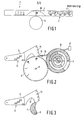
- the display device has an aperture 1 shown in FIG. 1 with four program display windows 2 and five program execution windows 3.
- the aperture can be designed as a perforated aperture with perforated windows or as a glass pane, preferably as a plexiglass pane, which is covered with a layer of paint except for the windows. These windows lie on a straight, horizontal line. Numbers are attached above the program display windows 2, which indicate which program has just been set when a mark appears in the window under the corresponding number.
- Symbols 4 are attached above the program flow windows 3 and are assigned to the individual program steps. If a mark appears behind a program sequence window 3, it is displayed that the program step corresponding to the symbol 4 above it has been carried out becomes.
- the rotary knob 5 sits together with a toothed disk 6 shown in FIG. 2 and a cam disk 7 arranged behind it and shown in FIG. 3 on an axis 8 of a program switching mechanism not shown in the figures.
- the axis 8 can be the axis of rotation of a program knob disk, which is part of a program switching mechanism known for example from DE-AS 19 07 725.
- the toothed disk 6 is in engagement with the toothing of a program execution disk 10 provided with circular markings, which is arranged behind the program execution windows 3 and which, driven by the toothed disk 6, rotates counterclockwise during the program execution.
- the program execution windows 3 are indicated in Fig. 2.
- the rocker arm 11 is shown in FIG. 2, which has a marker 12 for each selectable program, which is visible behind the corresponding program display window 2 after the program has been set.
- On the pivotable side of the rocker arm 11 there are cutouts 14 into which a wire 16 guided in a Bowden cable 15 engages can to lock the rocker arm 11. This locking is triggered by actuating a start button 17, by means of which the set program is started at the same time.
- the cam disk 7 shown in FIG. 3 is in contact with the rocker arm 11, which has a recess 13 into which the cam disk 7, which rotates clockwise when the program is running, can enter without the rotary lever 11 blocking its rotary movement prematurely.
- the rotary knob 5 is turned clockwise until the number of the program to be set appears behind the window 18.
- the cam disc 7 rotates clockwise, so that the rocking lever 11 in contact with it performs a pivoting movement in a clockwise direction.
- one of the markings 12 appears behind that program display window 2 which corresponds to the set program.
- the program sequence disc 10 is also rotated via the toothed disc 6, so that a mark that corresponds to the first program step of the selected program appears behind that program sequence window 3.
- the program 4 is set so that the number 4 is visible in the window 18 and a marking is visible behind the fourth program display window 2.
- the start button 17 is pressed.
- the wire end 16 is pushed into one of the recesses 14 and thus the rocker arm 11 is locked in the pivot position corresponding to the set program.
- the corresponding marker 12 thus remains behind the pro when this program runs gram display window 2 visible.
- the axis 8 rotates so that the cam disc 7 also rotates clockwise and its nose moves away from the rocker arm 11.
- the toothed disk 6 also rotates clockwise, so that the program execution disk 10 driven thereby rotates counterclockwise and 3 markings appear behind the program execution windows, which indicate which program step is currently being carried out.
Landscapes
- Engineering & Computer Science (AREA)
- Textile Engineering (AREA)
- Physics & Mathematics (AREA)
- General Physics & Mathematics (AREA)
- Automation & Control Theory (AREA)
- Control Of Washing Machine And Dryer (AREA)
- Input From Keyboards Or The Like (AREA)
- Detail Structures Of Washing Machines And Dryers (AREA)
- Displays For Variable Information Using Movable Means (AREA)
- Mechanical Control Devices (AREA)
Abstract
Description
Anzeigevorrichtung für ein programmgesteuertes Haushaltsgerät, insbesondere für eine Wasch- oder Geschirrspülmaschine bzw. einen WäschetrocknerDisplay device for a program-controlled household appliance, in particular for a washing machine or dishwasher or a tumble dryer
Die Erfindung bezieht sich auf eine Vorrichtung zur Anzeige des gewählten Programmes und des Programmablaufes eines programmgesteuerten Haushaltsgerätes, insbesondere einer Wasch- oder Geschirrspülmaschine bzw. eines Wäschetrockners mit einem auf der Achse eines Programmschaltwerkes sitzenden Drehknopf zur Programmwahl, der eine feststehende Anzeige des gewählten Programmes bewirkt, und mit einer vom Programmschaltwerk angetriebenen Programmablaufscheibe, die hinter einer Blende mit Programmablauffenstern umläuft, und mit Markierungen versehen ist, die während des Programmablaufes durch die Programmablauffenster hindurch den jeweils ablaufenden Programmschritt anzeigen.The invention relates to a device for displaying the selected program and the program sequence of a program-controlled household appliance, in particular a washing machine or dishwasher or a tumble dryer, with a rotary knob for program selection which is located on the axis of a program switching mechanism and which causes a fixed display of the selected program. and with a program sequence disk driven by the program switching mechanism, which rotates behind a panel with program sequence windows, and is provided with markings which indicate the program step in progress through the program sequence window during the program sequence.
Aus der DE-AS 19 07 725 ist eine Vorrichtung zur Anzeige des gewählten Programmes und des Programmablaufes einer programmgesteuerten Wasch- oder Geschirrspülmaschine mit einem Drehknopf bekannt, der auf einer Welle eines Programmschaltwerkes sitzt und mit dessen Hilfe eines der im Programmschaltwerk gespeicherten Programme einstellbar ist. Hierzu wird der Drehknopf soweit gedreht, bis eine am Drehknopf angebrachte Spitze auf die dem ausgewählten Programm entsprechende Markierung zeigt. Bei Ablauf des Programmes verbleibt der Drehknopf dann in dieser Position. Beim Einstellen des Programmes wird vom Drehknopf eine hinter einer Blende angeordnete Programmablaufscheibe mit einem Zeiger mitgenommen, der bei Ablauf des Programmes mitläuft und jeweils auf eine dem gerade ablaufenden Programmschritt entsprechende Markierung zeigt. Hierbei sind sowohl die Markierungen für die wählbaren Programme und die ablaufenden Programmschritte als auch die Spitze des Drehknopfes und der Zeiger so eng nebeneinander angeordnet, daß ohne zusätzliche Erläuterung nicht erkennbar ist, auf welche Markierungen der Zeiger und auf welche Markierungen die Spitze des Drehknopfes zeigen, so daß sich hierbei Ablesefehler ergeben können.From DE-AS 19 07 725 a device for displaying the selected program and the program sequence of a program-controlled washing machine or dishwasher with a rotary knob is known, which sits on a shaft of a program switching mechanism and with the help of which one of the programs stored in the program switching mechanism can be set. To do this, turn the rotary knob until a tip on the rotary knob points to the marking corresponding to the selected program. When the program runs, the rotary knob remains in this position. When setting the program, the rotary knob carries along a program sequence disc arranged behind a panel with a pointer which runs along with the program and points to a marking corresponding to the program step currently being carried out. Here, the markings for the selectable programs and the running program steps as well as the tip of the rotary knob and the pointer are so closely arranged net that it is not recognizable without additional explanation to which markings the pointer and which markings point the tip of the rotary knob, so that reading errors can result.
Aufgabe der Erfindung ist es, eine Vorrichtung zu schaffen, mit deren Hilfe das eingestellte Programm und der gerade ablaufende Programmschritt eines programmgesteuerten Haushaltsgerätes übersichtlich und gut ablesbar angezeigt werden.The object of the invention is to provide a device with the aid of which the set program and the currently running program step of a program-controlled household appliance are clearly and legibly displayed.
Diese Aufgabe wird bei einer Anzeigevorrichtung eingangs genannter Art dadurch gelöst, daß die Blende eine oder mehrere Programmanzeigefenster aufweist und über den Drehknopf ein Schwinghebel betätigbar ist, der für jedes wählbare Programm eine Markierung aufweist und in einer Schwenkposition arretierbar ist, bei der die einem Programm entsprechende Markierung hinter dem Programmanzeigefenster erscheint.This object is achieved in a display device of the type mentioned above in that the diaphragm has one or more program display windows and a rocker arm can be actuated via the rotary knob, which has a mark for each selectable program and can be locked in a pivoting position in which the program corresponds to a program Marking behind the program display window appears.
Die Übersichtlichkeit der Anzeigevorrichtung wird weiter verbessert, wenn die Programmanzeige- und die Programmablauffenster auf einer geraden, waagerechten Linie angeordnet sind.The clarity of the display device is further improved if the program display and the program execution windows are arranged on a straight, horizontal line.
In einer vorteilhaften Ausgestaltung der Erfindung steht das freie Ende des Schwinghebels mit der Kurvenfläche einer auf der Achse sitzenden Kurvenscheibe in Berührung. Hierbei ist der mit Markierungen versehene Schwinghebel mittels der Kurvenscheibe auf einfache Weise in diejenige Schwenkposition bringbar, bei der die dem gewählten Programm entsprechende Markierung hinter einem Programmanzeigefenster erscheint.In an advantageous embodiment of the invention, the free end of the rocking lever is in contact with the curved surface of a cam disk seated on the axis. Here, the rocker arm provided with markings can be easily brought into the pivoting position by means of the cam disc, in which the marking corresponding to the selected program appears behind a program display window.
Um den Schwinghebel durch Betätigung einer entfernt angeordneten Starttaste arretieren zu können, ist es vorteilhaft, wenn der Schwinghebel an seiner Vorderseite mit Aussparungen versehen ist, in die ein in einem Bowdenzug geführter Draht in jeder einem wählbaren Programm entsprechenden Schwenkposition arretierend eingreifbar ist.To the rocker arm by pressing one away To be able to lock the start button, it is advantageous if the rocker arm is provided on its front with recesses into which a wire guided in a Bowden cable can be locked in any pivot position corresponding to a selectable program.
Ein Ausführungsbeispiel der Erfindung wird im folgenden anhand der Zeichnungen beschrieben. Es zeigen
- Fig. 1 eine Blende mit auf einer Linie liegenden Programmanzeige- und Programmablauffenster,
- Fig. 2 einen Schwinghebel und eine Programmablaufscheibe, auf denen Markierungen angebracht sind,
- Fig. 3 eine mit dem Schwinghebel in Berührung stehende Kurvenscheibe.
- 1 is an aperture with program display and program sequence window lying on a line,
- 2 shows a rocker arm and a program execution disk, on which markings are attached,
- Fig. 3 is a cam disc in contact with the rocker arm.
Die Anzeigevorrichtung weist eine in Fig. 1 dargestellte Blende 1 mit vier Programmanzeigefenster 2 und fünf Programmablauffenster 3 auf. Die Blende kann als Lochblende mit lochförmigen Fenstern oder als Glasscheibe, vorzugsweise als Plexiglasscheibe ausgebildet sein, welche bis auf die Fenster mit einer Farbschicht bedeckt ist. Diese Fenster liegen auf einer geraden, waagerechten Linie. Über den Programmanzeigefenstern 2 sind Zahlen angebracht, die anzeigen, welches Programm gerade eingestellt wurde, wenn in dem Fenster unter der entsprechenden Zahl eine Markierung erscheint.The display device has an
über den Programmablauffenstern 3 sind Symbole 4 angebracht, die den einzelnen Programmschritten zugeordnet sind. Erscheint hinter einem Programmablauffenster 3 eine Markierung, wird angezeigt, daß der dem darüber angebrachten Symbol 4 entsprechende Programmschritt ausgeführt wird. Nahe den Programmablauf- und Programmanzeigefenstern 2 und 3 ist ein im Uhrzeigersinn drehbarer Drehknopf 5 zum Einstellen der Programme angeordnet. Der Drehknopf 5 sitzt gemeinsam mit einer in Fig. 2 dargestellten Zahnscheibe 6 und einer dahinter angeordneten und in Fig. 3 dargestellten Kurvenscheibe 7 auf einer Achse 8 eines in den Figuren nicht dargestellten Programmschaltwerkes. Hierbei kann die Achse 8 die Drehachse einer Programmnoppenscheibe sein, die Teil eines beispielsweise aus der DE-AS 19 07 725 bekannten Programmschaltwerkes ist.
Auf der in Fig. 2 dargestellten Zahnscheibe 6 sind Zahlen angebracht, die, wie Fig. 1 zeigt, hinter einem kreissegmentförmigen Fenster 18 der Blende 1 sichtbar sind und anzeigen, welches Programm gerade eingestellt ist. Bei Programmablauf dreht sich die Achse 8 und damit auch die Zahnscheibe 6 im Uhrzeigersinn, so daß die dem eingestellten Programm entsprechende Zahl hinter der Blende 1 verschwindet, während die dem eingestellten Programm entsprechende Markierung hinter dem Programmanzeigefenster 2 sichtbar bleibt.Numbers are attached to the
Die Zahnscheibe 6 steht mit der Verzahnung einer mit kreisförmigen Markierungen versehenen Programmablaufscheibe 10 in Eingriff, die hinter den Programmablauffenstern 3 angeordnet ist und die sich, angetrieben von der Zahnscheibe 6, bei Programmablauf gegen den Uhrzeigersinn dreht. Die Programmablauffenster 3 sind in Fig. 2 andeutungsweise eingezeichnet. Weiterhin ist in Fig. 2 der Schwinghebel 11 dargestellt, der für jedes wählbare Programm eine Markierung 12 aufweist, die nach Einstellung des Programms hinter dem entsprechenden Programmanzeigefenster 2 sichtbar ist. An der schwenkbaren Seite des Schwinghebels 11 sind Aussparungen 14 angebracht, in die ein in einem Bowdenzug 15 geführter Draht 16 eingreifen kann, um den Schwinghebel 11 zu arretieren. Diese Arretierung wird durch Betätigung eines Startknopfes 17 ausgelöst, durch den gleichzeitig das eingestellte Programm gestartet wird.The
Die in Fig. 3 dargestellte Kurvenscheibe 7 steht mit dem Schwinghebel 11 in Berührung, der eine Ausnehmung 13 aufweist, in welche die sich bei Programmablauf im Uhrzeigersinn drehende Kurvenscheibe 7 einlaufen kann, ohne daß deren Drehbewegung vom Schwinghebel 11 vorzeitig blockiert wird.The cam disk 7 shown in FIG. 3 is in contact with the
Zum Einstellen eines Programmes wird der Drehknopf 5 soweit im Uhrzeigersinn gedreht, bis hinter dem Fenster 18 die Zahl des einzustellenden Programmes erscheint. Hierbei dreht sich auch die Kurvenscheibe 7 im Uhrzeigersinn, so daß der damit in Berührung stehende Schwinghebel 11 eine Schwenkbewegung im Uhrzeigersinn ausführt. Dadurch erscheint eine der Markierungen 12 hinter demjenigen Programmanzeigefenster 2, das dem eingestellten Programm entspricht. Bei der Einstellung des Programmes wird über die Zahnscheibe 6 auch die Programmablaufscheibe 10 verdreht, so daß hinter demjenigen Programmablauffenster 3 eine Markierung erscheint, das dem ersten Programmschritt des gewählten Programmes entspricht. Im vorliegenden Ausführungsbeispiel ist das Programm 4 eingestellt, so daß im Fenster 18 die Zahl 4 und hinter dem vierten Programmanzeigefenster 2 eine Markierung sichtbar ist.To set a program, the
Zum Starten des eingestellten Programmes wird die Starttaste 17 gedrückt. Hierdurch wird das Drahtende 16 in eine der Aussparungen 14 geschoben und damit der Schwinghebel 11 in der dem eingestellten Programm entsprechenden Schwenkposition arretiert. Die entsprechende Markierung 12 bleibt bei Ablauf dieses Programmes somit hinter dem Programmanzeigefenster 2 sichtbar. Bei Programmablauf dreht sich die Achse 8, so daß sich auch die Kurvenscheibe 7 im Uhrzeigersinn dreht und sich dabei deren Nase vom Schwinghebel 11 entfernt.To start the set program, the
Außerdem dreht sich hierbei angetrieben von der Achse 8 auch die Zahnscheibe 6 im Uhrzeigersinn, so daß sich die hiervon angetriebene Programmablaufscheibe 10 gegen den Uhrzeigersinn dreht und hinter den Programmablauffenstern 3 Markierungen erscheinen, die angeben, welcher Programmschritt gerade abläuft.In addition, driven by the axis 8, the
Claims (4)
Applications Claiming Priority (2)
| Application Number | Priority Date | Filing Date | Title |
|---|---|---|---|
| DE3536776 | 1985-10-16 | ||
| DE19853536776 DE3536776A1 (en) | 1985-10-16 | 1985-10-16 | DISPLAY DEVICE FOR A PROGRAM-CONTROLLED HOUSEHOLD APPLIANCE, IN PARTICULAR FOR A WASHING OR DISHWASHER, OR A LAUNDRY DRYER |
Publications (3)
| Publication Number | Publication Date |
|---|---|
| EP0219172A2 true EP0219172A2 (en) | 1987-04-22 |
| EP0219172A3 EP0219172A3 (en) | 1988-02-03 |
| EP0219172B1 EP0219172B1 (en) | 1992-04-15 |
Family
ID=6283640
Family Applications (1)
| Application Number | Title | Priority Date | Filing Date |
|---|---|---|---|
| EP86201768A Expired - Lifetime EP0219172B1 (en) | 1985-10-16 | 1986-10-13 | Indicating device for a programme-controlled household appliance, particularly for a laundry or dishwashing machine or a laundry dryer |
Country Status (3)
| Country | Link |
|---|---|
| EP (1) | EP0219172B1 (en) |
| DE (2) | DE3536776A1 (en) |
| ES (1) | ES2031817T3 (en) |
Cited By (3)
| Publication number | Priority date | Publication date | Assignee | Title |
|---|---|---|---|---|
| FR2641908A1 (en) * | 1989-01-12 | 1990-07-20 | Esswein Sa | Control panel for domestic electrical appliance |
| FR2693897A1 (en) * | 1992-07-23 | 1994-01-28 | Zanussi Elettrodomestici | Built-in dishwasher with hidden control panel. |
| ES2078859A2 (en) * | 1992-09-21 | 1995-12-16 | Bosch Siemens Hausgeraete | Adjustable indicating equipment for a domestic appliance. |
Citations (2)
| Publication number | Priority date | Publication date | Assignee | Title |
|---|---|---|---|---|
| DE1907725A1 (en) * | 1969-02-15 | 1970-09-03 | Holzer Patent Ag | Device for preselecting a program and for displaying the program sequence of program switching mechanisms |
| FR2210319A5 (en) * | 1972-12-07 | 1974-07-05 | Sedelem |
-
1985
- 1985-10-16 DE DE19853536776 patent/DE3536776A1/en not_active Withdrawn
-
1986
- 1986-10-13 EP EP86201768A patent/EP0219172B1/en not_active Expired - Lifetime
- 1986-10-13 ES ES198686201768T patent/ES2031817T3/en not_active Expired - Lifetime
- 1986-10-13 DE DE8686201768T patent/DE3684864D1/en not_active Expired - Fee Related
Patent Citations (2)
| Publication number | Priority date | Publication date | Assignee | Title |
|---|---|---|---|---|
| DE1907725A1 (en) * | 1969-02-15 | 1970-09-03 | Holzer Patent Ag | Device for preselecting a program and for displaying the program sequence of program switching mechanisms |
| FR2210319A5 (en) * | 1972-12-07 | 1974-07-05 | Sedelem |
Cited By (3)
| Publication number | Priority date | Publication date | Assignee | Title |
|---|---|---|---|---|
| FR2641908A1 (en) * | 1989-01-12 | 1990-07-20 | Esswein Sa | Control panel for domestic electrical appliance |
| FR2693897A1 (en) * | 1992-07-23 | 1994-01-28 | Zanussi Elettrodomestici | Built-in dishwasher with hidden control panel. |
| ES2078859A2 (en) * | 1992-09-21 | 1995-12-16 | Bosch Siemens Hausgeraete | Adjustable indicating equipment for a domestic appliance. |
Also Published As
| Publication number | Publication date |
|---|---|
| DE3536776A1 (en) | 1987-04-16 |
| ES2031817T3 (en) | 1993-01-01 |
| DE3684864D1 (en) | 1992-05-21 |
| EP0219172B1 (en) | 1992-04-15 |
| EP0219172A3 (en) | 1988-02-03 |
Similar Documents
| Publication | Publication Date | Title |
|---|---|---|
| WO2003023118A1 (en) | Display in a household appliance | |
| DE19824100A1 (en) | Electronic device with a rotary switch and a display screen | |
| EP0219172B1 (en) | Indicating device for a programme-controlled household appliance, particularly for a laundry or dishwashing machine or a laundry dryer | |
| DE10144666B4 (en) | Control of a light ring | |
| DE2132064A1 (en) | SETUP ON A ZIG-ZAG OR AUTOMATIC SEWING MACHINE TO ADJUST STITCH POSITION AND STITCH WIDTH | |
| DE1907725A1 (en) | Device for preselecting a program and for displaying the program sequence of program switching mechanisms | |
| EP0204219A1 (en) | Blind stitch sewing machine | |
| DE3915158C2 (en) | Device for displaying the program sequence and / or the selected program in household appliances | |
| DE2624452C3 (en) | Device for setting mixing ratios of two liquid components, in particular for a fuel pump dispensing a fuel mixture | |
| DE423247C (en) | Device for moving the slide on calculating machines | |
| DE1660806C3 (en) | Decorative stitch selection device for zigzag sewing machines | |
| DE2748913C3 (en) | Extractor hood with a device for displaying the degree of saturation for its fat and / or odor filter | |
| DE1760098A1 (en) | Household appliance with several programs | |
| EP0863242A2 (en) | Program setting- and display arrangement for a program controlled washing machine | |
| DE3217707A1 (en) | Device for switch position indication in electrically operated domestic apparatuses | |
| DE2805856A1 (en) | PROGRAM SELECTOR WITH ROTARY CONTROL | |
| DE1897989U (en) | DISPLAY DEVICE FOR PROGRAM CONTROLLED DEVICES. | |
| DE2820028A1 (en) | DEVICE FOR SELECTING A CAM FOR SEWING MACHINES | |
| DE410689C (en) | Device on calculating machines for returning the cams to the zero position | |
| DE2711246C3 (en) | Adjustable timer | |
| DE2116910C2 (en) | Device for preventing the coinless operation of a self-collecting time control device | |
| DE1490347C3 (en) | Ripple control receiver with a switching arm driven by a synchronous motor | |
| DE513502C (en) | Flat sewing machine | |
| DE1763090A1 (en) | Cam disk control device, especially for washing machines | |
| DE3724300C1 (en) | Display device for electrically operated domestic appliances |
Legal Events
| Date | Code | Title | Description |
|---|---|---|---|
| PUAI | Public reference made under article 153(3) epc to a published international application that has entered the european phase |
Free format text: ORIGINAL CODE: 0009012 |
|
| AK | Designated contracting states |
Kind code of ref document: A2 Designated state(s): DE ES FR GB IT SE |
|
| PUAL | Search report despatched |
Free format text: ORIGINAL CODE: 0009013 |
|
| AK | Designated contracting states |
Kind code of ref document: A3 Designated state(s): DE ES FR GB IT SE |
|
| 17P | Request for examination filed |
Effective date: 19880708 |
|
| RAP1 | Party data changed (applicant data changed or rights of an application transferred) |
Owner name: N.V. PHILIPS' GLOEILAMPENFABRIEKEN Owner name: BAUKNECHT HAUSGERAETE GMBH |
|
| RAP1 | Party data changed (applicant data changed or rights of an application transferred) |
Owner name: WHIRLPOOL INTERNATIONAL B.V. Owner name: BAUKNECHT HAUSGERAETE GMBH |
|
| 17Q | First examination report despatched |
Effective date: 19901025 |
|
| GRAA | (expected) grant |
Free format text: ORIGINAL CODE: 0009210 |
|
| AK | Designated contracting states |
Kind code of ref document: B1 Designated state(s): DE ES FR GB IT SE |
|
| REF | Corresponds to: |
Ref document number: 3684864 Country of ref document: DE Date of ref document: 19920521 |
|
| ITF | It: translation for a ep patent filed | ||
| ET | Fr: translation filed | ||
| GBT | Gb: translation of ep patent filed (gb section 77(6)(a)/1977) | ||
| REG | Reference to a national code |
Ref country code: ES Ref legal event code: FG2A Ref document number: 2031817 Country of ref document: ES Kind code of ref document: T3 |
|
| PLBE | No opposition filed within time limit |
Free format text: ORIGINAL CODE: 0009261 |
|
| STAA | Information on the status of an ep patent application or granted ep patent |
Free format text: STATUS: NO OPPOSITION FILED WITHIN TIME LIMIT |
|
| 26N | No opposition filed | ||
| PGFP | Annual fee paid to national office [announced via postgrant information from national office to epo] |
Ref country code: ES Payment date: 19931004 Year of fee payment: 8 |
|
| PGFP | Annual fee paid to national office [announced via postgrant information from national office to epo] |
Ref country code: SE Payment date: 19931018 Year of fee payment: 8 |
|
| PGFP | Annual fee paid to national office [announced via postgrant information from national office to epo] |
Ref country code: GB Payment date: 19941005 Year of fee payment: 9 |
|
| PG25 | Lapsed in a contracting state [announced via postgrant information from national office to epo] |
Ref country code: SE Effective date: 19941014 Ref country code: ES Free format text: LAPSE BECAUSE OF EXPIRATION OF PROTECTION Effective date: 19941014 |
|
| PGFP | Annual fee paid to national office [announced via postgrant information from national office to epo] |
Ref country code: FR Payment date: 19941028 Year of fee payment: 9 |
|
| PGFP | Annual fee paid to national office [announced via postgrant information from national office to epo] |
Ref country code: DE Payment date: 19941219 Year of fee payment: 9 |
|
| EAL | Se: european patent in force in sweden |
Ref document number: 86201768.8 |
|
| EUG | Se: european patent has lapsed |
Ref document number: 86201768.8 |
|
| PG25 | Lapsed in a contracting state [announced via postgrant information from national office to epo] |
Ref country code: GB Effective date: 19951013 |
|
| GBPC | Gb: european patent ceased through non-payment of renewal fee |
Effective date: 19951013 |
|
| PG25 | Lapsed in a contracting state [announced via postgrant information from national office to epo] |
Ref country code: FR Effective date: 19960628 |
|
| PG25 | Lapsed in a contracting state [announced via postgrant information from national office to epo] |
Ref country code: DE Effective date: 19960702 |
|
| REG | Reference to a national code |
Ref country code: FR Ref legal event code: ST |
|
| REG | Reference to a national code |
Ref country code: ES Ref legal event code: FD2A Effective date: 19990601 |
|
| PG25 | Lapsed in a contracting state [announced via postgrant information from national office to epo] |
Ref country code: IT Free format text: LAPSE BECAUSE OF NON-PAYMENT OF DUE FEES;WARNING: LAPSES OF ITALIAN PATENTS WITH EFFECTIVE DATE BEFORE 2007 MAY HAVE OCCURRED AT ANY TIME BEFORE 2007. THE CORRECT EFFECTIVE DATE MAY BE DIFFERENT FROM THE ONE RECORDED. Effective date: 20051013 |